1
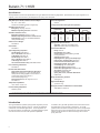
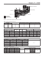
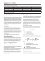
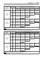
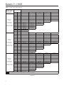
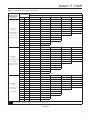
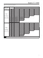
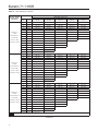
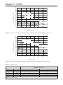
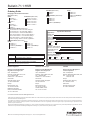
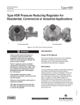
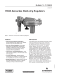
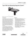
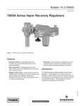
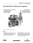
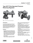
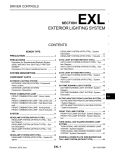
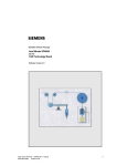
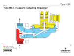
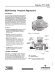
Bulletin 71.1:HSR
March 2013
Type HSR Pressure Reducing Regulator for
Residential, Commercial, or Industrial Applications
• High Capacity
• Compact Design
• High Capacity
Internal Relief
TYPE HSR ANGLE BODY
• Globe Bodies
• Angle Bodies
• Fixed Factor /
PFM Accuracy
TYPE HSR GLOBE BODY
D103087X012
• Meets or Exceeds
ANSI B109.4 / CGA 6.18 Requirements
www.fisherregulators.com
Bulletin 71.1:HSR
Specifications
The Specifications section lists specifications for Type HSR Pressure Reducing Regulators. Specifications for a given regulator as it
originally comes from the factory are stamped on the spring case nameplate.
Body Sizes (Inlet x Outlet) and End Connection Styles
3/4, 3/4 x 1, and 1 NPT
All sizes are available in Globe or Angle body.
Allowable Inlet Pressures(1)
Emergency: 150 psig / 10.3 bar
Maximum Operating Pressure: See Table 1
Allowable Outlet Pressures(1)
Emergency (Casing): 25 psig / 1.7 bar
Maximum Operating Pressure to Avoid Internal
Parts Damage: 3 psi / 0.21 bar differential above
outlet pressure setting
Outlet Pressure Ranges
See Table 2
Orifice Sizes
See Table 1
Typical Regulating Capacities
3/4 NPT Globe: See Table 8
3/4 x 1 NPT Globe: See Table 9
1 NPT Globe: See Table 10
3/4 NPT Angle: See Table 11
3/4 x 1 NPT Angle: See Table 12
1 NPT Angle: See Table 13
1% Pressure Factor Accuracy: See Tables 6 and 7
Flow and Sizing Coefficients
See Table 4
Internal Relief Performance
Approximate Internal Relief Start-To-Discharge
Point: 6 to 12-inches w.c. / 15 to 30 mbar above
outlet pressure setting (Applies to 6 to 8-inches w.c. /
15 to 20 mbar and 8 to 10-inches w.c. /
20 to 25 mbar springs only)
Relief Performance: See Figures 3 and 4,
and Table 14
Temperature Capabilities
-20 to 160°F / -29 to 71°C
Pressure Setting Adjustment
Adjusting Screw
Pressure Registration
Internal
Lockup Performance During Normal Operation
ORIFICE SIZE
LOCKUP ABOVE
SETPOINT
LOCKUP ABOVE
SETPOINT
Inches
mm
Inches w.c.
mbar
psi
mbar
1/8
3/16
1/4
3/8
1/2
3.2
4.8
6.4
9.5
13
1
1
2
2.5
3
2
2
5
6
7
0.15
0.15
0.15
0.15
0.15
10.3
10.3
10.3
10.3
10.3
Spring Case Vent Connection
Standard: 1 NPT with removable screen
Optional: 3/4 NPT with removable screen
Construction Materials
Body: Cast iron
Body Gasket: Nitrile (NBR)
Closing Cap: ASA thermoplastic (provides
UV-ray protection)
Adjusting Screw: Delrin®
Diaphragm Case, Spring Case, Diaphragm Plate, Orifice, and Valve Stem: Aluminum
Pusher Post or Relief Valve Seat: Delrin®
Diaphragm and Disk: Nitrile (NBR)
Control Spring: Zinc-plated steel
Relief Valve Spring: Stainless steel
Relief Valve Spring Retainer: Stainless steel
Vent Screen: Stainless steel
Lever Pin: Stainless steel
Spring Seat, Lever, and Other Metal Parts:
Plated steel
Body Vent Mounting Positions
See Figure 5
Approximate Weight
4 pounds / 2 kg
Designed, Tested, and Evaluated Consistent With:
ANSI B109.4 / CGA 6.18
1. The pressure/temperature limits in this Bulletin and any applicable standard or code limitation should not be exceeded.
Delrin® is a mark owned by E.I. du Pont de Nemours and Co.
Introduction
The Type HSR direct-operated, spring-loaded regulators provide
economical pressure reducing control in a variety of residential,
commercial, and industrial applications. These regulators can
be used with natural, manufactured, or liquefied petroleum gases
and have the same inlet and outlet pressure capabilities.
2
In addition, the Type HSR regulators have internal relief across
the diaphragm to help minimize overpressure. Any outlet
pressure above the start-to-discharge point of the nonadjustable
relief valve spring moves the diaphragm off the relief valve seat,
allowing excess pressure to bleed out through the screened
spring case vent.
Bulletin 71.1:HSR
CONTROL (MAIN) SPRING
STEM
RELIEF VALVE SPRING
VALVE DISK
PUSHER POST
ORIFICE
E0908
LEVER
INLET PRESSURE
OUTLET PRESSURE
ATMOSPHERIC PRESSURE
Figure 2. Type HSR Pressure Regulator Operational Schematic
Table 1. Maximum Operating Inlet Pressure
ORIFICE SIZE
Inch
mm
WIDE-OPEN Cg
FOR RELIEF SIZING
1/8
3/16
1/4
3/8
1/2
3.2
4.8
6.4
9.5
13
12.5
28.2
50.0
105
185
MAXIMUM OPERATING INLET PRESSURE TO OBTAIN GOOD REGULATING PERFORMANCE
psig
bar
125
100
60
30
20
8.6
6.9
4.1
2.1
1.2
Table 2. Outlet Pressure Ranges
OUTLET PRESSURE RANGE
SPRING
COLOR
STANDARD
CLOSING
CAP COLOR
Inches w.c.
mbar
SPRING PART
NUMBER
4 to 6
10 to 15
T14398T0012
Orange
SPRING WIRE DIAMETER
SPRING FREE LENGTH
Inch
mm
Inch
mm
Black
0.062
1.57
3.40
86.4
6 to 8
15 to 20
T14399T0012
Yellow
Black
0.067
1.70
3.61
91.4
8 to 10
20 to 25
T14405T0012
Black
Black
0.067
1.70
3.71
94.0
10 to 12.5
25 to 31
T14400T0012
Silver
Black
0.072
1.83
4.10
104
12.5 to 20
31 to 50
T14401T0012
Gray
Black
0.080
2.03
3.60
91.4
20 to 35
50 to 87
T14402T0012
Pink
Black
0.093
2.36
3.52
88.9
1.25 to 2.2 psig
0.09 to 0.15 bar
T14403T0012
Light Blue
Red
0.105
2.67
3.66
94.0
Table 3. Standard Outlet Pressures and Set Flows
OUTLET PRESSURE RANGE
STANDARD OUTLET SET PRESSURE
Inches w.c.
mbar
Inches w.c.
mbar
4 to 6
10 to 15
5
12
6 to 8
15 to 20
7
17
8 to 10
20 to 25
9
22
10 to 12.5
25 to 31
11
27
12.5 to 20
31 to 50
14
35
20 to 35
50 to 87
1 psi
0.07 bar
1.25 to 2.2 psig
0.09 to 0.15 bar
2 psi
0.14 bar
STANDARD SET GAS FLOW, SCFH / Nm3/h
50 / 1.3
Table 4. Flow and Sizing Coefficients
ORIFICE SIZE
Inch
mm
1/8
3.2
3/16
4.8
1/4
6.4
3/8
9.5
1/2
13
WIDE-OPEN RESIZING RELIEF SIZING
Cg
Cv
12.5
0.36
28.2
0.81
50
1.43
105
3.00
185
5.29
C1
35
XT
0.78
IEC SIZING COEFFICIENTS
FD
0.82
0.82
0.82
0.79
0.79
FL
0.89
3
Bulletin 71.1:HSR
Table 5. Standard Inlet Pressures for Set Flows
Inches
1/8
3/16
1/4
3/8
1/2
ORIFICE SIZE
INLET PRESSURE FOR SET FLOWS
psi
bar
60
4.1
50
3.5
30
2.1
15
1.0
10
0.69
mm
3.2
4.8
6.4
9.5
13
For each orifice size, the outlet pressure setting is made with the same inlet pressure regardless of outlet pressure. Example: 3/16-inch / 4.8 mm orifice uses 50 psi / 3.5 bar inlet for 5-inches w.c.
through 2 psi / 12 mbar through 0.14 bar outlet settings.
Principle of Operation
Capacity Information
Refer to Figure 2. When downstream demand decreases, the pressure
under the diaphragm increases. This pressure overcomes the regulator
setting (which is set by a spring). Through the action of the pusher post
assembly, lever, and stem the valve disk moves closer to the orifice and
reduces gas flow. If demand downstream increases, pressure under the
diaphragm decreases. Spring force pushes the pusher post assembly
downward and the valve disk moves away from the orifice. Type HSR
regulators include an internal relief valve for overpressure protection. If
the downstream pressure exceeds the regulator setting by 7-inches w.c.
to 1.25 psig / 17 mbar to 0.09 bar, depending on the main spring used,
the relief valve opens and excess gas escapes through the vent in the
upper spring case.
The high efficiency flow-through design provides maximum capacity
for a given orifice size. Tables 8 through 1 give the HSR Series flow
capacities at selected inlet pressures and outlet pressure settings.
Flows are in SCFH (at 60°F and 14.7 psia) and Nm3/h (at 0°C
and 1.01325 bar) of 0.6 specific gravity natural gas. To determine
equivalent capacities for air, propane, butane, or nitrogen,
multiply the listed SCFH capacity by the following appropriate
conversion factor: air–0.775 for air, propane–0.628, butane–0.548,
nitrogen–0.789. For gases of other specific gravities, multiply the
given SCFH capacity by 0.775 and divide by the square root of the
appropriate specific gravity. If capacity is desired in Nm3/h, multiply
SCFH by 0.0268.
Installation
The HSR Series regulators may be installed in any position.
However, the spring case vent should be pointed downward. If
gas escaping through the Type HSR internal relief valve could
constitute a hazard, the spring case vent must be piped to a
location where escaping gas will not be hazardous. If the vented
gas will be piped to another location, obstruction-free tubing or
piping at least equal to the vent, and the end of the vent pipe must
be protected from anything that might clog it. Dimensions are
shown in Figure 6.
Type HSR Flow Capacity for Pressure
Factor Measurement
Tables 6 and 7 contain the flow capacities for the Type HSR at
accuracies of +/- 1% of absolute pressure. This data can be used
in applying the regulator in Pressure Factor Measurement (also
called Fixed Factor Measurement) or other applications requiring
better accuracy. Normally pilot operated regulators with high
accuracy are required for these applications. However, as shown
in the table, by flow testing and by limiting the droop on flow
capacity, +/- 1% of absolute pressure is obtained.
Overpressure Protection
The wide-open Cg for relief sizing (see Table 1) along with the
capacity information should be used in choosing appropriate
overpressure protection devices to ensure that none of the limits in
the Specifications section are exceeded.
Overpressuring any portion of a regulator or associated equipment
may cause leakage, parts damage, or personal injury due to
bursting of pressure-containing parts or explosion of accumulated
gas. Regulator operation within ratings does not prevent the
possibility of damage from external sources or from debris in the
pipeline. A regulator should be inspected for damage after any
overpressure condition.
4
For Critical Pressure Drops
Use this equation for critical pressure drops (absolute outlet pressure
equal to one-half or less than one-half the absolute inlet pressure).
Q = P1(abs)Cg(1.29)
where,
Q
Cg
P1
= gas flow rate, SCFH
= gas sizing coefficient
= absolute inlet pressure, psia
For Non-Critical Pressure Drops
For pressure drops lower than critical (absolute outlet pressure greater
than one-half of absolute inlet pressure), use the following formula:
Q =
520
GT
CgP1SIN
3417
C1
P
P1
DEG
where,
Q
G
T
Cg
P1
C1
P
= gas flow rate, SCFH
= specific gravity of the gas
= absolute temperature of gas at inlet, °Rankine
= gas sizing coefficient
= absolute inlet pressure, psia
= flow coefficient
= pressure drop across the regulator, psi
Then, if capacity is desired in normal cubic meters per hour at 0°C
and 1.01325 bar, multiply SCFH by 0.0268.
Ordering Information
Carefully review each specification and complete the Ordering Guide
on page 20. Send the Ordering Guide to your local Sales Office.
Bulletin 71.1:HSR
Table 6. Typical HSR Regulating Capacities for a 3/4 NPT Outlet Body Size with 1% Pressure Factor Accuracy
OUTLET PRESSURE
SETTING
SPRING RANGE
DROOP/BOOST
1 psig /
0.07 bar
Spring T14402T0012
Color: Pink
+/- 1% ABS
2 psig /
0.14 bar
Spring T14403T0012
Color: Light Blue
+/- 1% ABS
INLET PRESSURE
psig
bar
2
3
5
10
0.14
0.21
0.34
0.69
15
20
30
40
1.0
1.4
2.1
2.8
50
60
80
100
125
3.5
4.1
5.5
6.9
8.6
3
5
10
15
0.21
0.34
0.69
1.0
20
30
40
50
1.4
2.1
2.8
3.5
60
80
100
125
4.1
5.5
6.9
8.6
CAPACITIES IN SCFH / Nm3/h OF 0.6 SPECIFIC GRAVITY GAS
Orifice Size, Inches / mm
1/8 / 3.2(1)
200 / 5.4
330 / 8.8
410 / 11.0
510 / 13.7
660 / 17.7
830 / 22.2
970 / 26.0
1130 / 30.3
1440 / 38.6
1760 / 47.2
2150 / 57.6
250 / 6.7
380 / 10.2
480 / 12.9
650 / 17.4
800 / 21.4
920 / 24.7
1100 / 29.5
1450 / 39.5
1750 / 46.9
2000 / 53.6
3/16 / 4.8(1)
220 / 5.9
380 / 10.2
600 / 16.1
810 / 21.7
1050 / 28.1
1500 / 40.2
1850 / 49.6
2120 / 56.8
2400 / 64.3
2600 / 69.7
2700 / 72.4
250 / 6.7
450 / 12.1
620 / 16.6
780 / 20.9
1150 / 30.8
1500 / 40.2
2020 / 54.1
2250 / 60.3
2500 / 67.0
2750 / 73.7
1/4 / 6.4(1)
3/8 / 9.5(2)
1/2 / 13(2)
220 / 5.9
350 / 9.4
520 / 13.9
890 / 23.9
1250 / 33.5
1520 / 40.7
2020 / 54.1
2320 / 62.2
2580 / 69.1
2850 / 76.4
390 / 10.5
570 / 15.3
830 / 22.2
1400 / 37.5
1750 / 46.9
2050 / 54.9
2400 / 64.3
570 / 15.3
770 / 20.6
1040 / 27.9
1710 / 45.8
2150 / 57.6
2380 / 63.8
200 / 5.4
350 / 9.4
650 / 17.4
950 / 25.5
1210 / 32.4
1680 / 45.0
1950 / 52.3
2300 / 61.6
2550 / 68.3
300 / 8.0
510 / 13.7
1020 / 27.3
1350 / 36.2
1680 / 45.0
2220 / 59.5
400 / 10.7
750 / 20.1
1340 / 35.9
1820 / 48.8
2120 / 56.8
1. Setpoint was established with an inlet of 10 psig / 0.69 bar. The regulators were not reset as inlet pressure was increased or decreased.
2. Setpoint was established with an inlet of 5 psig / 0.34 bar. The regulators were not reset as inlet pressure was increased or decreased.
Gray areas show where indicated droop/boost would be exceeded regardless of capacity.
Blank areas indicate where maximum operating inlet pressure is exceeded for a given orifice.
Table 7. Typical HSR Regulating Capacities for a 1 NPT Outlet Body Size with 1% Pressure Factor Accuracy
OUTLET PRESSURE
SETTING
SPRING RANGE
DROOP/BOOST
1 psig /
0.07 bar
Spring T14402T0012
Color: Pink
+/- 1% ABS
2 psig /
0.14 bar
Spring T14403T0012
Color: Light Blue
+/- 1% ABS
CAPACITIES IN SCFH / Nm3/h OF 0.6 SPECIFIC GRAVITY GAS
INLET PRESSURE
psig
bar
2
3
5
10
0.14
0.21
0.34
0.69
15
20
30
40
1.0
1.4
2.1
2.8
50
60
80
100
125
3.5
4.1
5.5
6.9
8.6
3
5
10
15
0.21
0.34
0.69
1.0
20
30
40
50
1.4
2.1
2.8
3.5
60
80
100
125
4.1
5.5
6.9
8.6
Orifice Size, Inches / mm
1/8 / 3.2(1)
200 / 5.4
330 / 8.8
410 / 11.0
510 / 13.7
660 / 17.7
830 / 22.2
970 / 26.0
1130 / 30.3
1440 / 38.6
1760 / 47.2
2150 / 57.6
250 / 6.7
380 / 10.2
480 / 12.9
650 / 17.4
800 / 21.4
920 / 24.7
1100 / 29.5
1450 / 38.9
1750 / 46.9
2000 / 53.6
3/16 / 4.8(1)
220 / 5.9
380 / 10.2
600 / 16.1
810 / 21.7
1050 / 28.1
1500 / 40.2
1850 / 49.6
2120 / 56.8
2500 / 67.0
3250 / 87.1
3950 / 106
250 / 6.7
450 / 12.1
620 / 16.6
780 / 20.9
1150 / 30.8
1500 / 40.2
2020 / 54.1
2250 / 60.3
2800 / 75.0
3500 / 93.8
1/4 / 6.4(1)
3/8 / 9.5(2)
1/2 / 13(2)
220 / 5.9
350 / 9.4
520 / 13.9
890 / 23.9
1250 / 33.5
1520 / 40.7
2020 / 54.1
2500 / 67.0
2900 / 77.7
3400 / 91.1
390 / 10.5
570 / 15.3
830 / 22.2
1400 / 37.5
2050 / 54.9
2600 / 69.7
3450 / 92.5
570 / 15.3
770 / 20.6
1150 / 30.8
1980 / 53.1
2550 / 68.3
3000 / 80.4
200 / 5.4
350 / 9.4
650 / 17.4
950 / 25.5
1210 / 32.4
1780 / 47.7
2080 / 55.7
2550 / 68.3
3000 / 80.4
300 / 8.0
510 / 13.7
1020 / 27.3
1510 / 40.5
1900 / 50.9
2800 / 75.0
400 / 10.7
750 / 20.1
1450 / 38.9
198 / 53.1
2350 / 63.0
1. Setpoint was established with an inlet of 10 psig / 0.69 bar. The regulators were not reset as inlet pressure was increased or decreased.
2. Setpoint was established with an inlet of 5 psig / 0.34 bar. The regulators were not reset as inlet pressure was increased or decreased.
Gray areas show where indicated droop/boost would be exceeded regardless of capacity.
Blank areas indicate where maximum operating inlet pressure is exceeded for a given orifice.
5
Bulletin 71.1:HSR
Table 8. 3/4 NPT Globe Body Capacities
OUTLET PRESSURE
SETTING, SPRING
RANGE, DROOP,
AND BOOST
CAPACITIES IN SCFH / Nm³/h OF 0.6 SPECIFIC GRAVITY NATURAL GAS
INLET PRESSURE
Orifice Size, Inches / mm
psig
bar
3/16 / 4.8
1/4 / 6.4
3/8 / 9.5
0.5
0.03
1
0.07
----
----
190 / 5.1
240 / 6.4
285 / 7.6
95 / 92.5
220 / 5.9
250 / 6.7
330 / 8.8
400 / 10.7
2
0.14
150 / 4.0
250 / 6.7
335 / 9.0
490 / 13.1
650 / 17.4
3
0.21
5
0.34
185 / 5.0
290 / 7.8
430 / 11.5
600 / 16.1
750 / 20.1
235 / 6.3
400 / 10.7
580 / 15.5
900 / 24.1
1100 / 29.5
10
4 to 6-inches w.c. /
10 to 15 mbar
15
0.69
325 / 8.7
775 / 20.8
1050 / 28.1
1200 / 32.2
1.0
420 / 11.3
980 / 26.3
1295 / 34.7
1-inch w.c. droop
2-inches w.c. boost
20
1.4
500 / 13.4
1120 / 30.0
1380 / 37.0
30
2.1
655 / 17.6
1475 / 39.5
40
2.8
820 / 22.0
1785 / 47.8
50
3.5
945 / 25.3
2150 / 57.6
60
4.1
1100 / 29.5
80
5.5
1400 / 37.5
100
6.9
1700 / 45.6
0.5
0.03
70 / 1.9
120 / 3.2
170 / 4.6
1
0.07
100 / 2.7
180 / 4.8
2
0.14
130 / 3.5
250 / 6.7
3
0.21
170 / 4.6
7-inches w.c. /
17 mbar
5
0.34
10
6 to 8-inches w.c. /
15 to 20 mbar
5-inches w.c. /
12 mbar
1/8 / 3.2
240 / 6.4
300 / 8.0
240 / 6.4
340 / 9.1
430 / 11.5
330 / 8.8
510 / 13.7
630 / 16.9
340 / 9.1
420 / 11.3
680 / 18.2
770 / 20.6
220 / 5.9
420 / 11.3
650 / 17.4
900 / 24.1
960 / 25.7
0.69
330 / 8.8
730 / 19.6
1100 / 29.5
1310 / 35.1
1310 / 35.1
15
1.0
430 / 11.5
1000 / 26.8
1380 / 37.0
1520 / 40.7
1520 / 40.7
20
1.4
530 / 14.2
1200 / 32.2
1560 / 41.8
1620 / 43.4
1620 / 43.4
30
2.1
680 / 18.2
1550 / 41.5
1840 / 49.3
1750 / 46.9
40
2.8
850 / 22.8
1900 / 50.9
1950 / 52.3
50
3.5
970 / 26.0
2200 / 59.0
2000 / 53.6
60
4.1
1150 / 30.8
2280 / 61.1
2100 / 56.3
80
5.5
1450 / 38.9
2350 / 63.0
100
6.9
1750 / 46.9
1900 / 50.9
125
8.6
2100 / 56.3
1
0.07
----
140 / 3.7
170 / 4.6
240 / 6.4
325 / 8.7
2
0.14
125 / 3.4
190 / 5.1
225 / 6.0
345 / 9.3
475 / 12.7
3
0.21
190 / 5.1
220 / 5.9
270 / 7.2
475 / 12.7
660 / 17.7
5
0.34
210 / 5.6
275 / 7.4
400 / 10.7
685 / 18.4
880 / 23.6
9-inches w.c. /
22 mbar
10
0.69
280 / 7.5
440 / 11.8
710 / 19.0
1235 / 33.1
1215 / 32.6
15
1.0
370 / 9.9
685 / 18.4
1235 / 33.1
1400 / 37.5
1400 / 37.5
8 to 10-inches w.c. /
20 to 25 mbar
20
1.4
485 / 13.0
945 / 25.3
1475 / 39.5
1540 / 41.3
1500 / 40.2
30
2.1
680 / 18.2
1475 / 39.5
1800 / 48.2
1690 / 45.3
1-inch w.c. droop
2-inches w.c. boost
40
2.8
835 / 22.4
1770 / 47.4
1925 / 51.6
50
3.5
990 / 26.5
2000 / 53.6
1960 / 52.5
60
4.1
1135 / 30.4
2155 / 57.7
2050 / 54.9
1-inch w.c. droop
2-inches w.c. boost
80
5.5
1440 / 38.6
2265 / 60.7
100
6.9
1750 / 46.9
2100 / 56.3
125
8.6
2120 / 56.8
Gray areas indicate capacities limited by either droop or boost.
Blank areas indicate where maximum operating inlet pressure is exceeded for a given orifice.
- continued -
6
1/2 / 13
Bulletin 71.1:HSR
Table 8. 3/4 NPT Globe Body Capacities (continued)
OUTLET PRESSURE
SETTING, SPRING
RANGE, DROOP,
AND BOOST
CAPACITIES IN SCFH / Nm³/h OF 0.6 SPECIFIC GRAVITY NATURAL GAS
INLET PRESSURE
Orifice Size, Inches / mm
psig
bar
1/8 / 3.2
3/16 / 4.8
1/4 / 6.4
3/8 / 9.5
1/2 / 13
1
0.07
80 / 2.1
150 / 4.0
200 / 5.4
240 / 6.4
330 / 8.8
2
0.14
120 / 3.2
200 / 5.4
270 / 7.2
420 / 11.3
530 / 14.2
3
0.21
150 / 4.0
250 / 6.7
350 / 9.4
530 / 14.2
680 / 18.2
5
0.34
190 / 5.1
340 / 9.1
480 / 12.9
770 / 20.6
860 / 23.1
11-inches w.c. /
27 mbar
10
0.69
290 / 7.8
550 / 14.7
910 / 24.4
1210 / 32.4
1210 / 32.4
15
1.0
400 / 10.7
840 / 22.5
1210 / 32.4
1380 / 37.0
1380 / 37.0
10 to 12.5-inches w.c. /
25 to 31 mbar
20
1.4
480 / 12.9
1140 / 30.6
1550 / 41.5
1590 / 42.6
1590 / 42.6
30
2.1
670 / 18.0
1530 / 41.0
1830 / 49.0
1810 / 48.5
1-inch w.c. droop
2-inches w.c. boost
40
2.8
820 / 22.0
1970 / 52.8
1950 / 52.3
50
3.5
970 / 26.0
2150 / 57.6
1990 / 53.3
60
4.1
1120 / 30.0
2260 / 60.6
2050 / 54.9
80
5.5
1420 / 38.0
2390 / 64.1
100
6.9
1730 / 46.4
1950 / 52.3
125
8.6
2110 / 56.6
1
0.07
80 / 2.1
140 / 3.8
190 / 5.1
290 / 7.8
330 / 8.8
2
0.14
120 / 3.2
230 / 6.2
300 / 8.0
430 / 11.5
570 / 15.3
3
0.21
160 / 4.3
290 / 7.8
360 / 9.6
580 / 15.5
730 / 19.6
5
0.34
210 / 5.6
360 / 9.6
500 / 13.4
760 / 20.4
970 / 26.0
14-inches w.c. /
35 mbar
10
0.69
320 / 8.6
570 / 15.3
890 / 23.9
1190 / 31.9
1290 / 34.6
15
1.0
410 / 11.0
820 / 22.0
1210 / 32.4
1460 / 39.1
1560 / 41.8
12.5 to 20-inches w.c. /
31 to 50 mbar
20
1.4
500 / 13.4
1050 / 28.1
1440 / 38.6
1660 / 44.5
1700 / 45.6
30
2.1
670 / 18.0
1500 / 40.2
1790 / 48.0
1850 / 49.6
2-inches w.c. droop
2-inches w.c. boost
40
2.8
830 / 22.2
1830 / 49.0
2020 / 54.1
50
3.5
970 / 26.0
2100 / 56.3
2100 / 56.3
60
4.1
1140 / 30.6
2120 / 56.8
2180 / 58.4
80
5.5
1440 / 38.6
2220 / 59.5
100
6.9
1770 / 47.4
2250 / 60.3
125
8.6
2140 / 57.4
2
0.14
120 / 3.2
250 / 6.7
310 / 8.3
420 / 11.3
3
0.21
150 / 4.0
280 / 7.5
380 / 10.2
570 / 15.3
770 / 20.6
5
0.34
220 / 5.9
380 / 10.2
550 / 14.7
830 / 22.2
1040 / 27.9
10
0.69
330 / 8.8
600 / 16.1
890 / 23.9
1310 / 35.1
1570 / 42.1
28-inches w.c. /
70 mbar
15
1.0
410 / 11.0
810 / 21.7
1220 / 32.7
1600 / 42.9
1860 / 49.9
20
1.4
510 / 13.7
1020 / 27.3
1490 / 39.9
1790 / 48.0
2020 / 54.1
20 to 35-inches w.c. /
50 to 87 mbar
30
2.1
660 / 17.7
1440 / 38.6
1820 / 48.8
2100 / 56.3
40
2.8
830 / 22.2
1800 / 48.2
2080 / 55.7
± 1% ABS
50
3.5
970 / 26.0
1980 / 53.1
2280 / 61.1
60
4.1
1130 / 30.3
2320 / 62.2
2380 / 63.8
80
5.5
1440 / 38.6
2400 / 64.3
100
6.9
1760 / 47.2
2500 / 67.0
125
8.6
2150 / 57.6
570 / 15.3
Gray areas indicate capacities limited by either droop or boost.
Blank areas indicate where maximum operating inlet pressure is exceeded for a given orifice.
- continued -
7
Bulletin 71.1:HSR
Table 8. 3/4 NPT Globe Body Capacities (continued)
OUTLET PRESSURE
SETTING, SPRING
RANGE, DROOP,
AND BOOST
CAPACITIES IN SCFH / Nm³/h OF 0.6 SPECIFIC GRAVITY NATURAL GAS
INLET PRESSURE
Orifice Size, Inches / mm
psig
bar
1/8 / 3.2
3/16 / 4.8
1/4 / 6.4
3/8 / 9.5
2
0.14
3
0.21
5
0.34
150 / 4.0
310 / 8.3
470 / 12.6
710 / 19.0
930 / 24.9
180 / 4.8
390 / 10.5
590 / 15.8
940 / 25.2
1230 / 33.0
250 / 6.7
530 / 14.2
840 / 22.5
1290 / 34.6
1600 / 42.9
10
0.69
360 / 9.6
810 / 21.7
1320 / 35.4
1890 / 50.7
2200 / 59.0
28-inches w.c. /
70 mbar
15
1.0
430 / 11.5
1010 / 27.1
1650 / 44.2
2290 / 61.4
2530 / 67.8
20
1.4
530 / 14.2
1200 / 32.2
1940 / 52.0
2490 / 66.7
2750 / 73.7
20 to 35-inches w.c. /
50 to 87 mbar
30
2.1
670 / 18.0
1570 / 42.1
2430 / 65.1
2900 / 77.7
40
2.8
830 / 22.2
1920 / 51.5
2720 / 72.9
50
3.5
970 / 26.0
2280 / 61.1
2830 / 75.8
60
4.1
1130 / 30.3
2630 / 70.5
3050 / 81.7
80
5.5
1440 / 38.6
3050 / 81.7
100
6.9
1760 / 47.2
3150 / 84.4
125
8.6
2150 / 57.6
3
0.21
120 / 3.2
± 2% ABS
2 psig /
0.14 bar
1.25 to 2.2 psig /
0.09 to 0.15 bar
± 1% ABS
2 psig /
0.14 bar
1.25 to 2.2 psig /
0.09 to 0.15 bar
± 2 % ABS
190 / 5.1
250 / 6.7
330 / 8.8
450 / 12.1
5
0.34
150 / 4.0
270 / 7.2
360 / 9.6
560 / 15.0
750 / 20.1
10
0.69
250 / 6.7
430 / 11.5
620 / 16.6
1020 / 27.3
1340 / 35.9
15
1.0
330 / 8.8
600 / 16.1
800 / 21.4
1350 / 36.2
1480 / 39.7
20
1.4
410 / 11.0
740 / 19.8
1040 / 27.9
1540 / 41.3
1800 / 48.2
1850 / 49.6
30
2.1
560 / 15.0
1050 / 28.1
1450 / 38.9
40
2.8
730 / 19.6
1320 / 35.4
1640 / 44.0
50
3.5
870 / 23.3
1620 / 43.4
1900 / 50.9
60
4.1
1030 / 27.6
1910 / 51.2
2140 / 57.4
80
5.5
1350 / 36.2
2090 / 56.0
100
6.9
1650 / 44.2
2180 / 58.4
125
8.6
2000 / 53.6
3
0.21
150 / 4.0
270 / 7.2
420 / 11.3
600 / 16.1
790 / 21.2
5
0.34
210 / 5.6
420 / 11.3
620 / 16.6
960 / 25.7
1230 / 33.0
10
0.69
340 / 9.1
700 / 18.8
1050 / 28.1
1430 / 38.3
1880 / 50.4
15
1.0
440 / 11.8
940 / 25.2
1350 / 36.2
1880 / 50.4
2230 / 59.8
20
1.4
520 / 13.9
1150 / 30.8
1620 / 43.4
2260 / 60.6
2540 / 68.1
30
2..1
670 / 18.0
1540 / 41.3
2110 / 56.6
2520 / 67.5
40
2.8
830 / 22.2
1880 / 50.4
2430 / 65.1
50
3.5
970 / 26.0
2170 / 58.2
2640 / 70.8
60
4.1
1130 / 30.3
2460 / 65.9
2850 / 76.4
80
5.5
1450 / 38.9
2850 / 76.4
100
6.9
1750 / 46.9
3000 / 80.4
125
8.6
2100 / 56.3
Blank areas indicate where maximum operating inlet pressure is exceeded for a given orifice.
8
1/2 / 13
Bulletin 71.1:HSR
Table 9. 3/4 x 1 NPT Globe Body Capacities
OUTLET PRESSURE
SETTING, SPRING
RANGE, DROOP,
AND BOOST
5-inches w.c. /
12 mbar
CAPACITIES IN SCFH / Nm³/h OF 0.6 SPECIFIC GRAVITY NATURAL GAS
INLET PRESSURE
Orifice Size, Inches / mm
psig
bar
1/8 / 3.2
3/16 / 4.8
1/4 / 6.4
3/8 / 9.5
1/2 / 13
0.5
0.03
----
----
190 / 5.1
240 / 6.4
285 / 7.6
1
0.07
110 / 3.0
220 / 5.9
250 / 6.7
355 / 9.5
450 / 12.1
2
0.14
170 / 4.6
250 / 6.7
340 / 9.1
490 / 13.1
770 / 20.6
3
0.21
210 / 5.6
340 / 9.1
500 / 13.4
750 / 20.1
1000 / 26.8
5
0.34
245 / 6.6
400 / 10.7
750 / 20.1
1190 / 31.9
1330 / 35.6
1585 / 42.5
10
0.69
375 / 10.1
785 / 21.0
1290 / 34.6
4 to 6-inches w.c. /
10 to 15 mbar
15
1.0
475 / 12.7
995 / 26.7
1590 / 42.6
20
1.4
565 / 15.1
1160 / 31.1
1850 / 49.6
1-inch w.c. droop
2-inches w.c. boost
30
2.1
740 / 19.8
1475 / 39.5
40
2.8
900 / 24.1
1840 / 49.3
50
3.5
1050 / 28.1
2180 / 58.4
60
4.1
1215 / 32.6
80
5.5
1555 / 41.7
100
6.9
1880 / 50.4
1
0.07
----
150 / 4.0
170 / 4.6
240 / 6.4
325 / 8.7
2
0.14
125 / 3.4
190 / 5.1
225 / 6.0
345 / 9.3
475 / 12.7
3
0.21
195 / 5.2
220 / 5.9
270 / 7.2
475 / 12.7
660 / 17.7
5
0.34
210 / 5.6
275 / 7.4
400 / 10.7
685 / 18.4
880 / 23.6
9-inches w.c. /
22 mbar
10
0.69
280 / 7.5
440 / 11.8
710 / 19.0
1235 / 33.1
1250 / 33.5
15
1.0
370 / 9.9
685 / 18.4
1360 / 36.4
1585 / 42.5
1400 / 37.5
8 to 10-inches w.c. /
20 to 25 mbar
20
1.4
485 / 13.0
945 / 25.3
1610 / 43.1
1820 / 48.8
1540 / 41.3
30
2.1
680 / 18.2
1485 / 39.8
2080 / 55.7
2110 / 56.6
1-inch w.c. droop
2-inches w.c. boost
40
2.8
885 / 23.7
1840 / 49.3
2300 / 61.6
50
3.5
1050 / 28.1
2150 / 57.6
2760 / 74.0
60
4.1
1215 / 32.6
2475 / 66.3
3115 / 83.5
80
5.5
1530 / 41.0
3150 / 84.4
100
6.9
1855 / 49.7
2900 / 77.7
125
8.6
2300 / 61.6
Gray areas indicate capacities limited by either droop or boost.
Blank areas indicatewhere maximum operating inlet pressure is exceeded for a given orifice.
9
Bulletin 71.1:HSR
Table 10. 1 NPT Globe Body Capacities
OUTLET PRESSURE
SETTING, SPRING
RANGE, DROOP,
AND BOOST
CAPACITIES IN SCFH / Nm³/h OF 0.6 SPECIFIC GRAVITY NATURAL GAS
INLET PRESSURE
Orifice Size, Inches / mm
psig
bar
1/8 / 3.2
3/16 / 4.8
1/4 / 6.4
3/8 / 9.5
1/2 / 13
0.5
0.03
70 / 1.9
120 / 3.2
170 / 4.7
240 / 6.5
300 / 8.0
1
0.07
100 / 2.7
180 / 4.8
240 / 6.4
340 / 9.1
430 / 11.5
2
0.14
130 / 3.5
250 / 6.7
330 / 8.8
510 / 13.7
630 / 16.9
3
0.21
170 / 4.7
340 / 9.1
420 / 11.3
680 / 18.2
770 / 20.6
7-inches w.c. /
17 mbar
5
0.34
220 / 5.9
420 / 11.3
650 / 17.4
960 / 25.7
1080 / 28.9
10
0.69
330 / 8.8
730 / 19.6
1100 / 29.5
1310 / 35.1
1600 / 42.9
6 to 8-inches w.c. /
15 to 20 mbar
15
1.0
430 / 11.5
1000 / 26.8
1440 / 38.6
1770 / 47.4
1800 / 48.2
20
1.4
530 / 14.2
1200 / 32.2
1810 / 48.5
2100 / 56.3
1960 / 52.5
30
2.1
680 / 18.2
1550 / 41.5
2100 / 56.3
2450 / 65.7
40
2.8
850 / 22.8
1900 / 50.9
2150 / 57.6
50
3.5
970 / 26.0
2200 / 59.0
2690 / 72.1
60
4.1
1150 / 30.8
2280 / 61.1
3010 / 80.7
1-inch w.c. droop
2-inches w.c. boost
80
5.5
1450 / 38.9
2350 / 63.0
100
6.9
1750 / 46.9
1900 / 50.9
125
8.6
2100 / 56.3
1
0.07
80 / 2.1
150 / 4.0
200 / 5.4
240 / 6.4
330 / 8.8
2
0.14
120 / 3.2
200 / 5.4
270 / 7.2
420 / 11.3
530 / 14.2
3
0.21
150 / 4.0
250 / 6.7
350 / 9.4
530 / 14.2
680 / 18.2
5
0.34
190 / 5.1
340 / 9.1
480 / 12.9
770 / 20.6
870 / 23.3
11-inches w.c. /
27 mbar
10
0.69
290 / 7.8
550 / 14.7
910 / 24.4
1230 / 33.0
1350 / 36.2
15
1.0
400 / 10.7
840 / 22.5
1290 / 34.6
1450 / 38.9
1630 / 43.7
10 to 12.5-inches w.c. /
25 to 31 mbar
20
1.4
480 / 12.9
1140 / 30.6
1420 / 38.1
1650 / 44.2
1870 / 50.1
30
2.1
670 / 18.0
1530 / 41.0
1680 / 45.0
2100 / 56.3
1-inch w.c. droop
2-inches w.c. boost
40
2.8
820 / 22.0
1970 / 52.8
1750 / 46.9
50
3.5
970 / 26.0
2150 / 57.6
1840 / 49.3
60
4.1
1120 / 30.0
2260 / 60.6
2130 / 57.1
80
5.5
1420 / 38.1
2390 / 64.1
100
6.9
1730 / 46.4
1950 / 52.3
125
8.6
2110 / 56.6
1
0.07
80 / 2.1
140 / 3.7
190 / 5.1
290 / 7.8
330 / 8.8
2
0.14
120 / 3.2
230 / 6.2
300 / 8.0
430 / 11.5
570 / 15.3
3
0.21
160 / 4.3
290 / 7.8
360 / 9.7
580 / 15.5
730 / 19.6
5
0.34
210 / 5.6
360 / 9.7
500 / 13.4
760 / 20.8
970 / 26.0
14-inches w.c. /
35 mbar
10
0.69
320 / 8.6
570 / 15.3
890 / 23.9
1190 / 31.9
1530 / 41.0
15
1.0
410 / 11.0
820 / 22.0
1210 / 32.4
1460 / 39.1
1780 / 47.7
12.5 to 20-inches w.c. /
31 to 50 mbar
20
1.4
500 / 13.4
1050 / 28.1
1440 / 38.6
1660 / 44.5
1950 / 52.3
30
2.1
670 / 18.0
1500 / 40.2
1790 / 48.0
2200 / 59.0
2-inches w.c. droop
2-inches w.c. boost
40
2.8
830 / 22.2
1830 / 49.0
2020 / 54.1
50
3.5
970 / 26.0
2100 / 56.3
2100 / 56.3
60
4.1
1140 / 30.6
2350 / 63.0
2180 / 58.4
80
5.5
1440 / 38.6
3000 / 80.4
100
6.9
1770 / 47.4
2550 / 68.3
125
8.6
2140 / 57.4
Gray areas indicate capacities limited by either droop or boost.
Blank areas indicate where maximum operating inlet pressure is exceeded for a given orifice.
- continued -
10
Bulletin 71.1:HSR
Table 10. 1 NPT Globe Body Capacities (continued)
OUTLET PRESSURE
SETTING, SPRING
RANGE, DROOP,
AND BOOST
CAPACITIES IN SCFH / Nm³/h OF 0.6 SPECIFIC GRAVITY NATURAL GAS
INLET PRESSURE
Orifice Size, Inches / mm
psig
bar
1/8 / 3.2
3/16 / 4.8
1/4 / 6.4
3/8 / 9.5
1/2 / 13
2
0.14
120 / 3.2
250 / 6.7
310 / 8.3
420 / 11.3
570 / 15.3
3
0.21
150 / 4.0
280 / 7.5
380 / 10.2
570 / 15.3
770 / 20.6
5
0.34
220 / 5.9
380 / 10.2
550 / 14.7
830 / 22.2
1040 / 27.9
10
0.69
330 / 8.8
600 / 16.1
890 / 23.9
1310 / 35.1
1570 / 42.1
28-inches w.c. /
70 mbar
15
1.0
410 / 11.0
810 / 21.7
1220 / 32.7
1600 / 42.9
2000 / 53.6
20
1.4
510 / 13.7
1020 / 27.3
1490 / 39.9
2000 / 53.6
2300 / 61.6
20 to 35-inches w.c. /
50 to 87 mbar
30
2.1
660 / 17.7
1440 / 38.6
1820 / 48.8
2450 / 65.7
40
2.8
830 / 22.2
1800 / 48.2
2080 / 55.7
± 1% ABS
50
3.5
970 / 26.0
2120 / 56.8
2430 / 65.1
60
4.1
1130 / 30.3
2340 / 62.7
2800 / 75.0
80
5.5
1440 / 38.6
2800 / 75.0
100
6.9
1760 / 47.2
3100 / 83.1
125
8.6
2150 / 57.6
2
0.14
150 / 4.0
310 / 8.3
470 / 12.6
710 / 19.0
970 / 26.0
3
0.21
180 / 4.8
390 / 10.5
590 / 15.8
940 / 25.2
1290 / 34.6
5
0.34
250 / 6.7
530 / 14.2
840 / 22.5
1380 / 37.0
1710 / 45.8
10
0.69
360 / 9.7
810 / 21.7
1320 / 35.4
2060 / 55.2
2500 / 67.0
28-inches w.c. /
70 mbar
15
1.0
430 / 11.5
1010 / 27.1
1750 / 46.9
2550 / 68.3
3030 / 81.2
20
1.4
530 / 14.2
1200 / 32.2
2130 / 57.1
2930 / 78.5
3380 / 90.6
20 to 35-inches w.c. /
50 to 87 mbar
30
2.1
670 / 18.0
1570 / 42.1
2790 / 74.8
2550 / 68.3
40
2.8
830 / 22.2
1920 / 51.5
3400 / 91.1
± 2% ABS
50
3.5
970 / 26.0
2280 / 61.1
3800 / 102
60
4.1
1130 / 30.3
2630 / 70.5
4050 / 109
80
5.5
1440 / 38.6
3330 / 89.2
100
6.9
1760 / 47.2
4050 / 109
125
8.6
2150 / 57.6
3
0.21
120 / 3.2
190 / 5.1
250 / 6.7
330 / 8.8
5
0.34
150 / 4.0
270 / 7.2
360 / 9.7
560 / 15.0
750 / 20.1
10
0.69
250 / 6.7
430 / 11.5
620 / 16.6
1020 / 27.3
1340 / 35.9
15
1.0
330 / 8.8
600 / 16.1
800 / 21.4
1350 / 36.2
1600 / 42.9
20
1.4
410 / 11.0
740 / 19.8
1040 / 27.9
1580 / 42.3
2040 / 54.7
30
2.1
560 / 15.0
1050 / 28.1
1350 / 36.2
1980 / 53.1
40
2.8
730 / 19.6
1320 / 35.4
1790 / 48.0
50
3.5
870 / 23.3
1620 / 43.4
1960 / 52.5
60
4.1
1030 / 27.6
1910 / 51.2
2140 / 57.4
80
5.5
1350 / 36.2
2350 / 63.0
100
6.9
1650 / 44.2
2600 / 69.7
125
8.6
2000 / 53.6
3
0.21
150 / 4.0
270 / 7.2
420 / 11.3
600 / 16.1
790 / 21.2
5
0.34
210 / 5.6
420 / 11.3
620 / 16.6
960 / 25.7
1230 / 33.0
10
0.69
340 / 9.1
700 / 18.8
1050 / 28.1
1650 / 44.2
2000 / 53.6
15
1.0
440 / 11.8
940 / 25.2
1450 / 38.9
2130 / 57.1
2580 / 69.1
20
1.4
520 / 13.9
1150 / 30.8
1750 / 46.9
2600 / 69.7
2980 / 79.9
30
2.1
670 / 18.0
1540 / 41.3
2290 / 61.4
3180 / 85.2
40
2.8
830 / 22.2
1880 / 50.4
2740 / 73.4
50
3.5
970 / 26.0
2220 / 59.5
2310 / 61.9
60
4.1
1130 / 30.3
2600 / 69.7
3600 / 96.5
80
5.5
1450 / 38.9
3340 / 89.5
100
6.9
1750 / 46.9
4000 / 107
125
8.6
2100 / 56.3
2 psig /
0.14 bar
1.25 to 2.2 psig /
0.09 to 0.15 to bar
± 1% ABS
2 psig /
0.14 bar
1.25 to 2.2 psig /
0.09 to 0.15 bar
± 2% ABS
450 / 12.1
Gray areas indicate capacities limited by either droop or boost.
Blank areas indicate where maximum operating inlet pressure is exceeded for a given orifice.
11
Bulletin 71.1:HSR
Table 11. 3/4 NPT Angle Body Capacities
OUTLET PRESSURE
SETTING, SPRING
RANGE, DROOP,
AND BOOST
CAPACITIES IN SCFH / Nm³/h OF 0.6 SPECIFIC GRAVITY NATURAL GAS
INLET PRESSURE
Orifice Size, Inches / mm
psig
bar
1/8 / 3.2
3/16 / 4.8
1/4 / 6.4
3/8 / 9.5
1/2 / 13
0.5
0.03
----
----
190 / 5.1
240 / 6.4
285 / 7.6
1
0.07
95 / 2.6
220 / 5.9
250 / 6.7
330 / 8.8
400 / 10.7
2
0.14
150 / 4.0
250 / 6.7
335 / 9.0
490 / 13.1
650 / 17.4
3
0.21
185 / 5.0
290 / 7.8
430 / 11.5
600 / 16.1
750 / 20.1
5
0.34
235 / 6.3
400 / 10.7
580 / 15.5
900 / 24.1
1100 / 29.5
10
0.69
325 / 8.7
775 / 20.8
1050 / 28.1
1200 / 32.2
4 to 6-inches w.c. /
10 to 15 mbar
15
1.0
420 / 11.3
980 / 26.3
1295 / 34.7
20
1.4
500 / 13.4
1120 / 30.0
1380 / 37.0
1-inch w.c. droop
2-inches w.c. boost
30
2.1
655 / 17.6
1475 / 39.5
40
2.8
820 / 22.0
1785 / 47.8
50
3.5
945 / 25.3
2150 / 57.6
60
4.1
1100 / 29.5
5-inches w.c. /
12 mbar
80
5.5
1400 / 37.5
100
6.9
1700 / 45.6
0.5
0.03
70 / 1.9
120 / 3.2
170 / 4.6
240 / 6.4
300 / 8.0
1
0.07
100 / 2.7
180 / 4.8
240 / 6.4
340 / 9.1
430 / 11.5
2
0.14
130 / 3.5
250 / 6.7
330 / 8.8
510 / 13.7
630 / 16.9
3
0.21
170 / 4.6
340 / 9.1
420 / 11.3
680 / 18.2
770 / 20.6
7-inches w.c. /
17 mbar
5
0.34
220 / 5.9
420 / 11.3
650 / 17.4
900 / 24.1
960 / 25.7
10
0.69
330 / 8.8
730 / 19.6
1100 / 29.5
1310 / 35.1
1310 / 35.1
6 to 8-inches w.c. /
15 to 20 mbar
15
1.0
430 / 11.5
1000 / 26.8
1380 / 37.0
1520 / 40.7
1520 / 40.7
20
1.4
530 / 14.2
1200 / 32.2
1560 / 41.8
1620 / 43.4
1620 / 43.4
30
2.1
680 / 18.2
1550 / 41.5
1840 / 49.3
1750 / 46.9
1-inch w.c. droop
2-inches w.c. boost
40
2.8
850 / 22.8
1900 / 50.9
1950 / 52.3
50
3.5
970 / 26.0
2200 / 59.0
2000 / 53.6
60
4.1
1150 / 30.8
2280 / 61.1
2100 / 56.3
80
5.5
1450 / 38.7
2350 / 63.0
1900 / 50.9
100
6.9
1750 / 46.9
125
8.6
2100 / 56.3
1
0.07
----
140 / 3.8
170 / 4.6
240 / 6.4
325 / 8.7
2
0.14
125 / 3.4
190 / 5.1
225 / 6.0
345 / 9.3
475 / 12.7
3
0.21
190 / 5.1
220 / 5.9
270 / 7.2
475 / 12.7
660 / 17.7
5
0.34
210 / 5.6
275 / 7.4
400 / 10.7
685 / 18.4
880 / 23.6
9-inches w.c. /
22 mbar
10
0.69
280 / 7.5
440 / 11.8
710 / 19.0
1235 / 33.1
1215 / 32.6
15
1.0
370 / 9.9
685 / 18.4
1235 / 33.1
1400 / 37.5
1400 / 37.5
8 to 10-inches w.c. /
20 to 25 mbar
20
1.4
485 / 13.0
945 / 25.3
1475 / 39.5
1540 / 41.3
1500 / 40.2
30
2.1
680 / 18.2
1475 / 39.5
1800 / 48.2
1690 / 45.3
1-inch w.c. droop
2-inches w.c. boost
40
2.8
835 / 22.4
1770 / 47.4
1925 / 51.6
50
3.5
990 / 26.5
2000 / 53.6
1960 / 52.5
60
4.1
1135 / 30.4
2155 / 57.7
2050 / 54.9
80
5.5
1440 / 38.6
2265 / 60.7
100
6.9
1750 / 46.9
2100 / 56.3
125
8.6
2120 / 56.8
Gray areas indicate capacities limited by either droop or boost.
Blank areas indicate where maximum operating inlet pressure is exceeded for a given orifice.
- continued -
12
Bulletin 71.1:HSR
Table 11. 3/4 NPT Angle Body Capacities (continued)
OUTLET PRESSURE
SETTING, SPRING
RANGE, DROOP,
AND BOOST
CAPACITIES IN SCFH / Nm³/h OF 0.6 SPECIFIC GRAVITY NATURAL GAS
INLET PRESSURE
Orifice Size, Inches / mm
psig
bar
1/8 / 3.2
3/16 / 4.8
1/4 / 6.4
3/8 / 9.5
1/2 / 13
1
0.07
80 / 2.1
150 / 4.0
200 / 5.4
240 / 6.4
330 / 8.8
2
0.14
120 / 3.2
200 / 5.4
270 / 7.2
420 / 11.3
530 / 14.2
3
0.21
150 / 4.0
250 / 6.7
350 / 9.4
530 / 14.2
680 / 18.2
5
0.34
190 / 5.1
340 / 9.1
480 / 12.9
770 / 20.6
860 / 23.1
11-inches w.c. /
27 mbar
10
0.69
290 / 7.8
550 / 14.7
910 / 24.4
1210 / 32.4
1210 / 32.4
15
1.0
400 / 10.7
840 / 22.5
1210 / 32.4
1380 / 37.0
1380 / 37.0
10 to 12.5-inches w.c. /
25 to 31 mbar
20
1.4
480 / 12.9
1140 / 30.6
1550 / 41.5
1590 / 42.6
1590 / 42.6
30
2.1
670 / 18.0
1530 / 41.0
1830 / 49.0
1780 / 47.7
1-inch w.c. droop
2-inches w.c. boost
40
2.8
820 / 22.0
1970 / 52.8
1950 / 52.3
50
3.5
970 / 26.0
2150 / 57.6
1990 / 53.3
60
4.1
1120 / 30.0
2260 / 60.6
2050 / 54.9
80
5.5
1420 / 38.1
2390 / 64.1
100
6.9
1730 / 46.4
1950 / 52.3
125
8.6
2110 / 56.6
1
0.07
80 / 2.1
140 / 3.8
190 / 5.1
290 / 7.8
330 / 8.8
2
0.14
120 / 3.2
230 / 6.2
300 / 8.0
430 / 11.5
570 / 15.3
3
0.21
160 / 4.3
290 / 7.8
360 / 9.7
580 / 15.5
730 / 19.6
5
0.34
210 / 5.6
360 / 9.7
500 / 13.4
760 / 20.4
970 / 26.0
14-inches w.c. /
35 mbar
10
0.69
320 / 8.6
570 / 15.3
890 / 23.9
1190 / 31.9
1290 / 34.6
15
1.0
410 / 11.0
820 / 22.0
1210 / 32.4
1460 / 39.1
1560 / 41.8
12.5 to 20-inches w.c. /
31 to 50 mbar
20
1.4
500 / 13.4
1050 / 28.1
1440 / 38.6
1660 / 44.5
1700 / 45.6
30
2.1
670 / 18.0
1500 / 40.2
1790 / 48.0
1850 / 49.6
2-inches w.c. droop
2-inches w.c. boost
40
2.8
830 / 22.2
1830 / 49.0
2020 / 54.1
50
3.5
970 / 26.0
2100 / 56.3
2100 / 56.3
60
4.1
1140 / 30.6
2120 / 56.8
2180 / 58.4
80
5.5
1440 / 38.6
2220 / 59.5
100
6.9
1770 / 47.4
2250 / 60.3
125
8.6
2140 / 57.4
2
0.14
120 / 3.2
250 / 6.7
310 / 8.3
420 / 11.3
570 / 15.3
3
0.21
150 / 4.0
280 / 7.5
380 / 10.2
570 / 15.3
770 / 20.6
5
0.34
220 / 5.9
380 / 10.2
550 / 14.7
830 / 22.2
1040 / 27.9
10
0.69
330 / 8.8
600 / 16.1
890 / 23.9
1310 / 35.1
1570 / 42.1
28-inches w.c. /
70 mbar
15
1.0
410 / 11.0
810 / 21.7
1220 / 32.7
1600 / 42.9
1860 / 49.9
20
1.4
510 / 13.7
1020 / 27.3
1490 / 39.9
1790 / 48.0
2020 / 54.1
20 to 35-inches w.c. /
50 to 87 mbar
30
2.1
660 / 17.7
1440 / 38.6
1820 / 48.8
2100 / 56.3
40
2.8
830 / 22.2
1800 / 48.2
2080 / 55.7
± 1% ABS
50
3.5
970 / 26.0
1980 / 53.1
2280 / 61.1
60
4.1
1130 / 30.3
2320 / 62.2
2380 / 63.8
80
5.5
1440 / 38.6
2400 / 64.3
100
6.9
1760 / 47.1
2500 / 67.0
125
8.6
2150 / 57.6
Gray areas indicate capacities limited by either droop or boost.
Blank areas indicate where maximum operating inlet pressure is exceeded for a given orifice.
- continued -
13
Bulletin 71.1:HSR
Table 11. 3/4 NPT Angle Body Capacities (continued)
OUTLET PRESSURE
SETTING, SPRING
RANGE, DROOP,
AND BOOST
CAPACITIES IN SCFH / Nm³/h OF 0.6 SPECIFIC GRAVITY NATURAL GAS
INLET PRESSURE
Orifice Size, Inches / mm
psig
bar
1/8 / 3.2
3/16 / 4.8
1/4 / 6.4
3/8 / 9.5
1/2 / 13
2
0.14
150 / 4.0
310 / 8.3
470 / 12.6
710 / 19.0
930 / 24.9
3
0.21
180 / 4.8
390 / 10.5
590 / 15.8
940 / 25.2
1230 / 33.0
5
0.34
250 / 6.7
530 / 14.2
840 / 22.5
1290 / 34.6
1600 / 42.9
10
0.69
360 / 9.7
810 / 21.7
1320 / 35.4
1890 / 50.7
2200 / 59.0
28-inches w.c. /
70 mbar
15
1.0
430 / 11.5
1010 / 27.1
1650 / 44.2
2290 / 61.4
2530 / 67.8
20
1.4
530 / 14.2
1200 / 32.2
1940 / 52.0
2490 / 66.7
2750 / 73.7
20 to 35-inches w.c. /
50 to 87 mbar
30
2.1
670 / 18.0
1570 / 42.1
2430 / 65.1
2900 / 77.7
40
2.8
830 / 22.2
1920 / 51.5
2720 / 72.9
± 2% ABS
50
3.5
970 / 26.0
2280 / 61.1
2830 / 75.8
60
4.1
1130 / 30.3
2630 / 70.5
3050 / 81.7
2 psig /
0.14 bar
1.25 to 2.2 psig /
0.09 to 0.15 bar
± 1% ABS
2 psig /
0.14 bar
1.25 to 2.2 psig /
0.09 to 0.15 bar
± 2 % ABS
80
5.5
1440 / 38.6
3050 / 81.7
100
6.9
1760 / 47.2
3150 / 84.4
125
8.6
2150 / 57.6
3
0.21
120 / 3.2
190 / 5.1
330 / 8.8
450 / 12.1
5
0.34
150 / 4.0
270 / 7.2
360 / 9.7
560 / 15.0
750 / 20.1
10
0.69
250 / 6.7
430 / 11.5
620 / 16.6
1020 / 27.3
1340 / 35.9
15
1.0
330 / 8.8
600 / 16.1
800 / 21.4
1350 / 36.2
1480 / 39.7
20
1.4
410 / 11.0
740 / 19.8
1040 / 27.9
1540 / 41.3
1800 / 48.2
30
2.1
560 / 15.0
1050 / 28.1
1450 / 38.9
1850 / 49.6
40
2.8
730 / 19.6
1320 / 35.4
1640 / 44.0
50
3.5
870 / 23.3
1620 / 43.4
1900 / 50.9
60
4.1
1030 / 27.6
1910 / 51.2
2140 / 57.4
80
5.5
1350 / 36.2
2090 / 56.0
100
6.9
1650 / 44.2
2180 / 58.4
125
8.6
2000 / 53.6
3
0.21
150 / 4.0
270 / 7.2
420 / 11.3
600 / 16.1
790 / 21.2
5
0.34
210 / 5.6
420 / 11.3
620 / 16.6
960 / 25.7
1230 / 33.0
10
0.69
340 / 9.1
700 / 18.8
1050 / 28.1
1430 / 38.3
1880 / 50.4
15
1.0
440 / 11.8
940 / 25.2
1350 / 36.2
1880 / 50.4
2230 / 59.8
20
1.4
520 / 13.9
1150 / 30.8
1620 / 43.4
2260 / 60.6
2540 / 68.1
30
2.1
670 / 18.0
1540 / 41.3
2110 / 56.6
2520 / 67.5
40
2.8
830 / 22.2
1880 / 50.4
2430 / 65.1
50
3.5
970 / 26.0
2170 / 58.2
2640 / 70.8
60
4.1
1130 / 30.2
2460 / 65.9
2850 / 76.4
80
5.5
1450 / 38.9
2850 / 76.4
100
6.9
1750 / 46.9
3000 / 80.4
125
8.6
2100 / 56.3
Blank areas indicate where maximum operating inlet pressure is exceeded for a given orifice.
14
250 / 6.7
Bulletin 71.1:HSR
Table 12. 3/4 x 1 NPT Angle Body Capacities
OUTLET PRESSURE
SETTING, SPRING
RANGE, DROOP,
AND BOOST
5-inches w.c. /
12 mbar
CAPACITIES IN SCFH / Nm³/h OF 0.6 SPECIFIC GRAVITY NATURAL GAS
INLET PRESSURE
psig
bar
0.5
0.03
1
Orifice Size, Inches / mm
1/8 / 3.2
3/16 / 4.8
1/4 / 6.4
3/8 / 9.5
0.07
110 / 3.0
220 / 5.9
2
0.14
170 / 4.6
3
0.21
210 / 5.6
190 / 5.1
240 / 6.4
285 / 7.6
250 / 6.7
355 / 9.5
450 / 12.1
250 / 6.7
340 / 9.1
490 / 13.1
770 / 20.6
340 / 9.1
500 / 13.4
750 / 20.1
1000 / 26.8
1330 / 35.6
5
0.34
245 / 6.6
400 / 10.7
750 / 20.1
1190 / 31.9
10
0.69
375 / 10.1
785 / 21.0
1290 / 34.6
1585 / 42.5
15
1.0
475 / 12.7
995 / 26.7
1590 / 42.6
20
1.4
565 / 15.1
1160 / 31.1
1850 / 49.6
30
2.1
740 / 19.8
1475 / 39.5
40
2.8
900 / 24.1
1840 / 49.3
50
3.5
1050 / 28.1
2180 / 58.4
60
4.1
1215 / 32.6
80
5.5
1555 / 41.7
100
6.9
1880 / 50.4
1
0.07
2
0.14
3
0.21
5
9-inches w.c. /
22 mbar
4 to 6-inches w.c. /
10 to 15 mbar
1-inch w.c. droop
2-inches w.c. boost
150 / 4.0
170 / 4.6
125 / 3.4
190 / 5.1
195 / 5.2
220 / 5.9
0.34
210 / 5.6
275 / 7.4
10
0.69
280 / 7.5
15
1.0
370 / 9.9
8 to 10-inches w.c. /
20 to 25 mbar
20
1.4
30
2.1
1-inch w.c. droop
2-inches w.c. boost
40
50
1/2 / 13
240 / 6.4
325 / 8.7
225 / 6.0
345 / 9.3
475 / 12.7
270 / 7.2
475 / 12.7
660 / 17.7
400 / 10.7
685 / 18.4
880 / 23.6
440 / 11.8
710 / 19.0
1235 / 33.1
1250 / 33.5
685 / 18.4
1360 / 36.4
1585 / 42.5
1400 / 37.5
485 / 13.0
945 / 25.3
1610 / 43.1
1820 / 48.8
1540 / 41.3
680 / 18.2
1485 / 39.8
2080 / 55.7
2110 / 56.6
2.8
885 / 23.7
1840 / 49.3
2300 / 61.6
3.5
1050 / 28.1
2150 / 57.6
2760 / 74.0
60
4.1
1215 / 32.6
2475 / 66.3
3115 / 83.5
80
5.5
1530 / 41.0
3150 / 84.4
100
6.9
1855 / 49.7
2900 / 77.7
125
8.6
2300 / 61.6
Blank areas indicate where maximum operating inlet pressure is exceeded for a given orifice.
Dark Gray areas show where indicated droop/boost would be exceeded regardless of capacity.
Light Gray areas indicate capacities limited by either droop or boost.
15
Bulletin 71.1:HSR
Table 13. 1 NPT Angle Body Capacities
OUTLET PRESSURE
SETTING, SPRING
RANGE, DROOP,
AND BOOST
CAPACITIES IN SCFH / Nm³/h OF 0.6 SPECIFIC GRAVITY NATURAL GAS
INLET PRESSURE
Orifice Size, Inches / mm
psig
bar
1/8 / 3.2
3/16 / 4.8
1/4 / 6.4
3/8 / 9.5
1/2 / 13
0.5
0.03
70 / 1.9
120 / 3.2
170 / 4.6
240 / 6.4
300 / 8.0
1
0.07
100 / 2.7
180 / 4.8
240 / 6.4
340 / 9.1
430 / 11.5
2
0.14
130 / 3.5
250 / 6.7
330 / 8.8
510 / 13.7
630 / 16.9
3
0.21
170 / 4.6
340 / 9.1
420 / 11.3
680 / 18.2
860 / 23.1
7-inches w.c. /
17 mbar
5
0.34
220 / 5.9
420 / 11.3
650 / 17.4
1030 / 27.6
1130 / 30.3
10
0.69
330 / 8.8
730 / 19.6
1100 / 29.5
1560 / 41.8
1520 / 40.7
6 to 8-inches w.c. /
15 to 20 mbar
15
1.0
430 / 11.5
1000 / 26.8
1560 / 41.8
1830 / 49.0
1820 / 48.8
20
1.4
530 / 14.2
1200 / 32.2
2220 / 59.5
2270 / 60.8
2370 / 63.5
30
2.1
680 / 18.2
1550 / 41.5
2880 / 77.2
2770 / 74.2
40
2.8
850 / 22.8
1900 / 50.9
3550 / 95.1
50
3.5
970 / 26.0
2200 / 59.0
4000 / 107
60
4.1
1150 / 30.8
2280 / 61.1
4200 / 113
80
5.5
1450 / 38.7
2350 / 63.0
100
6.9
1750 / 46.9
1900 / 50.9
125
8.6
2100 / 56.3
1-inch w.c. droop
2-inches w.c. boost
1
0.07
80 / 2.1
150 / 4.0
200 / 5.4
240 / 6.4
330 / 8.8
2
0.14
120 / 3.2
200 / 5.4
270 / 7.2
420 / 11.3
530 / 14.2
3
0.21
150 / 4.0
250 / 6.7
350 / 9.4
530 / 14.2
680 / 18.2
5
0.34
190 / 5.1
340 / 9.1
480 / 12.9
770 / 20.6
970 / 26.0
11-inches w.c. /
27 mbar
10
0.69
290 / 7.8
550 / 14.7
1050 / 28.1
1230 / 33.0
1430 / 38.3
15
1.0
400 / 10.7
840 / 22.5
1470 / 39.4
1750 / 46.9
1760 / 47.2
10 to 12.5-inches w.c. /
25 to 31 mbar
20
1.4
480 / 12.9
1140 / 30.6
1920 / 51.5
2230 / 59.8
2450 / 65.7
30
2.1
670 / 18.0
1530 / 41.0
2430 / 65.1
2900 / 77.7
1-inch w.c. droop
2-inches w.c. boost
40
2.8
820 / 22.0
1970 / 52.8
2870 / 76.9
50
3.5
970 / 26.0
2150 / 57.6
3420 / 91.7
60
4.1
1120 / 30.0
2260 / 60.6
3750 / 101
80
5.5
1420 / 38.1
2390 / 64.1
100
6.9
1730 / 46.4
1950 / 52.3
125
8.6
2110 / 56.6
1
0.07
80 / 2.1
140 / 3.8
190 / 5.1
290 / 7.8
330 / 8.8
2
0.14
120 / 3.2
230 / 6.2
300 / 8.0
430 / 11.5
570 / 15.3
3
0.21
160 / 4.3
290 / 7.8
360 / 9.7
580 / 15.5
730 / 19.6
5
0.34
210 / 5.6
360 / 9.7
500 / 13.4
760 / 20.4
1000 / 26.8
14-inches w.c. /
35 mbar
10
0.69
320 / 8.6
570 / 15.3
890 / 23.9
1290 / 34.6
1480 / 39.7
15
1.0
410 / 11.0
820 / 22.0
1210 / 32.4
1570 / 42.1
1760 / 47.2
12.5 to 20-inches w.c. /
31 to 50 mbar
20
1.4
500 / 13.4
1050 / 28.1
1510 / 40.5
1800 / 48.2
2400 / 64.3
30
2.1
670 / 18.0
1500 / 40.2
1980 / 53.1
2430 / 65.1
2-inches w.c. droop
2-inches w.c. boost
40
2.8
830 / 22.2
1880 / 50.4
2250 / 60.3
50
3.5
970 / 26.0
2190 / 58.7
2570 / 68.9
60
4.1
1140 / 30.6
2450 / 65.7
3400 / 91.1
80
5.5
1440 / 38.6
3390 / 90.9
100
6.9
1770 / 47.4
2600 / 69.7
125
8.6
2140 / 57.4
Gray areas indicate capacities limited by either droop or boost.
Blank areas indicate where maximum operating inlet pressure is exceeded for a given orifice.
- continued -
16
Bulletin 71.1:HSR
Table 13. 1 NPT Angle Body Capacities (continued)
OUTLET PRESSURE
SETTING, SPRING
RANGE, DROOP,
AND BOOST
CAPACITIES IN SCFH / Nm³/h OF 0.6 SPECIFIC GRAVITY NATURAL GAS
INLET PRESSURE
Orifice Size, Inches / mm
psig
bar
1/8 / 3.2
3/16 / 4.8
1/4 / 6.4
3/8 / 9.5
1/2 / 13
2
0.14
120 / 3.2
250 / 6.7
310 / 8.3
420 / 11.3
570 / 15.3
3
0.21
150 / 4.0
280 / 7.5
380 / 10.2
570 / 15.3
770 / 20.6
5
0.34
220 / 5.9
380 / 10.2
550 / 14.7
830 / 22.2
1150 / 30.8
10
0.69
330 / 8.8
600 / 16.1
890 / 23.9
1310 / 35.1
1700 / 45.6
15
1.0
410 / 11.0
810 / 21.7
1220 / 32.7
1720 / 46.1
2200 / 59.0
20
1.4
510 / 13.7
1020 / 27.3
1490 / 39.9
2100 / 56.3
2500 / 67.0
20 to 35-inches w.c. /
50 to 87 mbar
30
2.1
660 / 17.7
1440 / 38.6
2120 / 56.8
2650 / 71.0
40
2.8
830 / 22.2
1800 / 48.2
2500 / 67.0
± 1% ABS
50
3.5
970 / 26.0
2120 / 56.8
2900 / 77.7
60
4.1
1130 / 30.3
2340 / 62.7
3350 / 89.8
80
5.5
1440 / 38.6
2800 / 75.0
100
6.9
1760 / 47.2
3100 / 83.1
125
8.6
2150 / 57.6
2
0.14
150 / 4.0
310 / 8.3
470 / 12.6
710 / 19.0
1030 / 27.6
3
0.21
180 / 4.8
390 / 10.5
590 / 15.8
940 / 25.2
1380 / 37.0
5
0.34
250 / 6.7
530 / 14.2
840 / 22.5
1380 / 37.0
1850 / 49.6
10
0.69
360 / 9.7
810 / 21.7
1320 / 35.4
2170 / 58.2
2650 / 71.0
15
1.0
430 / 11.5
1010 / 27.1
1750 / 46.9
2800 / 75.0
3250 / 87.1
20
1.4
530 / 14.2
1200 / 32.2
2130 / 57.1
3300 / 88.4
3650 / 97.8
20 to 35-inches w.c. /
50 to 87 mbar
30
2.1
670 / 18.0
1570 / 42.1
2790 / 74.8
4000 / 107
40
2.8
830 / 22.2
1920 / 51.5
3550 / 95.1
± 2% ABS
50
3.5
970 / 26.0
2280 / 61.1
4150 / 111
60
4.1
1130 / 30.3
2630 / 70.5
4800 / 129
80
5.5
1440 / 38.6
3330 / 89.2
100
6.9
1760 / 47.2
4050 / 109
125
8.6
2150 / 57.6
3
0.21
120 / 3.2
190 / 5.1
250 / 6.7
330 / 8.8
5
0.34
150 / 4.0
270 / 7.2
360 / 9.7
560 / 15.0
750 / 20.1
10
0.69
250 / 6.7
430 / 11.5
620 / 16.6
1020 / 27.3
1340 / 35.9
15
1.0
330 / 8.8
600 / 16.2
800 / 21.4
1350 / 36.2
1600 / 42.9
20
1.4
410 / 11.0
740 / 19.8
1040 / 27.9
1700 / 45.6
2040 / 54.7
30
2.1
560 / 15.0
1050 / 28.1
1650 / 44.2
2240 / 60.0
40
2.8
730 / 19.6
1320 / 35.4
1920 / 51.5
50
3.5
870 / 23.3
1620 / 43.4
2130 / 57.1
60
4.1
1030 / 27.6
1910 / 51.2
2500 / 67.0
80
5.5
1350 / 36.2
2350 / 63.0
100
6.9
1650 / 44.2
2600 / 69.7
125
8.6
2000 / 53.6
3
0.21
150 / 4.0
270 / 7.2
420 / 11.3
600 / 16.1
790 / 21.2
5
0.34
210 / 5.6
420 / 11.3
620 / 16.6
960 / 25.7
1320 / 35.4
10
0.69
340 / 9.1
700 / 18.8
1050 / 28.1
1650 / 44.2
2150 / 57.6
15
1.0
440 / 11.8
940 / 25.2
1450 / 38.9
2230 / 59.8
2720 / 72.9
20
1.4
520 / 13.9
1150 / 30.8
1750 / 46.9
2730 / 73.2
3240 / 86.8
30
2.1
670 / 18.0
1540 / 41.3
2470 / 66.2
3520 / 94.3
40
2.8
830 / 22.2
1880 / 50.4
2930 / 78.5
50
3.5
970 / 26.0
2220 / 59.5
3600 / 96.5
60
4.1
1130 / 30.3
2600 / 69.7
4200 / 113
80
5.5
1450 / 38.9
3340 / 89.5
100
6.9
1750 / 46.9
4000 / 107
125
8.6
2100 / 56.3
28-inches w.c. /
70 mbar
28-inches w.c. /
70 mbar
2 psig /
0.14 bar
1.25 to 2.2 psig /
0.09 to 0.15 to bar
± 1% ABS
2 psig /
0.14 bar
1.25 to 2.2 psig /
0.09 to 0.15 bar
± 2% ABS
450 / 12.1
Blank areas indicate where maximum operating inlet pressure is exceeded for a given orifice.
17
Bulletin 71.1:HSR
10 /
0.69
9/
0.62
OUTLET PRESSURE, psig / bar
8/
0.55
1/2-inch / 13 mm ORIFICE
7/
0.48
6/
0.41
3/8-inch / 9.5 mm ORIFICE
5/
0.34
4/
0.28
1/4-inch / 6.4 mm ORIFICE
3/
0.21
3/16-inch / 4.8 mm ORIFICE
2/
0.14
1/
0.07
0/
0
1/8-inch / 3.2 mm ORIFICE
0/
0
20 /
1.4
40 /
2.8
60 /
4.1
80 /
5.5
100 /
6.9
120 /
8.3
140 /
9.7
INLET PRESSURE, psig / bar
Figure 3. 7-inches w.c. / 17 mbar Setpoint Relief Curves (with Lever Disconnected, No Vent Piping, and 3/4 or 1 NPT Vent)
10 /
0.69
9/
0.62
1/2-inch / 13 mm ORIFICE
OUTLET PRESSURE, psig / bar
8/
0.55
3/8-inch / 9.5 mm ORIFICE
7/
0.48
1/4-inch / 6.4 mm ORIFICE
6/
0.41
3/16-inch / 4.8 mm ORIFICE
5/
0.34
4/
0.28
1/8-inch / 3.2 mm ORIFICE
3/
0.21
2/
0.14
1/
0.07
0/
0
0/
0
20 /
1.4
40 /
2.8
60 /
4.1
80 /
5.5
100 /
6.9
120 /
8.3
140 /
9.7
INLET PRESSURE, psig / bar
Figure 4. 2 psig / 0.14 bar Setpoint Relief Curves (with Lever Disconnected, No Vent Piping, and 3/4 or 1 NPT Vent)
Table 14. Relief Performance
MAXIMUM ALLOWABLE INLET PRESSURE IF OUTLET PRESSURE IS HELD AT
OR BELOW 2 psig / 140 mbar
ORIFICE SIZE
Inch
mm
psig
bar
1/8
3.2
125
8.6
3/16
4.8
65
4.5
1/4
6.4
30
2.1
3/8
9.5
10
0.69
1/2
13
7
0.48
The relief performance testing is in accordance with ANSI B109.4 and CSA 6.18, with the regulator set at 7-inches w.c. / 17 mbar, stem linkage disconnected, and vented directly to
atmosphere using the 3/4 or 1 NPT vent.
18
Bulletin 71.1:HSR
POSITION 1
POSITION 3
(STANDARD)
POSITION 2
POSITION 4
C
F
D
B2504
E
SPRING CASE VENT LOCATION
(STANDARD VENT LOCATION FOR GLOBE BODY IS F AND FOR ANGLE BODY IS E)
Figure 5. Regulator Body and Spring Case Vent Locations (Body Position is with Regard to the Outlet)
3/4 OR 1 NPT
VENT CONNECTION
2.25 /
57
2.18 /
55
6.39 /
162
2.02 /
51
4.04 /
103
4.58 /
116
3/4 OR 1 NPT
5.61 /
142
0.995 /
25
7.20 /
183
Inches /
mm
NOTE: THE STANDARD BODY ORIENTATION FOR THE ANGLE BODY IS WITH THE BODY OUTLET
ROTATED 90 DEGREES TOWARD THE READER. COMPARED TO FIGURE 5, THE OUTLET OF THE
ANGLE BODY WILL POINT IN THE SAME DIRECTION AS POSITION “3” OF A GLOBE BODY.
Figure 6. Dimensions
19
Bulletin 71.1:HSR
Ordering Guide
Body Type, Size and End Connection
Style (Select One)
Globe
Orifice Size (Select One)
3/4 NPT***
1/8-inch / 3.2 mm***
3/4 x 1 NPT***
3/16-inch / 4.8 mm***
1 NPT***
1/4-inch / 6.4 mm***
Angle
3/8-inch / 9.5 mm***
3/4 NPT***
1/2-inch / 13 mm***
3/4 x 1 NPT***
1 NPT***
Outlet Pressure Range (Select One)
4 to 6-inches w.c. / 10 to 15 mbar, Orange***
6 to 8-inches w.c. / 15 to 20 mbar, Yellow***
8 to 10-inches w.c. / 20 to 25 mbar, Black***
10 to 12.5-inches w.c. / 25 to 31 mbar, Silver***
12.5 to 20-inches w.c. / 31 to 50 mbar, Gray***
20 to 35-inches w.c. / 50 to 87 mbar, Pink***
1.25 to 2.2 psig / 0.09 to 0.15 bar, Light Blue***
Body Orientation (Select One)
Globe Angle
Position 1*** Position 1***
Position 2*** Position 2***
Position 3 (standard)*** Position 3 (standard)***
Position 4*** Position 4***
Vent Size (Select One)
3/4 NPT***
1 NPT***
Vent Orientation (Select One)
Globe
Position C***
Position D***
Position E***
Position F (standard)***
Regulators Quick Order Guide
***
**
*
Angle
Position C***
Position D***
Position E (standard)***
Position F***
Specification Worksheet
Application:
Specific Use
Line Size
Fluid Type
Specific Gravity
Temperature
Does the Application Require Overpressure Protection? Yes No
Pressure:
Maximum Inlet Pressure
Minimum Inlet Pressure
Differential Pressure
Set Pressure
Maximum Flow
Accuracy Requirements:
Less Than or Equal To:
5% 10% 20% Readily Available for Shipment
Allow Additional Time for Shipment
Special Order, Constructed from Non-Stocked Parts.
Consult your local Sales Office for Availability.
40%
Construction Material Requirements (if known):
Availability of the product being ordered is determined by the component with the
longest shipping time for the requested construction.
Industrial Regulators
Natural Gas Technologies
TESCOM
Emerson Process Management
Regulator Technologies, Inc.
Emerson Process Management
Regulator Technologies, Inc.
Emerson Process Management
Tescom Corporation
USA - Headquarters
McKinney, Texas 75069-1872, USA
Tel: +1 800 558 5853
Outside U.S. +1 972 548 3574
USA - Headquarters
McKinney, Texas 75069-1872, USA
Tel: +1 800 558 5853
Outside U.S. +1 972 548 3574
USA - Headquarters
Elk River, Minnesota 55330-2445, USA
Tels: +1 763 241 3238
+1 800 447 1250
Asia-Pacific
Shanghai 201206, China
Tel: +86 21 2892 9000
Asia-Pacific
Singapore 128461, Singapore
Tel: +65 6770 8337
Europe
Selmsdorf 23923, Germany
Tel: +49 38823 31 287
Europe
Bologna 40013, Italy
Tel: +39 051 419 0611
Europe
Bologna 40013, Italy
Tel: +39 051 419 0611
Chartres 28008, France
Tel: +33 2 37 33 47 00
Asia-Pacific
Shanghai 201206, China
Tel: +86 21 2892 9499
Middle East and Africa
Dubai, United Arab Emirates
Tel: +971 4811 8100
For further information visit www.fisherregulators.com
The Emerson logo is a trademark and service mark of Emerson Electric Co. All other marks are the property of their prospective owners. Fisher is a mark owned by Fisher Controls International LLC,
a business of Emerson Process Management.
The contents of this publication are presented for informational purposes only, and while every effort has been made to ensure their accuracy, they are not to be construed as warranties or
guarantees, express or implied, regarding the products or services described herein or their use or applicability. We reserve the right to modify or improve the designs or specifications of such
products at any time without notice.
Emerson Process Management Regulator Technologies, Inc., does not assume responsibility for the selection, use or maintenance of any product. Responsibility for proper selection, use and
maintenance of any Emerson Process Management Regulator Technologies, Inc. product remains solely with the purchaser.
©Emerson Process Management Regulator Technologies, Inc., 2003, 2013; All Rights Reserved