1
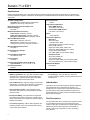
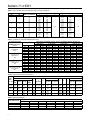
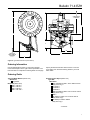
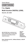
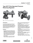
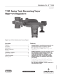
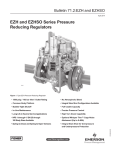
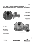
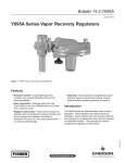
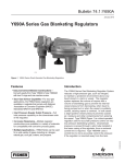
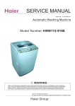
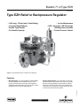
Bulletin 71.4:Type EZH
January 2015
Type EZH Relief or Backpressure Regulator
•
•
•
•
• In-Line Maintenance
1500 psig / 103 bar Inlet / Outlet Rating
Common Body Platform
Bubble Tight Shutoff
Full Usable Capacity
• NPS 1 through 4 / DN 25 through
100 Body Sizes Available
• Precise Pressure Control
P1668
Figure 1. Type EZH Relief Valve or Backpressure Regulator
Features
• Common Body Platform—The Type EZH use the same
standard Fisher® E-Body which is also used in Type EZR
pressure reducing regulator and Types EZ, ES, ED and
ET pressure reducing control valves. This will allow easy
conversion from one product to another without the need
to remove the E-Body from the pipeline.
D103574X012
• Main Diaphragm—The main diaphragm is Nitrile (NBR)
reinforced with fabric and coated with a PVC, which
protects and extends the service life of the regulator in
applications where the liquids commonly found in natural
gas pipelines tend to shorten diaphragm life.
www.fisherregulators.com
Bulletin 71.4:EZH
Specifications
Ratings and specifications for the Type EZH are listed in the Specifications section below. Specifications for specific relief
valve or backpressure regulator constructions are stamped on a nameplate attached to either the main actuator or the pilot
spring case.
Available Configurations
Type EZH: Pilot-operated relief or backpressure
regulator for low to high outlet pressure
Body Sizes, End Connection Styles and
Pressure Ratings(1)
See Table 1
Maximum Allowable Pressures(1)
Inlet Pressure: 1500 psig / 103 bar
Outlet (Casing) Pressure: 1500 psig / 103 bar
Emergency Casing Pressure: 1500 psig / 103 bar
Minimum Buildup Pressure
Main Valve: 1500 psid / 103 bar d
Pilot (Between loading pressure in pilot and
loading sense pressure): 1233 psid / 85.0 bar d
Minimum Differential Pressures
See Table 3
Relief Set Pressure Ranges
See Table 2
Flow and Sizing Coefficients
See Tables 5 and 6
Flow Capacities
See Table 7
Pilot and Filter-Regulator Flow Coefficients
Type PRX Pilot: Cg: 10.5; Cv: 0.36; C1: 29
Pressure Registration
External
Pilot Connections
1/4 NPT
Temperature Capabilities(1)
Nitrile (NBR) Version:
-20 to 180ºF / -29 to 82ºC
Fluorocarbon (FKM) Version:
0 to 180ºF / -18 to 82ºC(2)
Option
• Travel Indicator
Construction Materials
Main Valve
Main Valve Body:
Type EZH: WCC Steel
Intermediate Flange and Actuator Casings:
Steel, ASTM A350 LF2
Diaphragm Plates: Steel, ASTM A105
Diaphragm: Nitrile (NBR) with PVC coating
O-rings: Fluorocarbon (FKM)
Disk: Nitrile (NBR) or Fluorocarbon (FKM)
PRX Series Pilots
Body: Steel, ASTM 105
Trim: Stainless Steel
Elastomers: Nitrile (NBR) or Fluorocarbon (FKM)
Disk: Polyurethane (PU) or Fluorocarbon (FKM)
Approximate Weights
See Table 9
1. The pressure/temperature limits in this Bulletin and any applicable standard or code limitation should not be exceeded.
2. Type PRX Fluorocarbon (FKM) elastomer is limited to 0°F / -18°C.
• B
ubble Tight Shutoff—The Type EZH have knife-edged,
metal plug and a soft seat which provide bubble tight
shutoff for use in applications where positive shutoff is
required. For example: dead-end systems.
• In-Line Maintenance—Top entry design provides easier
maintenance. Trim parts can be inspected, cleaned and
replaced without removing the body from pipeline.
• Precise Pressure Control—The Type EZH use the
PRX Series pilot system to provide stable and accurate
pressure control.
• F
ull Pressure Rating—The Type EZH have equal inlet
and outlet pressure rating of 1500 psig / 103 bar, which
allows easier selection and requires no special startup or
shutdown procedures.
• F
ull Usable Capacity—Fisher® brand regulators are
laboratory tested. 100% of the published flow capacity
can be used with confidence.
2
• O-ring Design—The Type EZH use elastomer
O-rings instead of gaskets, reducing maintenance and
assembly time.
Introduction
Type EZH is an accurate pilot-operated, pressure-balanced,
soft-seated relief valve or backpressure regulator. It is
designed for use in high pressure natural gas transmission/
city gate stations, large capacity distribution systems and
power plant feeds. It provides smooth and reliable operation,
tight shutoff and long life.
Pilot Descriptions
The Type EZH relief valve or backpressure regulator include
a Type PRX/182 pilot mounted on the EZH Series main
valves for relief valve or backpressure regulator applications.
PRX Series pressure reducing pilots have the ability to
handle a wide range of setpoints from 29 to 1160 psig /
2.0 to 80.0 bar.
Bulletin 71.4:EZH
Principle of Operation
A pressure relief valve is a throttling pressure control device
that opens and closes to ensure the downstream pressure
does not rise above a predetermined pressure. Fisher®
relief valves cannot be used as ASME safety relief valves.
A backpressure regulator is a device that controls and
responds to changes in the upstream pressure. It functions
the same as a relief valve in that it opens on increasing
upstream pressure.
Relief Valve
As long as the inlet pressure is below the set pressure, the
pilot control spring keeps the pilot valve plug closed. Inlet
pressure passes through the restrictor and registers as
loading pressure on the main valve diaphragm chamber.
Force from the main spring, in addition to pilot loading
pressure, provide loading pressure to keep the main valve
diaphragm and plug assembly tightly shut off. When the
inlet pressure rises above the set pressure, the pressure
on the pilot diaphragm overcomes the pilot control spring
and opens the pilot valve plug. The pilot then exhausts the
loading pressure from the main valve diaphragm chamber.
The pilot continuously exhausts gas when the inlet pressure
is above the set pressure. The inlet pressure unbalance
overcomes the main spring force and opens the diaphragm
and plug assembly.
As the inlet pressure drops below the set pressure, the pilot
control spring closes the pilot valve plug and the exhaust
to atmosphere stops. Force from the main spring, along
with pilot loading pressure, pushes the diaphragm and plug
assembly onto the knife-edged seat, producing tight shutoff.
Capacity Information
Note
EZH Series flow capacities are laboratory
verified; therefore, it may be sized for 100%
flow using published capacities as shown. It is
not necessary to reduce published capacities.
Table 7 show the natural gas regulating capacities of the
Type EZH relief or backpressure regulator at selected
inlet pressures and outlet pressure settings. Flows are in
thousands of SCFH at 60°F and 14.7 psia (or in thousands
of Nm³/h at 0°C and 1.01325 bar) of 0.6 specific gravity
natural gas.
To determine equivalent capacities for air, propane, butane
or nitrogen, multiply the capacity by the following appropriate
conversion factor: 0.775 for air, 0.628 for propane, 0.548
for butane or 0.789 for nitrogen. For gases of other specific
gravities, multiply the given capacity by 0.775 and divide by
the square root of the appropriate specific gravity. Then, if
capacity is desired in Nm³/h at 0°C and 1.01325 bar, multiply
SCFH by 0.0268.
To find approximate regulating capacities at pressure
settings not given in Table 7 or to find wide-open flow
capacities for relief sizing at any inlet pressure, perform one
of the following procedures. Then convert using the factors
provided above, if necessary.
Critical Pressure Drops
For critical pressure drops (absolute outlet pressure equal
to or less than one-half of absolute inlet pressure), use the
following formula:
Backpressure Regulator
As long as inlet pressure remains below setpoint, the
pilot control spring keeps the pilot valve plug closed. Inlet
pressure passes through the upper port around the upper
portion of the valve plug and then through the hollow
passage in that valve plug. Force from the main spring,
in addition to pilot loading pressure, provide downward
loading pressure to keep the main valve diaphragm and plug
assembly tightly shut off. When inlet pressure rises above
the set pressure, pressure on the pilot diaphragm overcomes
the control spring to close the upper port and stroke the
valve plug to open the lower port. The pilot exhausts loading
pressure from the main valve diaphragm chamber. Inlet
pressure unbalance overcomes the main spring force to
open the diaphragm and plug assembly.
While the main valve is throttling, the upper port of the pilot
stays closed. The pilot exhausts only when it repositions the
main valve. As inlet pressure drops below setpoint, the pilot
control spring overcomes the diaphragm force to stroke the
valve plug down to close the lower port and open the upper
port. Force from the main spring, along with the pilot loading
pressure, pushes the diaphragm and plug assembly onto the
knife-edged seat, producing tight shutoff.
Q = (P1)(Cg)(1.29)
Non-Critical Pressure Drops
For pressure drops lower than critical (absolute outlet pressure
greater than one-half of absolute inlet pressure).
Q=
520
GT
CgP1SIN
3417
C1
P
P1
DEG
where,
Q = gas flow rate, SCFH
P1 = absolute inlet pressure, psia (P1 gauge + 14.7)
Cg = regulating or wide-open gas sizing coefficient
G = gas specific gravity of the gas
T = absolute temperature of gas at inlet, °Rankine
C1 = flow coefficient
P = pressure drop across the regulator, psi
3
Type EZH
December 2007
Bulletin 71.4:EZH
Type EZH with Type PRX-182 Pilot
SPRING
CASE VENT
PORT L
PORT S
PORT A
M1055
INLET PRESSURE
OUTLET PRESSURE
ATMOSPHERIC PRESSURE
LOADING PRESSURE
M1055
INLET PRESSURE
OUTLET PRESSURE
LOADING PRESSURE
ATMOSPHERIC PRESSURE
TYPE PRX:
S - BLEED PORT
B - SUPPLY PORT
L - LOADING PORT
A - SENSING PORT
Figure 2. Type EZH with Type PRX-182 Pilot
Table 1. Main Valve Body Sizes, End Connection Styles and Body Ratings
MAIN VALVE BODY SIZE
NPS
4
DN
1
25
2
50
3
80
4
100
MAIN VALVE BODY MATERIAL
END CONNECTION STYLE
WCC Steel
NPT or SWE
CL150 RF
CL300 RF
CL600 RF or BWE
NPT or SWE
CL150 RF
CL300 RF
CL600 RF or BWE
CL150 RF
CL300 RF
CL600 RF or BWE
CL150 RF
CL300 RF
CL600 RF or BWE
STRUCTURAL DESIGN RATING
psig
bar
1500
290
750
1500
1500
290
750
1500
290
750
1500
290
750
1500
103
20.0
51.7
103
103
20.0
51.7
103
20.0
51.7
103
20.0
51.7
103
Bulletin 71.4:EZH
Table 2. Relief Set Pressure Ranges
PILOT TYPE
PRX/182
PRX-AP/182
RELIEF SET
PRESSURE RANGE
PILOT CONTROL INFORMATION
psig
bar
Part Number
Color
29 to 116
73 to 290
217 to 609
435 to 1160
2.0 to 8.0
5.0 to 20.0
15.0 to 42.0
30.0 to 80.0
M0255220X12
M0255200X12
M0255190X12
M0273790X12
Black
Gold
Red
Clear
Wire Diameter
Free Length
In.
0.157
0.217
0.256
0.335
In.
2.16
2.01
1.97
3.94
mm
4.00
5.50
6.50
8.50
mm
55
51
50
100
Maximum
Operating Pressure
psig
bar
Maximum
Emergency Pressure
psig
bar
609
42.0
1480
102
1160
80.0
1480
102
Table 3. Minimum Differential Pressures
MAIN VALVE BODY SIZE
TYPE
EZH
NPS
DN
1
2
25
50
MINIMUM DIFFERENTIAL
For 90% Capacity
For 100% Capacity
psid
bar d
psid
bar d
15.2
1.1
15.7
1.1
12.0
0.83
13.8
0.95
3
80
10.6
0.73
12.8
0.88
4
100
15.8
1.1
16.4
1.1
Table 4. Relief Set Pressure Build-Up Table
PILOT
TYPE
SET PRESSURE CONTROL
RANGE, SPRING PART
NUMBER AND COLOR,
psig / bar
29 to 116 / 2 to 8
M0255220X12
Black
PRX/182
73 to 290 / 5 to 20
M0255200X12
Gold
217 to 609 / 14.9 to 41.7
M0255190X12
Red
PRX-AP/182
435 to 1160 / 30 to 80
M0273790X12
Clear
SET PRESSURE(1)
psig
30
60
80
100
75
100
150
200
250
225
300
400
450
450
500
600
1050
bar
2.1
4.1
5.5
6.9
5.2
6.9
10.3
13.8
17.2
15.5
20.7
27.6
31.0
31.0
34.5
41.4
72.4
BUILD-UP OVER SET
PRESSURE NEEDED
TO BEGIN OPENING
MAIN VALVE(2)
psig
bar
1.7
0.12
2.7
0.19
2.8
0.19
3.8
0.26
3.7
0.25
3.7
0.25
4.7
0.32
5.0
0.34
5.0
0.34
5.0
0.34
5.1
0.35
5.2
0.36
5.4
0.37
5.4
0.37
5.4
0.37
6.2
0.43
6.2
0.43
BUILD-UP OVER SET
PRESSURE NEEDED
TO FULLY OPEN
MAIN VALVE(3)
psig
bar
3.4
0.23
4.7
0.32
5.3
0.36
6.3
0.43
7.7
0.53
9.2
0.63
9.8
0.68
10.9
0.75
11.5
0.79
13.7
0.95
14.0
0.97
14.5
1.00
14.5
1.00
14.9
1.03
14.9
1.03
14.9
1.03
15.6
1.08
PRESSURE DROP
BELOW SET
PRESSURE NEEDED
TO RESEAT PILOT
psig
bar
0.9
0.06
0.9
0.06
0.9
0.06
0.9
0.06
1.9
0.13
1.9
0.13
1.9
0.13
1.9
0.13
1.9
0.13
2.5
0.17
2.5
0.17
2.5
0.17
2.5
0.17
2.9
0.20
3.2
0.22
3.2
0.22
3.2
0.22
1. Set pressure is defined as the pressure at which the pilot starts-to-discharge.
2. Crack point pressure of the main valve of the inlet pressure build-up over the set pressure at which the main valve starts audible flow.
3. Inlet pressure build-up over the set pressure for the main valve to achieve wide-open flow capacity.
Table 5. Type EZH Main Valve with Standard Cage Regulating Flow Coefficients
MAIN VALVE BODY SIZE
NPS
DN
1
25
2
50
3
80
4
100
TRIM, % OF CAPACITY
100
80
50
30
100
80
50
30
100
80
50
30
100
80
50
30
LINE SIZE EQUALS BODY SIZE
2:1 LINE SIZE TO BODY SIZE PIPING
Cg
Cv
C1
Cg
Cv
C1
564
436
284
172
2278
1719
1213
707
4960
3950
2550
1530
7250
5750
3510
2130
16.3
12.3
8.4
5.3
58.5
47.1
31.0
16.9
133
109
63.6
36.7
227
165
95.9
56.7
34.6
35.4
33.7
32.5
38.9
36.5
39.1
41.7
37.3
36.2
40.1
41.7
31.9
34.8
36.6
37.6
544
423
249
157
2110
1609
1177
718
4396
3294
2069
1339
7170
5630
3460
2080
15.3
10.9
6.3
4.0
62.9
50.5
33.0
18.8
143
97.2
54.7
39.8
229
165
95.5
56.2
35.5
38.7
39.7
39.1
33.5
31.9
35.6
38.2
30.8
33.9
37.80
33.6
31.3
34.1
36.2
37.0
5
Bulletin 71.4:EZH
Table 6. Type EZH Main Valve with Standard Cage IEC Sizing Coefficients
MAIN VALVE BODY SIZE
NPS
1
25
2
50
3
80
4
100
LINE SIZE EQUALS BODY SIZE
TRIM, % OF CAPACITY
DN
XT
0.61
0.72
0.69
0.66
0.73
0.84
0.97
0.99
0.88
0.83
0.99
0.99
0.63
0.76
0.85
0.88
100
80
50
30
100
80
50
30
100
80
50
30
100
80
50
30
FD
0.61
0.67
0.80
0.81
0.59
0.68
0.69
0.70
0.58
0.71
0.73
0.72
0.63
0.74
0.77
0.78
2:1 LINE SIZE TO BODY SIZE PIPING
FL
XT
0.80
0.95
0.99
0.97
0.69
0.72
0.84
0.92
0.60
0.73
0.90
0.72
0.62
0.74
0.83
0.88
0.89
FD
0.59
0.63
0.69
0.71
0.61
0.70
0.72
0.74
0.60
0.67
0.68
0.75
0.63
0.74
0.77
0.77
FL
0.89
Table 7. Capacities for Type EZH with PRX Series Pilot
Set pressure range,
Pilot Spring Part
Number and color,
psig / bar
capacities in thousands of SCFH / nm3/h OF 0.6 specific gravity natural gas
Set pressure
psig
30
60
80
100
75
100
150
200
250
225
300
400
450
450
500
600
1050
29 to 116 / 2 to 8
M0255220X12
Black
73 to 290 / 5 to 20
M0255200X12
Gold
217 t o 609 / 14.9 to 41.7
M0255190X12
Red
435 to 1160 / 30 to 80
M0273790X12
Clear
1 NPS / DN 25
bar
2.1
4.1
5.5
6.9
5.2
6.9
10.3
13.8
17.2
15.5
20.7
27.6
31.0
31.0
34.4
41.4
72.4
SCFH
36
59
75
91
72
91
130
169
207
189
246
322
360
360
398
474
815
nm3/h
0.96
1.58
2.01
2.44
1.93
2.44
3.48
4.53
5.55
5.07
6.59
8.63
9.65
9.65
10.67
12.70
21.84
2 nps / DN 50
SCFH
139
235
298
363
286
366
522
678
834
762
992
1298
1452
1452
1605
1911
3286
3 nps / DN 80
nm3/h
3.73
6.30
7.99
9.73
7.66
9.81
13.99
18.17
22.35
20.42
26.59
34.79
38.91
38.91
43.01
51.21
88.06
SCFH
307
518
654
795
628
801
1141
1482
1822
1664
2165
2833
3168
3168
3501
4167
7164
4 nps / DN 100
nm3/h
8.23
13.88
17.53
21.31
16.83
21.47
30.58
39.72
48.83
44.60
58.02
75.92
84.90
84.90
93.83
111.68
192.00
SCFH
458
756
952
1154
914
1163
1654
2148
2639
2410
3136
4102
4588
4588
5071
6035
10,375
nm3/h
12.27
20.26
25.51
30.93
24.50
31.17
44.33
57.57
70.73
64.59
84.04
109.93
122.96
122.96
135.90
161.74
278.05
Table 8. Type EZH Dimensions (See Figure 4)
Dimension, in. / mm
Body
Size,
NPS / DN
1 / 25
2 / 50
3 / 80
4 / 100
A
NPT
CL600 RF
or
CL150 RF CL300 RF
or
SWE
BWE
8.25 /
7.25 /
7.75 /
8.25 /
210
184
197
210
11.3 /
10.0 /
10.50 /
11.30 /
287
254
267
287
13.25 / 11.75 /
12.50 /
13.25 /
337
298
317
337
14.5 /
- - - - 13.9 / 353
15.5 / 394
368
C
1.50 /
38.1
1.50 /
38.1
2.00 /
50.8
2.00 /
50.8
D
(Maximum)
F
E
7.50 /
190
11.25 /
3.10 / 79
286
13.75 /
3.81 / 97
349
15.5 /
5.06 / 129
394
2.10 / 53
R
Type PRX Type PRX-AP
11.30 /
287
13.00 /
330
13.61 /
346
14.1 /
358
13.05 / 331
14.75 / 375
15.36 / 390
15.85 / 403
G
11.10 /
282
11.30 /
287
16.75 /
425
16.8 /
427
H
J
Type PRX Type PRX-AP
5.10 / 8.25 /
16.80 / 427
130
210
6.50 / 7.75 /
18.50 / 470
165
197
8.00 / 13.25 /
18.60 / 472
203
337
10.03 / 5.5 /
26.1 / 663
255
140
18.55 / 471
20.30 / 516
20.86 / 530
26.1 / 663
Table 9. Approximate Weights
Body Size, NPS / DN
6
Approximate Shipping Weight, lbs / kg
NPT
SWE
CL150 RF
CL300 RF
CL600 RF
SCH 40
1 / 25
77 / 35
77 / 35
79 / 36
83 / 38
87 / 39
77 / 35
SCH 80
77 / 35
2 / 50
136 / 62
136 / 62
139 / 63
143 / 65
150 / 68
136 / 62
136 / 62
3 / 80
390 / 177
390 / 177
394 / 179
397 / 180
410 / 186
390 / 177
390 / 177
4 / 100
----
433 / 197
451 / 205
481 / 219
514 / 234
433 / 197
433 / 197
Bulletin 71.4:EZH
R
(Trim Removal
Clearance)
h
F
G
E
D
A/2
c
(Indicator
Cover Removal
Clearance)
ERCA04507
A
J
Figure 4. Type EZH Dimensions (See Table 8)
Ordering Information
Use the Specifications section on page 2 and carefully
review the description to the right of each specification. Use
this information to complete the Ordering Guide on this page.
Specify the desired selection wherever there is a choice
to be made. Then send the Ordering Guide to your local
Sales Office.
Ordering Guide
Type and Body Material (Select One)
WCC Steel
Type EZH
Body Size (Select One)
NPS 1 / DN 25***
NPS 2 / DN 50***
NPS 3 / DN 80***
NPS 4 / DN 100***
End Connection Styles (Select One)
Type EZH
WCC Steel
NPT (available for NPS 1 and 2 / DN 25 and 50
Body sizes only)***
CL150 RF***
CL300 RF***
CL600 RF***
SWE (Available for NPS 1 and 2 / DN 25 and 50
Body Sizes only)**
BWE**
PN 16/40 (For NPS 1 and 2 / DN 25 and 50
Body Sizes only)**
PN 25/40 (For NPS 3 / DN 80
Body Size only)**
- continued -
7
Bulletin 71.4:EZH
Ordering Guide (continued)
Main Valve Disk Material (Select One)
Nitrile (NBR) (standard)***
Fluorocarbon (FKM)***
Pilot Type and Outlet Pressure Range (Select One)
Type PRX/182
29 to 116 psig / 2.0 to 8.0 bar, Black***
73 to 290 psig / 5.0 to 20.0 bar, Gold***
217 to 609 psig / 14.9 to 41.7 bar, Red***
Type PRX-AP/182
435 to 1160 psig / 30 to 80 bar, Clear***
Pilot Elastomer Material (Select One)
Nitrile (NBR) / Polyurethane (PU) (standard)***
Fluorocarbon (FKM)***
Travel Indicator (Select One)
Yes***
No***
Main Valve Replacement Parts Kit (Optional)
Yes, send one replacement parts kit to match this order.
Pilot Replacement Parts Kit (Optional)
Yes, send one replacement parts kit to match this order.
Regulators Quick Order Guide
***
**
*
Readily Available for Shipment
Allow Additional Time for Shipment
Special Order, Constructed from Non-Stocked Parts.
Consult your local Sales Office for Availability.
Specification Worksheet
Application:
Specific Use
Line Size
Fluid Type
Specific Gravity
Temperature
Does the Application Require Overpressure Protection? Yes No
Pressure:
Maximum Inlet Pressure
Minimum Inlet Pressure
Differential Pressure
Set Pressure
Maximum Flow
Accuracy Requirements:
Less Than or Equal To:
5% 10% 20% 40%
Construction Material Requirements (if known):
Availability of the product being ordered is determined by the component with the
longest shipping time for the requested construction.
Industrial Regulators
Natural Gas Technologies
TESCOM
Emerson Process Management
Regulator Technologies, Inc.
Emerson Process Management
Regulator Technologies, Inc.
Emerson Process Management
Tescom Corporation
USA - Headquarters
McKinney, Texas 75070 USA
Tel: +1 800 558 5853
Outside U.S. +1 972 548 3574
USA - Headquarters
McKinney, Texas 75070 USA
Tel: +1 800 558 5853
Outside U.S. +1 972 548 3574
USA - Headquarters
Elk River, Minnesota 55330-2445, USA
Tels: +1 763 241 3238
+1 800 447 1250
Asia-Pacific
Shanghai 201206, China
Tel: +86 21 2892 9000
Asia-Pacific
Singapore 128461, Singapore
Tel: +65 6770 8337
Europe
Selmsdorf 23923, Germany
Tel: +49 38823 31 287
Europe
Bologna 40013, Italy
Tel: +39 051 419 0611
Europe
Bologna 40013, Italy
Tel: +39 051 419 0611
Chartres 28008, France
Tel: +33 2 37 33 47 00
Asia-Pacific
Shanghai 201206, China
Tel: +86 21 2892 9499
Middle East and Africa
Dubai, United Arab Emirates
Tel: +971 4811 8100
Middle East and Africa
Dubai, United Arab Emirates
Tel: +971 4811 8100
For further information visit www.emersonprocess.com/regulators
The Emerson logo is a trademark and service mark of Emerson Electric Co. All other marks are the property of their prospective owners. Fisher is a mark owned by Fisher Controls International LLC,
a business of Emerson Process Management.
The contents of this publication are presented for informational purposes only, and while every effort has been made to ensure their accuracy, they are not to be construed as warranties or
guarantees, express or implied, regarding the products or services described herein or their use or applicability. We reserve the right to modify or improve the designs or specifications of such
products at any time without notice.
Emerson Process Management Regulator Technologies, Inc. does not assume responsibility for the selection, use or maintenance of any product. Responsibility for proper selection, use and
maintenance of any Emerson Process Management Regulator Technologies, Inc. product remains solely with the purchaser.
©Emerson Process Management Regulator Technologies, Inc., 2012, 2015; All Rights Reserved