1
Instruction Manual
PN 51-TCL-1056/rev.D
May 2011
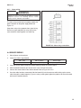
Model TCL
Total Chlorine Analyzer
1.00ppm
25.0 c
°
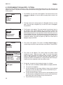
ESSENTIAL INSTRUCTIONS
WARNING
READ THIS PAGE BEFORE PROCEEDING!
ELECTRICAL SHOCK HAZARD
Rosemount Analytical designs, manufactures, and tests its
products to meet many national and international standards. Because these instruments are sophisticated technical products, you must properly install, use, and maintain
them to ensure they continue to operate within their normal
specifications. The following instructions must be adhered
to and integrated into your safety program when installing,
using, and maintaining Rosemount Analytical products.
Failure to follow the proper instructions may cause any one
of the following situations to occur: Loss of life; personal
injury; property damage; damage to this instrument; and
warranty invalidation.
• Read all instructions prior to installing, operating, and
servicing the product. If this Instruction Manual is not the
correct manual, telephone 1-800-654-7768 and the
requested manual will be provided. Save this Instruction
Manual for future reference.
• If you do not understand any of the instructions, contact
your Rosemount representative for clarification.
• Follow all warnings, cautions, and instructions marked on
and supplied with the product.
• Inform and educate your personnel in the proper installation, operation, and maintenance of the product.
• Install your equipment as specified in the Installation
Instructions of the appropriate Instruction Manual and
per applicable local and national codes. Connect all
products to the proper electrical and pressure sources.
• To ensure proper performance, use qualified personnel to
install, operate, update, program, and maintain the
product.
• When replacement parts are required, ensure that qualified people use replacement parts specified by
Rosemount. Unauthorized parts and procedures can
affect the product’s performance and place the safe operation of your process at risk. Look alike substitutions may
result in fire, electrical hazards, or improper operation.
• Ensure that all equipment doors are closed and protective covers are in place, except when maintenance is
being performed by qualified persons, to prevent electrical shock and personal injury.
Making cable connections to and servicing
this instrument require access to shock hazard level voltages which can cause death or
serious injury.
Be sure to disconnect all hazardous voltage
before opening the enclosure.
Relay contacts made to separate power
sources must be disconnected before servicing.
Electrical installation must be in accordance
with the National Electrical Code
(ANSI/NFPA-70) and/or any other applicable
national or local codes.
Unused cable conduit entries must be
securely sealed by non-flammable closures
to provide enclosure integrity in compliance
with personal safety and environmental protection requirements.
The unused conduit openings need to be
sealed with NEMA 4X or IP65 conduit plugs
to maintain the ingress protection rating
(IP65).
For safety and proper performance this
instrument must be connected to a properly
grounded three-wire power source.
Proper relay use and configuration is the
responsibility of the user.
No external connection to the instrument of
more than 69VDC or 43V peak allowed with
the exception of power and relay terminals.
Any violation will impair the safety protection
provided
Do not operate this instrument without front
cover secured. Refer installation, operation
and servicing to qualified personnel.
WARNING
This product is not intended for use in the light industrial, residential or commercial environment, per the
instrument’s certification to EN50081-2.
Emerson Process Management
2400 Barranca Parkway
Irvine, CA 92606 USA
Tel: (949) 757-8500
Fax: (949) 474-7250
http://www.raihome.com
© Rosemount Analytical Inc. 2011
DANGER
CAUTION
HAZARDOUS AREA INSTALLATION
SENSOR/PROCESS APPLICATION COMPATIBILITY
Installations near flammable liquids or in hazardous area locations must be carefully evaluated by qualified on site safety personnel.
This device is not Intrinsically Safe or
Explosion Proof.
Wetted materials may not be compatible
with process composition and operating
conditions. Application compatibility is
entirely the responsibility of the user.
To secure and maintain an intrinsically safe
installation, the certified safety barrier, transmitter, and sensor combination must be
used. The installation system must comply
with the governing approval agency (FM,
CSA or BASEEFA/CENELEC) hazardous
area classification requirements. Consult
your analyzer/transmitter instruction manual
for details.
Proper installation, operation and servicing
of this device in a Hazardous Area Installation is entirely the responsibility of the user.
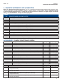
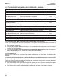
About This Document
This manual contains instructions for installation and operation of the Model TCL1056
Total Chlorine Analyzer.
The following list provides notes concerning all revisions of this document.
Rev. Level
Date
Notes
A
7/07
This is the initial release of the product manual. The manual
has been reformatted to reflect the Emerson documentation
style and updated to reflect any changes in the product offering.
B
11/07
Page 3 additions to 1.3 Specifications, page 5 changes to the
Analyzer (option selection) table, page 14 updated the caution
box and page 15 updated section 4.3.3.
C
7/10
Updated DNV logo.
D
5/11
Revised Sec. 1, specs 1.3, replaced fig 3-3, revised sec. 4.3.3
wiring, replaced fig 4.4. add to digital communication sec 8.0,
revise sec. 11.6.
MODEL TCL
TABLE OF CONTENTS
MODEL TCL
TOTAL CHLORINE ANALYZER
TABLE OF CONTENTS
Section
1.0
1.1
1.2
1.3
1.4
1.5
1.6
Title
DESCRIPTION AND SPECIFICATIONS.................................................................
Features and Applications ......................................................................................
Specifications — Sample Conditioning System ......................................................
Specifications — Model 1056 Analyzer ...................................................................
Specifications — Model 499ACL-02 Sensor............................................................
Performance Specifications — Complete System .................................................
Ordering Information and Accessories ...................................................................
Page
1
2
3
3
4
4
5
2.0
PRINCIPLES OF OPERATION ..............................................................................
7
3.0
3.1
3.2
INSTALLATION ......................................................................................................
Unpacking and Inspection ......................................................................................
Installation................................................................................................................
8
8
8
4.0
4.1
4.2
4.3
4.4
WIRING ..................................................................................................................
Prepare Analyzer Conduit Openings .......................................................................
Provide Power to the Sample Conditioning System ................................................
Make Power, Alarm, Output, and Sensor Connections in the Analyzer ...................
Sensor Wiring ..........................................................................................................
13
13
13
14
15
5.0
5.1
5.2
5.3
5.4
START-UP ..............................................................................................................
Prepare the Reagent ...............................................................................................
Zero the Sensor .......................................................................................................
Start Sample Flow....................................................................................................
Begin Operation and Calibrate the Sensor ..............................................................
19
19
19
19
19
6.0
6.1
6.2
6.3
6.4
6.5
6.6
DISPLAY AND OPERATION ..................................................................................
Display .....................................................................................................................
Keypad.....................................................................................................................
Programming the Analyzer — Tutorial ....................................................................
Security....................................................................................................................
Using Hold ...............................................................................................................
Configuring the Main Display...................................................................................
20
20
21
22
23
24
25
7.0
7.1
7.2
7.3
7.4
7.5
7.6
7.7
7.8
PROGRAMMING THE ANALYZER .......................................................................
General ....................................................................................................................
Default Setting .........................................................................................................
Configuring, Ranging and Simulating Outputs........................................................
Configuring Alarms and Assigning Setpoints ...........................................................
Configuring the Measurement .................................................................................
Configuring Temperature Related Settings ..............................................................
Configuring Security Settings...................................................................................
Resetting the Analyzer.............................................................................................
26
26
26
29
32
36
38
39
40
i
MODEL TCL
TABLE OF CONTENTS
TABLE OF CONTENTS CONT'D.
8.0
DIGITAL COMMUNICATIONS ................................................................................
41
9.0
9.1
9.2
9.3
9.4
CALIBRATION .......................................................................................................
Introduction ..............................................................................................................
Calibrating Temperature ..........................................................................................
Calibrating Total Chlorine.........................................................................................
Calibrating Analog Outputs ......................................................................................
42
42
42
44
47
10.0
10.1
10.2
10.3
10.4
MAINTENANCE .....................................................................................................
Analyzer...................................................................................................................
Total Chlorine Sensors.............................................................................................
Sample Conditioning System...................................................................................
Simulating Inputs .....................................................................................................
49
50
50
52
54
11.0
11.1
11.2
11.3
11.4
11.5
11.6
TROUBLESHOOTING ...........................................................................................
Overview..................................................................................................................
Using the Diagnostic Feature ..................................................................................
Troubleshooting When a Fault Message is Showing...............................................
Troubleshooting When a Warning Message is Showing .........................................
Troubleshooting When no Error Message is Showing............................................
Simulating Temperature...........................................................................................
59
59
59
60
62
63
67
12.0
12.1
12.2
12.3
RETURN OF MATERIAL ........................................................................................
General ....................................................................................................................
Warranty Repair.......................................................................................................
Non-Warranty Repair ...............................................................................................
68
68
68
68
LIST OF TABLES
Number
Title
Page
7-1
Default Settings ......................................................................................................
27-28
10-1
Spare Parts .............................................................................................................
51
10-2
Replacement Parts and Reagent for Sample Conditioning System .......................
58
ii
MODEL TCL
TABLE OF CONTENTS
LIST OF FIGURES
Number
2-1
3-1
3-2
3-3
3-4
3-5
4-1
4-2
4-3
4-4
4-5
6-1
6-2
6-3
6-4
6-5
7-1
7-2
7-3
9-1
9-2
10-1
10-2
10-3
10-4
10-5
10-6
10-7
10-8
10-9
10-10
10-11
10-12
10-13
10-14
10-15
10-16
10-17
Title
Schematic of Sample Conditioning System and Analyzer ....................................
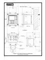
Panel Mount Dimensions .......................................................................................
Pipe and Wall Mounting Dimensions ......................................................................
Installing the Sample Conditioning Enclosure.........................................................
TCL Case Dimensions ............................................................................................
Reagent Tubing Assembly ......................................................................................
Power Wiring ..........................................................................................................
Location of power connector on power supply board. ............................................
Analog output connections......................................................................................
Wiring Sensor with Optimum EMI/RFI or Variopol Cable to Model 1056 Analyzer....
Wiring Sensor with Standard Cable to Model 1056 Analyzer..................................
Main Display ..........................................................................................................
Programming Screen Showing Item List.................................................................
Arrow Bar ............................................................................................................................................
Analyzer keypad ....................................................................................................
Navigation keys.......................................................................................................
High Alarm Logic ....................................................................................................
Low Alarm Logic......................................................................................................
Operation of the interval timer.................................................................................
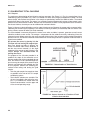
Determination of Total Chlorine ..............................................................................
Sensor Current as a Function of Total Chlorine Concentration ..............................
Sensor Board Connections ....................................................................................
Sensor Parts ...........................................................................................................
Replacing Reagent Tubing......................................................................................
Replacing Sample Tubing .......................................................................................
Peristaltic Pump Tubing ..........................................................................................
Pump Cover ............................................................................................................
Removing the Cover ...............................................................................................
Inserting New Tube .................................................................................................
Replace the Cover ..................................................................................................
Bottom of the Cover ................................................................................................
Tracks .....................................................................................................................
Disconnection .........................................................................................................
Removal of Screws .................................................................................................
Connect the Air Inlet and Outlet Tubing to the Air Pump.........................................
Schematic ...............................................................................................................
Remove the Air Inlet Fitting.....................................................................................
Slide Pump Assembly Out of the Airp Pump Body..................................................
iii
Page
7
9
10
11
12
12
13
14
15
16
16
20
20
20
21
21
33
33
33
44
44
49
51
52
53
54
54
54
54
55
55
55
56
56
56
56
57
57
MODEL TCL
SECTION 1
DESCRIPTION AND SPECIFICATIONS
SECTION 1.
DESCRIPTION AND SPECIFICATIONS
Model TCL Sample Conditioning System
•
•
•
•
NO METAL WETTED PARTS. Ideal for seawater.
LOW SAMPLE FLOW (about 15 mL/minute) means little waste.
REAGENT-BASED SYSTEM measures true total chlorine.
FIVE GALLONS OF REAGENT lasts two months.
Model 1056 Chlorine Analyzer
•
•
•
•
LARGE, PROGRAMMABLE, BACK-LIT DISPLAY with easy to use interface.
TWO INDEPENDENT ANALOG OUTPUTS.
FOUR FULLY PROGRAMMABLE RELAYS optional.
DIGITAL COMMUNICATIONS (HART OR PROFIBUS DP) optional.
Model 499A CL-02 Sensor
• MEMBRANE-COVERED AMPEROMETRIC SENSOR.
• NO TOOLS REQUIRED to change membrane.
• MAINTENANCE TAKES ONLY A FEW MINUTES a month.
• VARIOPOL CONNECTOR OPTION allows the sensor to be replaced without removing and
rewiring cable.
1.1 FEATURES
MODEL TCL SAMPLE CONDITIONING SYSTEM
The sample conditioning system permits a single sensor to measure total chlorine in water. The sample conditioning system continuously injects a solution of acetic
acid (vinegar) and potassium iodide into the sample.
The acid lowers the pH to between 3.5 and 4.5 and
allows total chlorine in the sample to quantitatively react
with the potassium iodide to produce iodine. The sensor
measures the iodine concentration, and the analyzer
displays the total oxidant concentration in ppm as Cl2.
MODEL 1056 CHLORINE ANALYZER
lyzer is through a membrane keypad. A back-lit, six
line display shows the total chlorine reading and temperature in 0.6 inch (15 mm) high characters. The display can be customized to show other information, for
example, output signal and diagnostics.
Menu screens for calibrating and programming are
simple an intuitive. Plain language prompts in six languages guide the user through procedures.
Information and diagnostic screens as well as basic
trouble-shooting guidelines are available at the touch
of a button.
The Model 1056-24 chlorine analyzer is designed for
the continuous determination of chlorine in water. It is
used with the Model 499ACL-02 sensor and TCL sample conditioning system.
The Model 1056 has two isolated, continuously variable 4-20 mA outputs. Outputs can be assigned to
total chlorine concentration or to temperature. Digital
communications, HART or Profibus DP, are available
as options.
The Model 1056 analyzer is housed in a weatherproof,
corrosion-resistant, NEMA 4X enclosure. It is suitable
for wall, panel, or pipe mounting. Operation of the ana-
Four fully programmable alarm relays are available as
an option. Relays can be assigned to total chlorine
concentration or temperature. A relay can also be
1
MODEL TCL
used to signal a fault condition. A fault alarm activates
when an analyzer or sensor fault occurs.
When used for the determination of total chlorine, the
Model 1056 analyzer is a single input instrument. The analyzer is also available in a dual input version, where the
second input can be pH, conductivity, dissolved oxygen,
chlorine, or turbidity. For more information about the dual
input option, refer to product data sheet PDS 71-1056.
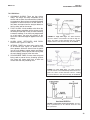
MODEL 499A CL-02 SENSOR
The Model 499ACL-02 total chlorine sensor is used in the
TCL sample conditioning system. Although the sensor is
called a chlorine sensor, it really measures iodine. The
iodine comes from the reaction between oxidants in the
sample and the acetic acid/potassium iodide reagent added
by the sample conditioning system.
The sensor consists of a gold cathode and a silver anode
in an electrolyte solution. A silicone membrane, permeable
to iodine, is stretched over the cathode. The analyzer
applies a voltage to the cathode sufficiently negative to
reduce all the iodine reaching it. Because the concentra-
2
SECTION 1
DESCRIPTION AND SPECIFICATIONS
tion of iodine in the sensor is always zero, a concentration
gradient continuously forces iodine from the sample
through the membrane into the sensor.
The reduction of iodine in the sensor generates a current
directly proportional to the diffusion rate of iodine through
the membrane, which is directly proportional to the concentration of iodine in the sample. Because the iodine concentration depends on the amount of total chlorine in the
sample, the sensor current is ultimately proportional to the
total chlorine concentration.
The permeability of the membrane to iodine is a function of
temperature. A Pt100 RTD in the sensor measures the temperature, and the analyzer uses the temperature to compensate the total chlorine reading for changes in membrane
permeability.
Sensor maintenance is fast and easy. Replacing the membrane requires no special tools or fixtures. Simply place the
membrane assembly on the cathode and screw the retainer
in place. Installing a new membrane and replenishing the
electrolyte takes only a few minutes.
MODEL TCL
SECTION 1
DESCRIPTION AND SPECIFICATIONS
1.2 SPECIFICATIONS — SAMPLE CONDITIONING SYSTEM
GENERAL
SAMPLE REQUIREMENTS
Enclosure: Fiberglass reinforced polyester, NEMA 3
(IP53) suitable for marine environments
Dimensions: 14.5 x 13.0 x 8.6 in. (369 x 329 x 218 mm)
Mounting: Wall
Ambient Temperature: 32° - 122°F (0 - 50°C)
Ambient Humidity: 0 - 90% (non-condensing)
Power: 115 Vac, 6.9 W, 50/60 Hz;
230 Vac, 7.0 W, 50/60 Hz
Hazardous Location: The TCL sample conditioning system has no hazardous location approvals.
Pumps:
EN 809:1998
Weight/Shipping Weight: 14 lb/16 lb (6.5 kg/7.5 kg)
Inlet Connection: compression fitting, accepts 1/4 in. OD
tubing
Drain Connection: 3/4 in. barbed fitting (must drain to
open atmosphere)
Inlet Pressure: <100 psig (791 kPa abs)
Flow: at least 0.25 gph (15 mL/min)
Temperature: 32 - 122°F (0 - 50°C)
Total Alkalinity: <300 mg/L as CaCO3. For samples containing <50 mg/L alkalinity, consult the factory.
SAMPLE CONDITIONING SYSTEM
Reagent: Potassium iodide in vinegar.
Reagent Usage: 5 gallons lasts approximately 60 days.
Reagent Pump: Fixed speed peristaltic pump, about
0.2 mL/min
Sample Pump: Fixed speed peristaltic pump, about 11 mL/min
1.3 SPECIFICATIONS — MODEL 1056 ANALYZER
Case: Polycarbonate NEMA 4X/CSA 4 (IP65).
Dimensions: 6.10 x 6.10 x 5.15 in. (155 x 155 x 131 mm)
Conduit openings: Accepts PG13.5 or 1/2 in. conduit
fittings
Display: Monochromatic back-lit LCD. Main character
height 0.6 in (15mm). Display is user-programable
Languages: English, German, Italian, Spanish, French,
Portuguese
Ambient temperature and humidity: 32 to 131°F (0 to
55°C); RH 5 to 95% (con-condensing)
Storage temperature: -4 to 140°F (-20°C and 60°C)
Power: Code -01: 115/230 VAC ±15%, 50/60 Hz. 10 W.
Code -03: 85 to 265 VAC, 47.5 to 65.0 Hz, 15 W
(includes four relays)
Equipment protected by double insulation
Hazardous Location Approvals - Applies to analyzer
only.
Class I, Division 2, Groups A, B, C, & D
Class Il, Division 2, Groups E, F, & D
Class Ill T4 Tamb= 50°C
RFI/EMI:
LVD:
EN-61326
EN-61010-1
Outputs: Two 4-20 mA or 0-20 mA isolated outputs.
Continuously adjustable. Linear or logarithmic.
Maximum load 550 ohms. Output dampening with
time constant of 5 sec is user-selectable.
Alarms relays (analyzer option -03 only): Four alarm
relays for process measurement(s) or temperature.
Any relay can be configured as a fault alarm instead of
a process alarm. Each relay can be configured independently and each can be programmed with interval
timer settings.
Relays: Form C, SPDT, epoxy sealed
Relay Contact ratings:
5 A at 28 VDC or 300 VAC (resistive)
1/8 HP at 120/240 VAC.
Terminal Connections Rating: Power connector
(3-leads): 18-12 AWG wire size. Current output connectors (2-leads): 24-16 AWG wire size. Alarm relay
terminal blocks: 18-16 AWG wire size
Weight/Shipping Weight: (rounded up to nearest lb or
nearest 0.5 kg): 1.5 kg (3 lb)/2.0 kg (4 lb)
Evaluated to the ANSI/UL Standards. The ‘C’ and ‘US’ indicators adjacent to the CSA Mark signify that the product has
been evaluated to the applicable CSA and ANSI/UL
Standards, for use in Canada and the U.S. respectively
3
MODEL TCL
SECTION 1
DESCRIPTION AND SPECIFICATIONS
1.4 SPECIFICATIONS — MODEL 499ACL-02 SENSOR
Wetted Parts: Gold, Noryl®1 (PPO), Viton®2, EPDM, Silicone
Dimensions: 1.0 x 5.6 in. (25.4 x 143 mm)
Cable: 25 ft. (7.6m) standard
Pressure Rating: 0 to 65 psig (101 to 549 kPa)
Temperature Rating: 32 to 122°F (0 to 50°C)
Electrolyte Capacity: Approximately 25 mL
Electrolyte Life: Approximately 4 months
Weight/Shipping Weight: 1 lb/3 lb (0.5 kg/1.5 kg)
1 Noryl is a registered trademark of General Electric.
2 Viton is a registered trademark of DuPont Performance Elastomers.
1.5 PERFORMANCE SPECIFICATIONS — COMPLETE SYSTEM
Linear Range: 0 to 20 ppm (mg/L) as Cl2 (for higher ranges, consult factory)
Linearity (per ISO 15839): 0-10 ppm: 2%; 0-20 ppm: 3%
Response Time: Following a step change in concentration, the reading reaches 90% of final value within 7 minutes at
25°C.
Drift: At about 1.5 ppm in clean water and constant temperature, drift is typically less 0.05 ppm over two weeks.
Detection Limit (per ISO 15839): 0.02 ppm (mg/L) in clean water at room temperature
4
MODEL TCL
SECTION 1
DESCRIPTION AND SPECIFICATIONS
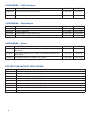
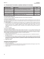
1.6 ORDERING INFORMATION AND ACCESSORIES
Model TCL Reagent-Based Chlorine System. The TCL is used for the continuous determination of total chlorine in water.
The TCL consists of a sample conditioning system, a reagent carboy, a sensor, and an analyzer. Reagents must be
ordered separately. Regent kits for 0-5 ppm and 0-10 ppm chlorine are available. For higher ranges, consult the
factory. See ACCESSORIES - Sample Conditioning System.
MODEL
TCL
REAGENT-BASED CHLORINE SYSTEM
CODE
11
12
POWER (required selection)
115 V 50/60 Hz
230 V 50/60 Hz
CODE
270
271
272
273
274
275
ANALYZER (optional selection)
1056-01-24-38-AN analyzer, no alarm relays, analog outputs
1056-01-24-38-HT analyzer, no alarm relays, HART
1056-01-24-38-DP analyzer, no alarm relays, Profibus DP
1056-03-24-38-AN analyzer, with alarm relays, analog outputs
1056-03-24-38-HT analyzer, with alarm relays, HART
1056-03-24-38-DP analyzer, with alarm relays, Profibus DP
CODE
30
31
32
SENSOR (optional selection)
499ACL-02-54 sensor with standard cable
499ACL-02-54-60 sensor with optimum EMI/RFI cable
499ACL-02-54-VP sensor with Variopol 6.0 fitting (interconnecting cable must be ordered separately)
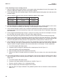
ACCESSORIES — SAMPLE CONDITIONING SYSTEM
PN
24134-00
24134-01
9160578
9322052
24153-00
9100204
9100132
9380094
9380095
9380091
24151-00
24135-00
9380090
9380093
9380092
24152-00
PN
Description
Air pump, 115 Vac, 50/60 Hz
Air pump, 230 Vac, 50/60 Hz
Air pump repair kit
Check valve for air injection line
Carboy for reagent, 5 gal/19 L, includes cap
Fuse, 0.25 A, 250 V, 3AG, slow blow for option -11 (115 Vac)
Fuse, 0.125 A, 250 V, 3AG, slow blow for option -12 (230 Vac)
Reagent pump, 115 Vac, 50/60 Hz
Reagent pump, 230 Vac, 50/60 Hz
Reagent pump replacement tubing
Reagent tubing replacement kit
Reagent uptake tubing, 6 ft (1.8 m), includes weight
Sample pump, 115 Vac, 50/60 Hz
Sample pump, 230 Vac, 50/60 Hz
Sample pump replacement tubing
Sample tubing replacement kit
Description
1
1
1
1
4
1
1
1
1
1
1
1
1
1
1
1
Weight*
lb (0.5 kg)
lb (0.5 kg)
lb (0.5 kg)
lb (0.5 kg)
lb (1.5 kg)
lb (0.5 kg)
lb (0.5 kg)
lb (0.5 kg)
lb (0.5 kg)
lb (0.5 kg)
lb (0.5 kg)
lb (0.5 kg)
lb (0.5 kg)
lb (0.5 kg)
lb (0.5 kg)
lb (0.5 kg)
Ship Weight**
1 lb (0.5 kg)
1 lb (0.5 kg)
1 lb (0.5 kg)
1 lb (0.5 kg)
5 lb (2.0 kg)
1 lb (0.5 kg)
1 lb (0.5 kg)
2 lb (1 kg)
2 lb (1 kg)
2 lb (1 kg)
2 lb (1 kg)
2 lb (1 kg)
2 lb (1 kg)
2 lb (1 kg)
2 lb (1 kg)
2 lb (1 kg)
Weight*
Ship Weight**
24165-00
Acetic acid, 2 x 2.5 gal (9.5 L) bottles/case, with 25 g potassium iodide
(0-5 ppm total chlorine)
45 lb (20.5 kg)
48 lb (22.0 kg)
24165-01
Acetic acid, 2 x 2.5 gal (9.5 L) bottles/case, with 50 g potassium iodide
(0-10 ppm total chlorine)
45 lb (20.5 kg)
48 lb (22.0 kg)
24164-00
Potassium iodide, 25 g, sufficient for 5 gallons (19 L) of vinegar
(0-5 ppm total chlorine)
1 lb (0.5 kg)
1 lb (0.5 kg)
24164-01
Potassium iodide, 50 g, sufficient for 5 gallons (19 L) of vinegar
(0-10 ppm total chlorine)
1 lb (0.5 kg)
1 lb (0.5 kg)
*Weights are rounded up to the nearest whole pound or 0.5 kg.
5
ACCESSORIES — 1055-24 Analyzer
PN
9240048-00
23820-00
DESCRIPTION
WEIGHT*
SHIP WEIGHT*
Tag, stainless steel, specify marking
1 lb (0.5 kg)
1 lb (0.5 kg)
Pipe mounting kit
2 lb (1.0 kg)
3 lb (1.5 kg)
WEIGHT*
SHIP WEIGHT*
ACCESSORIES — 54eA Analyzer
PN
DESCRIPTION
2002577
Wall and two inch pipe mounting kit
2 lb (1.0 kg)
3 lb (1.5 kg)
23545-00
Panel mounting kit
23554-00
Cable glands, kit (Qty 5 of PG 13.5)
2 lb (1.0 kg)
1 lb (0.5 kg)
3 lb (1.5 kg)
1 lb (0.5 kg)
9240048-00
Stainless steel tag (specify marking)
1 lb (0.5 kg)
1 lb (0.5 kg)
WEIGHT*
SHIP WEIGHT*
ACCESSORIES — Sensor
PN
DESCRIPTION
23501-02
Total Chlorine Membrane, includes one membrane assembly and
one O-ring
1 lb (0.5 kg)
1 lb (0.5 kg)
23502-02
Total Chlorine Membrane Kit, includes 3 membrane assemblies and
three O-rings
1 lb (0.5 kg)
1 lb (0.5 kg)
9210438
Total Chlorine Sensor Fill Solution, 4 oz (120 mL)
1 lb (0.5 kg)
2 lb (1.0 kg)
*Weights are rounded up to the nearest whole pound or 0.5 kg.
FOR FIRST TIME VARIOPOL INSTALLATIONS
PART #
DESCRIPTION
23747-06
Interconnecting cable, VP 6, 2.5 ft (0.8 m)
23747-04
Interconnecting cable, VP 6, 4 ft (1.2m)
23747-02
Interconnecting cable, VP 6, 10 ft (3.0 m)
23747-07
Interconnecting cable, VP 6, 15 ft (4.6 m)
23747-08
Interconnecting cable, VP 6, 20 ft (6.1 m)
23747-09
Interconnecting cable, VP 6, 25 ft (7.6 m)
23747-10
Interconnecting cable, VP 6, 30 ft (9.1 m)
23747-03
Interconnecting cable, VP 6, 50 ft (15.2 m)
23747-11
Interconnecting cable, VP 6, 100 ft (30.5 m)
6
MODEL TCL
SECTION 2
PRINCIPLES OF OPERATION
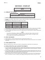
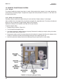
SECTION 2. PRINCIPLES OF OPERATION
Total chlorine by definition is the iodine produced in a sample when it is treated with
potassium iodide at a pH between 3.5 and 4.5.
Typically, acetic acid (or vinegar) is used to
adjust the pH.
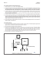
The total chlorine analyzer consists of a sample conditioning system, which injects the
reagent into the sample, and a sensor and
analyzer, which measure the amount of iodine
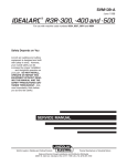
produced. Figure 2-1 shows the sample conditioning system. The sample enters the sample
conditioning enclosure and flows to an overflow sampler from which the sample pump
takes suction. Excess sample drains to waste.
At the same time, the reagent pump draws
reagent, a solution of potassium iodide in
vinegar, from the reagent carboy and injects it
into the suction side of the sample pump. The
sample and reagent mix as they pass through
the pump, and total chlorine in the sample is
converted to the chemically equivalent amount
of iodine. The flow rates are 11 mL/min for the
sample and 0.2 mL/min for the reagent.
FIGURE 2-1. Schematic of Sample Conditioning
System and Analyzer.
The treated sample next enters the flow cell. Bubbles injected into the flow cell produce turbulence, which
improves the stability of the reading. A membrane-covered amperometric sensor in the flow cell measures the
concentration of iodine. The analyzer receives the raw signal from the sensor and displays the concentration of
total chlorine. Display units are ppm (mg/L) chlorine as Cl2. The treated sample leaves the flow cell and drains
to waste along with the excess sample.
7
MODEL TCL
SECTION 3
INSTALLATION
SECTION 3. INSTALLATION
3.1 UNPACKING AND INSPECTION
Inspect the shipping containers. If there is damage, contact the shipper immediately for instructions. Save the
boxes. If there is no apparent damage, unpack the containers. Be sure all items shown on the packing list are present. If items are missing, notify Rosemount Analytical immediately.
3.2 INSTALLATION.
3.2.1 General Information
1. Although the analyzer and sample conditioning system are suitable for outdoor use, do not install them in direct
sunlight or in areas of extreme temperature.
CAUTION
The TCL Total Chlorine sample conditioning system
is NOT suitable for use in hazardous areas.
2. Install the analyzer and sample conditioning system in an area where vibration and electromagnetic and radio
frequency interference are minimized or absent.
3. Keep the analyzer and sensor wiring at least one foot from high voltage conductors. Be sure there is easy
access to the analyzer and sample conditioning system.
4. The analyzer is suitable for panel, pipe or wall mounting. The sample conditioning enclosure must be mounted on a wall. Provide adequate room beneath the enclosure for the 5-gallon reagent carboy.
5. Be sure that the distance between the analyzer and sample conditioning cabinet does not exceed the length
of the sensor cable.
3.2.2 Install the Analyzer
1. Refer to the appropriate figure for installation details.
Type of Mounting
Figure
Panel
3-1
Wall or Pipe
3-2
2. See section 4.1 for more information about the conduit openings.
3. See Section 4.2 for wiring instructions.
8
MODEL TCL
SECTION 3
INSTALLATION
INCH
MILLIMETER
17.13
1.1
126.4
5.0
154.9
6.1
154.9
6.1
Front View
Side View
( 126.4
5.0 )
76.2
3.0
41.4
1.6
Bottom View
152.73
6.0
FIGURE 3-1 PANEL MOUNTING DIMENSIONS
9
INCH
MILLIMETER
154.9
6.1
Wall / Surface Mount
102
4.0
232
9.1
33.5
1.3
130
5.1
187
7.4
154.9
6.1
165
6.5
Side View
Front View
Pipe Mount
232
9.1
Bottom View
33.5
1.3
130
5.1
80.01
3.2
45.21
1.8
165
6.5
108.9
4.3
Side View
71.37
2.8
FIGURE 3-2 PIPE AND WALL MOUNTING DIMENSIONS
(Mounting bracket PN:23820-00)
10
MODEL TCL
SECTION 3
INSTALLATION
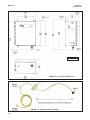
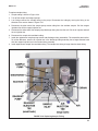
3.2.3 Install the Sample Conditioning Enclosure
1. Refer to Figures 3-3, 3-4, and 3-5 for installation details.
2. Connect the sample line to the sample conditioning system. Use ¼-inch OD hard plastic or stainless steel tubing.
If dechlorinated water is being measured, provide a way for occasionally substituting a chlorinated water sample
for the dechlorinated sample. Chlorinated water is needed to calibrate the sensor and to check its response.
3. If a grab sample tap is not already available, install one in the process piping. Choose a point as close as possible to the sample line supplying the TCL. Be sure that opening the sample valve does not appreciably alter
the flow of sample to the instrument.
4. Connect the drain to a length of ¾-inch ID flexible plastic tubing. The sample must drain to open atmosphere.
5. Find the reagent tubing and fitting in the plastic bag taped to the inside of the enclosure door. Screw the
reagent fitting onto the bulkhead fitting at the bottom left of the enclosure. Pass the reagent tubing through the
hole in the carboy cap. Be sure the plastic weight will be inside the carboy when the cap is in place. Attach the
reagent tubing to the barbed connector. See Figure 3-5.
6. Place the blue plastic carboy beneath the enclosure. Screw the cap and tubing assembly on to the carboy. To
prepare reagent, see Section 5.2.
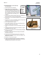
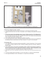
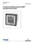
3.2.4 Install the Sensor
1. From inside the sample conditioning enclosure, thread the sensor cable or VP cable through the gland on the
upper left side. Leave about one foot of cable inside the enclosure.
2. Wire the cable to the analyzer. Refer to Section 4.4.
3. Remove the nut and adapter from the flow cell. Slip the nut over the end of the sensor. Thread the adapter
onto the sensor. Hand tighten only. If you are using a VP cable, connect the cable to the sensor. The connector and receptacle are keyed to ensure proper mating. Once the key has slid into place, tighten the connection by turning the knurled ring clockwise. Remove the protective cap from the end of the sensor.
4. Insert the sensor in the flow cell. Hand tighten the nut.
analyzer
process piping
sensor cable
sample inlet 1/4
inch OD tubing
TCL
enclosure
drain
3/4 inch ID barbed fitting
sample tap
reagent
bottle
FIGURE 3-3. Installing the Sample Conditioning Enclosure
11
MODEL TCL
SECTION 3
INSTALLATION
INCH
MILLIMETER
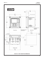
FIGURE 3-4. TCL Case Dimensions
FIGURE 3-5. Reagent tubing assembly
12
MODEL TCL
SECTION 4
WIRING
SECTION 4. WIRING
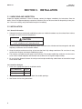
4.1 PREPARE ANALYZER CONDUIT OPENINGS
The analyzer enclosure has six conduit openings. Four conduit openings are fitted with conduit plugs.
Conduit openings accept 1/2-inch conduit fittings or PG 13.5 cable glands. To keep the case watertight, block
unused openings with NEMA 4X or IP65 conduit plugs.
NOTE
Use watertight fittings and hubs that comply with the requirements of UL514B. Connect the conduit hub to the
conduit before attaching the fitting to the analyzer (UL508-26.16).
4.2 PROVIDE POWER TO THE SAMPLE CONDITIONING SYSTEM
WARNING
RISK OF ELECTRICAL SHOCK
Electrical installation must be in accordance with the National Electrical Code
(ANSI/NFPA-70) and/or any other applicable national or local code.
NOTE
Provide a switch or breaker to disconnect the sample conditioning cabinet from the
main power supply. Install the switch or breaker near the unit and identify if as the
disconnecting device for the sample conditioning system.
1. Be sure the pump switches on the wiring access panel are in the off position.
2. Remove the four screws securing the wiring access panel. Pull the panel out of the way to reveal the power
terminal strip.
3. Insert the power cable through the strain relief connection labeled power (see Figure 3-4). Wire the power
cable to the terminal strip as shown in Figure 4-1. Do not apply 230 Vac power to a 115 Vac TCL (Model option
-11). Doing so will damage the instrument.
4. Leave the pump power switches off until ready to start up the unit. See Section 5.
Model option -11 115 Vac only
Model option -12 230 Vac only
FIGURE 4-1. Power Wiring
13
MODEL TCL
SECTION 4
WIRING
4.3 MAKE POWER, ALARM, OUTPUT, AND SENSOR CONNECTIONS IN THE ANALYZER
WARNING
RISK OF ELECTRICAL SHOCK
Electrical installation must be in accordance with the National Electrical Code
(ANSI/NFPA-70) and/or any other applicable national or local code.
4.3.1 Power
Wire AC mains power to the power supply board, which is mounted vertically on the left hand side of the analyzer
enclosure. The power connector is at the top of the board. Unplug the connector from the board and wire the power
cable to it. Lead connections are marked on the connector. (L is live or hot; N is neutral, the ground connection
has the standard symbol.)
AC power wiring should be 14 gauge or greater. Run the power wiring through the conduit opening nearest the
power terminal. Provide a switch or breaker to disconnect the analyzer from the main power supply. Install the
switch or breaker near the analyzer and label it as the disconnecting device for the analyzer.
CAUTION
If your 1056 analyzer does not have alarm relays (options -270, -271, or -272) you must set the black and red
AC power switch located below the power terminal to the correct AC voltage. The analyzer is shipped with the
switch in the 230 VAC position. For operation at 110-120 VAC, slide the switch upward so that 115 VAC is showing.
If your 1056 analyzer has alarm relays (options -273, -274, or -275) there is no switch setting to make. The
analyzer automatically detects the AC voltage.
4.3.2 Analog output wiring
Two analog current outputs are located on the
main circuit board, which is attached to the
inside of the enclosure door. Figure 4-3 shows
the location of the terminals. The connectors can
be detached for wiring. TB-1 is output 1. TB-2 is
output 2. Polarity is marked on the circuit board.
For best EMI/RFI protection, use shielded output
signal cable enclosed in earth-grounded metal
conduit.
Keep output signal wiring separate from power
wiring. Do not run signal and power or relay
wiring in the same conduit or close together in a
cable tray.
FIGURE 4-2. Analog output connections. The analog
outputs are on the main board near the hinged end of
the enclosure door.
14
MODEL TCL
4.3.3
SECTION 4
WIRING
Alarm wiring.
WARNING
Exposure to some chemicals may degrade the sealing
properties used in the following devices: Zettler
Relays (K1-K4) PN AZ8-1CH12DSEA
The alarm relay terminal strip is located just below the
power connector on the power supply board. See
Figure 4-3.
Keep alarm relay wiring separate from signal wiring.
Do not run signal and power or relay wiring in the
same conduit or close together in a cable tray.
FIGURE 4-3. Alarm relay connections.
4.4 SENSOR WIRING
1.
Shut off power to the analyzer.
2.
Locate the chlorine signal board.
Slot 1 (left)
communication
Slot 2 (center)
input 1 (chlorine)
Slot 3 (right)
input 2 (optional)
3.
Insert the sensor cable through the conduit opening nearest the chlorine board.
4.
Slide the board forward to gain access to the wires and terminal screws.
5.
Connect the sensor cable to the chlorine board. Refer to Figure 4-4 or 4-5.
6.
Once the cable has been connected, slide the board fully into the enclosure while taking up the excess
cable through the conduit opening. If you are using a cable gland, tighten the gland nut to secure the cable
and ensure a sealed enclosure.
15
MODEL TCL
SECTION 4
WIRING
FIGURE 4.4. Wiring Sensor with Optimum EMI/RFI
or Variopol Cable to Model 1056 Analyzer
FIGURE 4.5 Wiring Sensor with Standard Cable
to Model 1056 Analyzer
4.5 APPLY POWER TO THE ANALYZER AND COMPLETE QUICK START
1. Once all wiring connections are secured and verified, apply power to the analyzer.
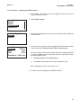
2. When the analyzer is powered up for the first time, Quick Start screens appear. Using Quick Start is easy.
a. A backlit field shows the position of the cursor.
b. To move the cursor left or right, use the keys to the left or right of the ENTER key. To scroll up or down or to increase
or decrease the value of a digit, use the keys above and below the ENTER key. Use the left and right keys to move
the decimal point.
c. Press ENTER to store a setting. Press EXIT to leave without storing changes. Pressing EXIT also returns the
display to the initial Quick Start screen.
d. A vertical black bar with a downward pointing arrow on the right side of the screen means there are more items to
display. Continue scrolling down to display all the items. When you reach the bottom of the list, the arrow will point up.
Language
English
Francais
Espanol
Deutsch
3. Choose the desired language. Scroll down to display more choices.
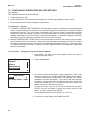
S1 Measurement
Free Chlorine
pH Independ. Free Cl
Total Chlorine
Monochloramine
4. Choose total chlorine for sensor 1 (S1).
Units
ppm
mg/L
16
5. Choose the desired units for chlorine.
MODEL TCL
Temp Units
SECTION 4
WIRING
6. Choose the desired temperature units.
o
C
F
o
7. The main display appears. The outputs and alarms (if an alarm board is present) are assigned to default values.
8. To change outputs, alarms, and other settings go to the main menu and choose Program. Follow the prompts. A
menu tree is on the following page. To calibrate the sensor refer to section 9.
17
MENU TREE
Calibrate
Sensor 1 (Total chlorine)
Chlorine
Zero
In process
Temperature
Output 1
Output 2
Hold
Sensor 1
Sensor 2
Display
Main format configuration
Language selection
Warning (enable or disable)
Screen contrast
Program
Outputs
Range (assign values to 4 and 20 mA)
Configure
Output 1 or 2
Assign sensor and measurement
Range
Scale
Dampening
Fault mode (fixed or live)
Fault value (output current)
Simulate
Alarms
Configure/Setpoint
Alarm 1, 2, 3, or 4
Setpoint
Assign sensor and measurement
High or low logic
Deadband
Interval time
On time
Recovery time
Simulate
Synchronize timers
Measurement
Total chlorine (sensor 1)
Measurement selection
Units
Filter
Resolution
Temperature
Units
Temperature compensation (auto or manual)
Set manual temperature (if selected)
Security
Calibrate/Hold only
All
Reset Analyzer
18
MODEL TCL
SECTION 5
START-UP
SECTION 5. START-UP
NOTE
Complete Section 4 before starting this section.
5.1 PREPARE THE REAGENT
WARNING
The reagent contains potassium iodide dissolved in distilled vinegar or 5%
acetic acid. Avoid contact with skin and eyes. Wash thoroughly after using.
1. DO NOT PREPARE THE SOLUTION UNTIL READY TO USE.
2. Position the blue plastic carboy under the sample conditioning cabinet. Unscrew the cap and reagent tube
assembly.
3. Add the potassium iodide reagent to the carboy. See the table.
Expected range,
ppm as Cl2
Amount of KI needed
per 5 gal (19 L) of vinegar
Part number
0 – 5 ppm
25 grams
24164-00
0 – 10 ppm
50 grams
24164-01
0 – 20 ppm
2 x 50 grams
24164-01
4. Add five gallons (19 L) of distilled white vinegar one gallon (4 L) at a time. Swirl the carboy after each addition
5. Screw the cap on the carboy. Be sure the reagent uptake tube extends to the bottom of the carboy.
6. If it hasn’t already been connected, connect the reagent tube to the small fitting on the bottom left hand side
of the enclosure.
NOTE
The shelf life of the potassium iodide vinegar solution is at least two months if stored in the blue
carboy. Do not store the reagent in a container other than the blue carboy. The reagent is sensitive to sunlight, which the blue carboy effectively blocks.
5.2 ZERO THE SENSOR
1. Place the sensor in a beaker of deionized water or simply place the sensor in air.
2. Let the sensor operate until the sensor current is stable, then zero the sensor. See Section 9.3.2 for detailed
instructions.
5.3 START SAMPLE FLOW
Adjust the sample flow until a slow stream of liquid is running down the inside tube of the sampling cup.
5.4 BEGIN OPERATION AND CALIBRATE THE SENSOR
1. Turn on the reagent and sample pump switches. Observe that liquid begins to fill the flow cell. The sample flow
is about 11 mL/min, so the flow cell will fill rather slowly. Also observe that the air pump is operating. The pump
will produce very vigorous bubbling in the flow cell.
2. Once the flow of reagent starts, it takes about two minutes for the reagent to reach the flow cell. If the concentration of total chlorine in the sample is greater than about 0.5 ppm, the treated sample in the flow cell will
be pale yellow. Sample containing more chlorine will be dark yellow.
3. Monitor the sensor current. Once the reading is stable, calibrate the unit. See Section 9.3.3 for detailed instructions. It may take thirty minutes or longer for the reading to stabilize when the sensor is first put in service.
19
MODEL TCL
SECTION 6
START-UP
SECTION 6. DISPLAY AND OPERATION
6.1. DISPLAY
The analyzer has a six line display. See Figure 6-1.
The display can be customized to meet user requirements. Refer to section 6.6.
FIGURE 6-1. Main Display
When the analyzer is being programmed or calibrated,
the display changes to a screen similar to the one
shown in Figure 6-2. The live readings appear in
small font at the top of the screen. The rest of the display shows programming and calibration information.
Programming items appear in lists. The screen can
show only four items at a time, and the arrow bar at the
right of the screen indicates whether there are additional items in the list. See Figure 6.3 for an explanation of the arrow bar.
FIGURE 6-2. Programming Screen Showing
Item List. The position of the cursor is shown in
reverse video. See Section 4.2 and 4.3 for more
information.
FIGURE 6-3. Arrow Bar. The arrow bar shows whether
additional items in a list are available.
20
MODEL TCL
SECTION 6
START-UP
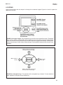
6.2 KEYPAD
Local communication with the analyzer is through the membrane keypad. Figures 6-4 and 6-5 explain the
operation of the keys.
FIGURE 6-4. Analyzer keypad. Four navigation keys move the cursor around the screen. The position
of the cursor is shown in reverse video. The navigation keys are also used to increase or decrease the
value of a numeral. Pressing ENTER selects an item and stores numbers and settings. Pressing EXIT
returns to the previous screen without storing changes. Pressing MENU always causes the main menu
to appear. .
Moves cursor up or increases
the value of the selected digit.
Moves cursor to
the left.
Moves cursor
to the right.
Moves cursor down or decreases
the value of the selected digit.
FIGURE 6-5. Navigation keys. The operation of the navigation keys is shown. To move a decimal
point, highlight it, then press the up or down key
21
MODEL TCL
SECTION 6
START-UP
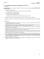
6.3 PROGRAMMING THE ANALYZER—TUTORIAL
Setting up and calibrating the analyzer is easy. The following tutorial describes how to move around in the
programming menus. For practice, the tutorial also describes how to assign ppm chlorine values to the 4 and 20 mA
analog outputs.
Menu
Calibrate
Hold
Program
Display
1. Press MENU. The main menu screen appears. There are four items in the
main menu. Calibrate is in reverse video, meaning that the cursor is on
Calibrate.
2. To assign values to the analog outputs, the Program sub-menu must be
open. Use the down navigation key to move the cursor to Program.
Press ENTER.
Program
Outputs
Alarms
Measurement
Temperature
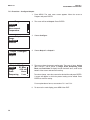
3. The Program menu appears. There are between five and seven items in
the Program menu. Alarms appears only if the analyzer contains the
optional alarm relay board. The screen displays four items at a time. The
downward pointing arrow on the right of the screen shows there are more
items available in the menu. To view the other items, use the down key to
scroll to the last item shown and continue scrolling down. When you have
reached the bottom, the arrow will point up. Move the cursor back to
Outputs and press ENTER.
Outputs
4. The screen at left appears. The cursor is on Range. Output Range is
used to assign values to the low and high current outputs. Press ENTER.
Range
Configure
Stimulate
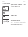
Output Range
O1 S1 4mA 0.000 ppm
O1 S1 20mA: 10.00 ppm
O2 S1 4mA:
0.0C
O2 S1 20mA:
100.0C
O1 S1 20 mA
1 0.00 ppm
5. The screen at left appears. The screen shows the present values
assigned to output 1 (O1) and output 2 (O2). The screen also shows
which sensors the outputs are assigned to. S1 is sensor 1 and S2 is
sensor 2. S2 appears only if you have a dual input 1056 analyzer. The
assignments shown are the defaults for a single channel chlorine analyzer.
Outputs are freely assignable under the configure menu.
6. For practice, change the 20 mA setting for output 1 to 8.5 ppm.
a. Move the cursor to the O1 S1 20 mA: 10.00 line and press ENTER.
b. The screen at left appears.
c.
Use the navigation keys to change 10.00 to 8.5 ppm. Use the left and
right keys to move from digit to digit. Use the up and down keys to
increase or decrease the numeral.
d. To move the decimal point, press the left or right navigation key until
the decimal point is highlighted. Press the up key to move the decimal
point to the right. Press the down key to move to the left.
e. Press ENTER to store the setting.
22
MODEL TCL
Output Range
O1 S1 4mA: 0.000 ppm
O1 S1 20mA: 08.50 ppm
O2 S1 4mA:
0.0C
O2 S1 20mA:
100.0C
SECTION 6
START-UP
7. The display returns to the summary screen at left. Note that the 20 mA
setting for output1 has changed to 8.5 ppm.
8. To return to the main menu, press MENU. To return to the main display,
press MENU then EXIT.
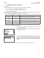
6.4 SECURITY
6.4.1 How the Security Code Works
Security codes prevent accidental or unwanted changes to program settings or calibrations. There are three
levels of security.
a. A user can view the default display and diagnostic screens only.
b. A user has access to the calibration and hold menus only.
c. A user has access to all menus.
Security Code
0 00
1. If a security code has been programmed, pressing MENU causes the
security screen to appear.
2. Enter the three-digit security code.
3. If the entry is correct, the main MENU screen appears. The user has
access to the sub-menus the code entitles him to.
4. If the entry is wrong, the invalid code screen appears.
6.4.2 Assigning Security Codes.
See Section 7.7.
6.4.3 Bypassing Security Codes
Call the factory.
23
MODEL TCL
SECTION 6
START-UP
6.5 USING HOLD
6.5.1 Purpose
To prevent unwanted alarms and improper operation of control systems or dosing pumps, place the alarms and
outputs assigned to the sensor in hold before removing it for maintenance. During hold, outputs assigned to the
sensor remain at the last value, and alarms assigned to the sensor remain in their present state.
Once in hold, the sensor remains in hold until hold is turned off. However, if power is lost then restored, hold will
automatically be turned off.
6.5.2 Using the Hold Function.
1. Press MENU. The main menu screen appears. Move the cursor to
Program.
2. Choose HOLD.
Menu
Calibrate
Hold
Program
Display
Hold
S1 Hold
Hold
S1
S2 Hold
S1 Hold outputs
and alarms?
No
Yes
No
24
No
No
3. The screen shows the current hold status for each sensor. Select the
sensor to be put in hold. Press ENTER.
4. To put the sensor in hold, choose Yes. To take the sensor out of hold,
choose No.
Once in hold, the sensor remains in hold until hold is turned off.
However, if power is lost then restored, hold will automatically be turned
off.
MODEL TCL
SECTION 6
START-UP
6.6 CONFIGURING THE MAIN DISPLAY
The main display can be configured to meet user requirements.
1. Press MENU. The main menu screen appears. Move the cursor to
Display and press ENTER.
Display
Main Format
Language:
English
Warning:
Enable
Contrast
2. The screen shows the present configuration. There are four items: Main
Format, Language, Warning, and Contrast.
To make a change, move the cursor to the desired line and press ENTER.
A screen appears in which the present setting can be edited. Press
ENTER to store the setting.
3. Main Format lets you configure the second line in the main display as
well as the four smaller items at the bottom of the display. Move the cursor to the desired place in the screen and press ENTER. Scroll through
the list of items and select the parameter you wish displayed. Once you
are done making changes, press EXIT twice to return to the display menu.
Press MENU then EXIT to return to the main display.
The following abbreviations are used in the quadrant display.
O
T
Tm
M
I
output
temperature (live)
temperature (manual)
measurement
sensor current (Cl)
If you have a dual input 1056 analyzer, other abbreviations might appear.
Consult the 1056 instruction manual for more details.
4. Choose Language to change the language used in the display.
5. Choose Warning to disable or enable warning messages.
6. Choose Contrast to change the display contrast. To change the contrast,
choose either lighter or darker and press ENTER. Every time you press
ENTER the display will become lighter or darker.
25
MODEL TCL
SECTION 7
PROGRAMMING THE ANALYZER
SECTION 7. PROGRAMMING THE ANALYZER
7.1 GENERAL
This section describes how to make the following program settings using the local keypad.
a. Configure and assign values to the analog current outputs.
b. Configure and assign values to the alarm relays (if the alarm board is installed).
c. Choose the type of chlorine measurement being made. This step is necessary because the analyzer used with
the TCL can measure forms of chlorine other than total chlorine.
d. Choose temperature units and automatic or manual temperature correction.
e. Set two levels of security codes.
f. Reset the analyzer to factory default settings.
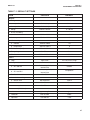
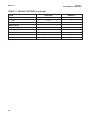
7.2 DEFAULT SETTINGS
The analyzer leaves the factory with the default settings for total chlorine shown in Table 7.1. The setting can be
changed by the user to any value shown in the column labeled CHOICES. If you have a dual input 1056 analyzer,
refer to the 1056 instruction manual for information about the default settings for second input.
26
MODEL TCL
SECTION 7
PROGRAMMING THE ANALYZER
TABLE 7-1. DEFAULT SETTINGS
ITEM
CHOICES
DEFAULT
a. output 1
chlorine, temp
chlorine
b. output 2
chlorine, temp
temp
0-20 or 4-20 mA
4 – 20 mA
a. chlorine
-9999 to +9999
0
b. temperature
-999.9 to +999.9
0
a. chlorine
-9999 to +9999
10
b. temperature
-999.9 to +999.9
0
5. Fault current (fixed)
0.00 to 22.00 mA
22.00 mA
0 to 999 sec
0 sec
0.00 to 22.00 mA
12.00 mA
high or low
AL1 low, AL2,3,4 high
a. AL1 and AL2
chlorine, temp, fault,
interval timer
chlorine
b. AL3 and AL4
chlorine, temp, fault,
interval timer
temperature
0 to 9999
0
0.0 to 999.9 hr
24.0 hr
b. on time
0 to 999 sec
10 sec
c. recovery time
0 to 999 sec
60 sec
1. units
ppm or mg/L
ppm
2. resolution
0.01 or 0.001
0.001
3. input filter
0 to 999 sec
5 sec
Outputs
1. Assignments
2. Range
3. 0 or 4 mA setting
4. 20 mA setting
6. Dampening
7. Simulate
Alarms
1. Logic
2. Assignments
3. Deadband
4. Interval timer settings
a. interval time
Measurement (Chlorine)
27
MODEL TCL
SECTION 7
PROGRAMMING THE ANALYZER
TABLE 7-1. DEFAULT SETTINGS (continued)
ITEM
CHOICES
DEFAULT
ºC or ºF
ºC
automatic or manual
automatic
1. Calibrate/Hold
000 to 999
000
2. Program/Display
000 to 999
000
1. 4 mA
0.000 to 22.000 mA
4.000 mA
2. 20 mA
0.000 to 22.000 mA
20.000 mA
Temperature related settings
1. Units
2. Temperature compensation
Security Code
Calibration–Analog Outputs
28
MODEL TCL
SECTION 7
PROGRAMMING THE ANALYZER
7.3 CONFIGURING, RANGING, AND SIMULATING OUTPUTS.
7.3.1 Purpose
This section describes how to configure, range, and simulate the two analog current outputs. CONFIGURE THE
OUTPUTS FIRST.
1. Configuring an output means…
a. Assigning a sensor and measurement (chlorine or temperature) to an output.
b. Selecting a 4-20 mA or 0-20 mA output.
c. Choosing a linear or logarithmic output.
d. Turning output current dampening on or off.
e. Selecting the value the output current goes to if the analyzer detects a fault.
2.
Ranging the outputs means assigning values to the low (0 or 4 mA) and high (20 mA) outputs.
3. Simulating an output means making the analyzer generate an output current equal to the value entered by the
user.
7.3.2 Definitions
1.
2.
3.
4.
5.
6.
7.
ANALOG CURRENT OUTPUT. The analyzer provides either a continuous 4-20 mA or 0-20 mA output
signal proportional to chlorine or temperature.
ASSIGNING AN OUTPUT. Outputs can be assigned to either the measurement (total chlorine) or temperature.
If a dual input analyzer is being used, the outputs are freely assignable to either sensor.
LINEAR OUTPUT. Linear output means the current is directly proportional to the value of the variable assigned
to the output (chlorine or temperature).
LOGARITHMIC OUTPUT. Logarithmic output means the current is directly proportional to the common
logarithm of the variable assigned to the output (chlorine or temperature).
DAMPENING. Output dampening smoothes out noisy readings. It also increases response time. The time
selected for output dampening is the time to reach 63% of the final reading following a step change. Output
dampening does not affect the response time of the display.
FAULT. The analyzer continuously monitors itself and the sensor(s) for faults. If the analyzer detects a fault, a
fault message appears in the main display. At the same time the output current goes to the value programmed
in this section. There are two output fault modes: fixed and live. Fixed means the selected output goes the
previously programmed value (between 0.00 and 22.00 mA) when a fault occurs. Live means the selected
output is unaffected when a fault occurs.
RANGING AN OUTPUT. The outputs are fully rangeable, including negative numbers. If the output is
logarithmic, assigned values must be positive.
29
MODEL TCL
SECTION 7
PROGRAMMING THE ANALYZER
7.3.3. Procedure – Configure Outputs.
1. Press MENU. The main menu screen appears. Move the cursor to
Program and press ENTER.
Program
Outputs
Alarms
Measurement
Temperature
Outputs
2. The cursor will be on Outputs. Press ENTER.
3. Choose Configure.
Range
Configure
Simulate
Output 1 Configure
Program
Output 1
Output 2
Output 1 Configure
S1 Meas
Assign:
Range:
4-20 mA
Scale:
Linear
Dampening
0 sec
4. Choose Output 1 or Output 2.
5. The screen shows the present configuration. There are six items: Assign
(S1 is sensor 1, S2 is sensor 2), Range, Scale, Dampening, Fault
Mode, and Fault Value To display the fifth and sixth items, scroll to the
bottom of the screen and continue scrolling.
To make a change, move the cursor to the desired line and press ENTER.
A screen will appear in which the present setting can be edited. Press
ENTER to store the setting.
For an explanation of terms, see sections 7.3.1 and 7.3.2.
6. To return to the main display, press MENU then EXIT.
30
MODEL TCL
SECTION 7
PROGRAMMING THE ANALYZER
7.3.3. Procedure – Ranging Outputs.
1. Press MENU. The main menu screen appears. Move the cursor to
Program and press ENTER.
Program
Outputs
Alarms
Measurement
Temperature
Outputs
2. The cursor will be on Outputs. Press ENTER.
3. Choose Range.
Range
Configure
Simulate
Output Configure
Program
Output 1
Output 2
Output Range
O1 S1 4mA 0.000 ppm
O1 S1 20mA: 10.00 ppm
O2 S1 4mA:
0.0C
O2 S1 20mA:
100.0C
4. Choose Output 1 or Output 2.
5. The screen shows the present settings for the outputs. O1 is output 1, O2
is output 2, S1 is sensor 1, and S2 is sensor 2.
To make a change, move the cursor to the desired line and press ENTER.
A screen will appear in which the present setting can be edited. Press
ENTER to store the setting.
For an explanation of terms, see sections 7.3.1 and 7.3.2.
6. To return to the main display, press MENU then EXIT.
31
MODEL TCL
SECTION 7
PROGRAMMING THE ANALYZER
7.3.4 Procedure – Simulating Outputs
1. Press MENU. The main menu screen appears. Move the cursor to
Program and press ENTER.
Program
Outputs
Alarms
Measurement
Temperature
2. The cursor will be on Outputs. Press ENTER.
Outputs
Range
Simulate
Configure
Simulate
3. Choose Simulate.
Simulate
Program
Output 1
Output 2
4. Choose Output 1 or Output 2.
Output 1 Hold at
1 2.00 mA
5. Enter the desired simulated output current. To end the simulated current,
press MENU or EXIT.
7.4 CONFIGURING ALARMS AND ASSIGNING SETPOINTS.
7.4.1 Purpose
The Model 1056 analyzer has an optional alarm relay board. This section describes how to configure and assign
setpoints to the alarm relays, simulate alarm action, and synchronize interval timers. CONFIGURE THE ALARMS
FIRST.
1. Configuring an alarm means…
a. Assigning a measurement (chlorine or temperature) to an alarm. If a dual input analyzer is being used,
the alarms are freely assignable to either sensor. An alarm relay can also be used as a timer.
b. Selecting high or low logic.
c. Choosing a deadband.
d. Setting the interval timer parameters.
2. Simulating an alarm means making the analyzer energize or de-energize an alarm relay.
32
MODEL TCL
SECTION 7
PROGRAMMING THE ANALYZER
7.4.2 Definitions
1. ASSIGNING ALARMS. There are four alarms
relays. The relays are freely assignable to any
sensor and to either the measurement (chlorine)
or temperature. Alarm relays can also be assigned
to operate as interval timers or as fault alarms. A
fault alarm activates when the analyzer detects a
fault in either itself or the sensor.
2. FAULT ALARM. A fault condition exits when the
analyzer detects a problem with a sensor or with
the analyzer itself that is likely to cause seriously
erroneous readings. If an alarm was programmed
as a fault alarm, the relay will activate. At the
same time a fault message will appear in the main
display.
3. ALARM LOGIC, SETPOINTS, AND DEADBANDS. See Figures 7-1 and 7-2.
FIGURE 7-1. High alarm logic. The alarm activates
when the chlorine concentration exceeds the high setpoint. The alarm remains activated until the reading
drops below the value determined by the deadband.
4. INTERVAL TIMER. Any alarm relay can be used
as an interval timer. Figure 7-3 shows how the
timer operates. While the interval timer is operating, the main display, analog output, and alarms
for the sensor(s) can be put on hold. During hold,
the main display remains at the last value.
5. SYNCHRONIZE TIMER. If two or more relays are
being used as interval timers, choosing synchronize timers will cause each timer to start one
minute later than the preceding timer.
FIGURE 7-2. Low alarm logic. The alarm activates
when the chlorine concentration drops below the low setpoint. The alarm remains activated until the reading
increases above the value determined by the deadband.
FIGURE 7-3. Operation of the interval timer. The numbers in parentheses are the allowed values for each
timer parameter.
33
MODEL TCL
SECTION 7
PROGRAMMING THE ANALYZER
7.4.3 Procedure – Configuring Alarms and Assigning Setpoints
1. Press MENU. The main menu screen appears. Move the cursor to
Program and press ENTER.
Program
Outputs
Alarms
Measurement
Temperature
2. Choose Alarms.
Alarms
Configure/Setpoint
Simulate
Synch Timers:
Yes
3. Choose Configure/Setpoint.
Configure/Setpoint
Alarm 1
Alarm 2
Alarm 3
Alarm 4
4. Choose Alarm 1, Alarm 2, Alarm 3, or Alarm 4.
Alarm 1 Settings
Setpoint: 0.000 ppm
Assign: S1 Measure
Logic:
Low
Deadband: 0.000 ppm
5. The screen summarizes the present configuration and setpoints. There
are nine items: Setpoint, Assign (S1 is sensor 1 and S2 is sensor 2),
Logic, Deadband, Interval time, On time, Recover time, and Hold
while active. The last four items describe the operation of the timer. Only
four items are shown at a time. To view the remaining items, scroll to the
bottom of the screen and continue scrolling.
To make a change, move the cursor to the desired line and press ENTER.
A screen will appear in which the present setting can be edited. Press
ENTER to store the setting.
For an explanation of terms, see sections 7.4.1 and 7.4.2.
6. To return to the main display, press MENU then EXIT.
34
MODEL TCL
SECTION 7
PROGRAMMING THE ANALYZER
7.4.4 Procedure – Simulating Alarms
1. Press MENU. The main menu screen appears. Move the cursor to
Program and press ENTER.
Program
Outputs
Alarms
Measurement
Temperature
2. Choose Alarms.
Alarms
Configure/Setpoint
Simulate
Synch Timers:
Yes
3. Choose Simulate.
Simulate
Alarm 1
Alarm 2
Alarm 3
Alarm 4
4. Choose Alarm 1, Alarm 2, Alarm 3, or Alarm 4.
Simulate Alarm 1
Don’t Simulate
De-energize
Energize
5. Choose Don’t simulate, De-energize, or Energize. Press MENU or
EXIT to end simulation.
35
MODEL TCL
SECTION 7
PROGRAMMING THE ANALYZER
7.4.5 Procedure – Synchronizing Timers
1. Synch Timers is available only if two or more alarm relays have been configured as interval timers.
2. Press MENU. The main menu screen appears. Move the cursor to
Program and press ENTER.
Program
Outputs
Alarms
Measurement
Temperature
3. Choose Alarms.
Alarms
Configure/Setpoint
Simulate
Synch Timers:
Yes
4. The summary display shows the current Synch Timers setting, (Yes or
No)
To make a change, choose Synch Timers and press ENTER. A screen
will appear in which the present setting can be edited. Press ENTER to
store the setting.
For an explanation of terms, see sections 7.4.1 and 7.4.2.
5. To return to the main display, press MENU then EXIT.
7.5 CONFIGURING THE MEASUREMENT.
7.5.1 Purpose
This section describes how to do the following:
1. Program the analyzer to measure total chlorine. This step is necessary because the analyzer can be used
with other sensors to measure other chlorine oxidants.
2. Set the level of electronic filtering of the sensor current.
3. Set the display resolution.
7.5.2 Definitions
1. CHLORINE OXIDANTS. Although the TCL is used to measure total chlorine only, the 1056 analyzer used with
the TCL can be used to measure other chlorine oxidants, for example monochloramine and free chlorine.
2. FILTER. The analyzer applies a filter to the raw sensor current. The filter reduces noise but increases the
response time. The available filter(s) depend on the time setting. If the filter is between 0 and 10 seconds, the
analyzer applies a window filter. A window filter averages the measured value within the filter time. For example, if the filter is 5 seconds and a step increase is applied to the input, the displayed value increases linearly,
reaching the final value after 5 seconds. If the filter is set to greater than 10 seconds, the analyzer applies
either an adaptive filter or a continuous filter. An adaptive filter discriminates between noise and real process
change. It filters changes below a fixed threshold value but does not filter changes that exceed the threshold.
It is best used in situations where the noise is relatively low. A continuous filter dampens all changes. The filter time setting is approximately equal to the time constant, the amount of time required for the reading to reach
63% of the final value following a step change.
3. RESOLUTION. If the chlorine concentration is less than 1.00 ppm (mg/L), the display resolution can be set to
0.XX or 0.XXX.
36
MODEL TCL
SECTION 7
PROGRAMMING THE ANALYZER
7.5.3 Procedure – Configuring the Measurement
1. Press MENU. The main menu screen appears. Move the cursor to
Program and press ENTER.
Program
Outputs
Alarms
Measurement
Temperature
2. Choose Measurement.
Configure?
Sensor1
Sensor 1
Sensor 2
3. The screen at left appears only if you have a dual input 1056. Choose the
Chlorine sensor.
S1 Configure
Measure
Total Cl
Measure:
Units:
ppm
Filter:
5 sec
Resolution: 0.001 ppm
4. The screen summarizes the present configuration for the chlorine sensor.
There are four items: Measure, Units, Filter, and Resolution
To make a change, move the cursor to the desired line and press ENTER.
A screen will appear in which the present setting can be edited. To store
the setting press ENTER.
a.
For Measurement choose Total Chlorine.
b.
Leave Filter at the default value unless readings are noisy.
For an explanation of terms, see sections 7.5.2.
6. To return to the main display, press MENU then EXIT.
37
MODEL TCL
SECTION 7
PROGRAMMING THE ANALYZER
7.6 CONFIGURING TEMPERATURE RELATED SETTINGS
7.6.1 Purpose
This section describes how to do the following:
1. Choose temperature units.
2. Choose automatic or manual temperature correction for membrane permeability (chlorine sensor).
3. Enter a temperature for manual temperature compensation.
7.6.2 Definitions - Chlorine
1. AUTOMATIC TEMPERATURE CORRECTION. The total chlorine sensor is a membrane-covered amperometric
sensor. The permeability of the membrane is a function of temperature. As temperature increases, membrane
permeability increases. Thus, an increase in temperature will cause the sensor current and the analyzer
reading to increase even though the chlorine level remained constant. A correction equation in the analyzer
software automatically corrects for changes in membrane permeability. In automatic temperature correction,
the analyzer uses the temperature measured by the sensor for the correction.
2. MANUAL TEMPERATURE CORRECTION. In manual temperature correction, the analyzer uses the temperature entered by the user for correction. It does not use the actual process temperature. Do NOT use manual
temperature correction unless the measurement and calibration temperatures differ by no more than about
2ºC. Manual temperature correction is useful if the sensor temperature element has failed and a replacement
sensor is not available.
7.6.3 Procedure – Configuring Temperature Related Settings
1. Press MENU. The main menu screen appears. Move the cursor to
Program and press ENTER.
Program
Outputs
Alarms
Measurement
Temperature
Temperature
Units:
C
Units:
S1 Temp Comp: Auto
2. Choose Temperature.
3. The screen summarizes the present sensor configuration. There will be
between two and five items. Units and S1 Temp Comp, always appear.
If manual temperature compensation was selected, the manual
temperature value will also appear. If you have a dual input analyzer,
temperature compensation items will appear for the other sensor. Only
four items are shown at a time. To view the remaining items, scroll to the
bottom of the screen and continue scrolling.
To make a change, move the cursor to the desired line and press
ENTER. A screen will appear in which the present setting can be
edited. To store a setting, press ENTER.
For an explanation of terms, see sections 7.6.1 and 7.6.2.
4. To return to the main display, press MENU then EXIT.
38
MODEL TCL
7.7
SECTION 7
PROGRAMMING THE ANALYZER
CONFIGURING SECURITY SETTINGS
7.7.1 Purpose
This section describes how to set security codes. There are three levels of security.
a. A user can view the default display and diagnostic screens only.
b. A user has access to the calibration and hold menus only.
c. A user has access to all menus.
The security code is a three digit number. The table shows what happens when different security codes (XXX and
YYY) are assigned to Calibration/Hold and All. 000 means no security.
Calibration/Hold
All
000
XXX
User enters XXX and has access to all menus.
XXX
YYY
User enters XXX and has access to Calibration and Hold
menus only. User enters YYY and has access to all menus.
XXX
000
User needs no security code to have access to all menus.
000
000
User needs no security code to have access to all menus.
What happens…
7.7.2 Procedure – Configuring Security Settings
1. Press MENU. The main menu screen appears. Move the cursor to
Program and press ENTER.
2. Scroll to the bottom of the screen and continue scrolling unit Security is
highlighted. Press ENTER.
Program
Alarms
Measurement
Temperature
Security
Security
Calibration/Hold
Calibration/Hold
All
000
000
3. The screen shows the existing security codes. To make a change, move
the cursor to the desired line and press ENTER. A screen will appear in
which the present setting can be edited. Press ENTER to store the
change. The security code takes effect two minutes after pressing
ENTER.
4. To return to the main display, press MENU then EXIT.
39
MODEL TCL
7.8
SECTION 7
PROGRAMMING THE ANALYZER
RESETTING THE ANALYZER
7.8.1 Purpose
This section describes how to clear user-entered values and restore default settings. There are three resets:
1. Resetting to factory default values clears ALL user entered settings, including sensor and analog output
calibration, and returns ALL settings and calibration values to the factory defaults.
2. Resetting a sensor calibration to the default values clears user-entered calibration data for the selected
sensor but leaves all other user-entered data unaffected.
3. Resetting the analog output calibration clears only the user-entered analog output calibration. It leaves all
other user-entered settings unchanged.
7.8.2 Procedure – Resetting the Analyzer
1. Press MENU. The main menu screen appears. Move the cursor to
Program and press ENTER.
Program
Temperature
Security
Diagnostics
Reset Analyzer
Reset Analyzer
Factory
Factory Defaults
Defaults
Sensor Cal Only
Output Cal Only
2. Scroll to the bottom of the screen and continue scrolling until Reset
Analyzer is highlighted. Press ENTER.
3. Choose whether to reset all user-entered values (Factory Defaults),
sensor calibration (Sensor Cal Only), or output calibration (Output Cal
Only). If you choose Sensor Cal Only or Output Cal Only a second
screen appears in which you can select which sensor or output
calibration to reset.
4. To return to the main display, press MENU then EXIT.
40
MODEL TCL
SECTION 8
DIGITAL COMMUNICATIONS
SECTION 8. DIGITAL COMMUNICATIONS
For information about digital communications, refer to the following manuals:
HART
51-1056HT Model 56 HART Addendum
Profibus DP
51-1056DP Model 56 Profibus DP Addendum
41
MODEL TCL
SECTION 9
CALIBRATION
SECTION 9. CALIBRATION
9.1 INTRODUCTION
The calibrate menu allows the user to do the following:
1. Calibrate the temperature sensing element in the total chlorine sensor.
2. Calibrate the chlorine sensor.
3. Calibrate the analog outputs.
9.2 CALIBRATING TEMPERATURE
9.2.1 Purpose
The total chlorine sensor is a membrane-covered amperometric sensor. As the sensor operates, iodine, produced
by the reaction between total chlorine and the vinegar/potassium iodide reagent, diffuses through the membrane
and is consumed at an electrode immediately behind the membrane. The reaction produces a current that depends
on the rate at which iodine diffuses through the membrane. The diffusion rate, in turn, depends on the concentration of the iodine and how easily it passes through the membrane (the membrane permeability). Because
membrane permeability is a function of temperature, the sensor current will change if either the concentration
or temperature changes. To account for changes in sensor current caused by temperature alone, the analyzer
automatically applies a membrane permeability correction. The membrane permeability changes about 3%/°C at
25°C, so a 1°C error in temperature produces about a 3% error in the reading.
Without calibration the accuracy of the temperature measurement is about ±0.4°C. Calibrate the sensor/analyzer
unit if...
1. ±0.4°C accuracy is not acceptable
2. the temperature measurement is suspected of being in error. Calibrate temperature by making the analyzer
reading match the temperature measured with a standard thermometer.
42
MODEL TCL
SECTION 9
CALIBRATION
9.2.2 Procedure
1. Remove the sensor from the flow cell. Place it in an insulated container of water along with a calibrated
thermometer. Submerge at least the bottom two inches of the sensor.
2. Allow the sensor to reach thermal equilibrium. The time constant for the chlorine sensor is about 5 min., so
it may take as long as 30 min for equilibration.
3. Press MENU. The main menu screen appears. The cursor will be on
Calibrate. Press ENTER.
Calibrate
Sensor
Sensor 11
Sensor 2
Output 1
Output 2
4. Choose the sensor you wish to calibrate. Sensor 2 appears only if
you are using a dual input analyzer.
S1 Calibration
Total Chlorine
Sensor
1
Temperature
5. Choose Temperature.
S1 Calibration
+ 25.0°C
6. Change the display to match the temperature read from the calibrated
thermometer. Press ENTER.
If the present temperature is more than 5ºC different from the value
entered, an error message appears. To force the analyzer to accept
the calibration, choose Yes. To repeat the calibration, choose No. For
troubleshooting assistance, see Section 11.5.7.
7. To return to the main display, press MENU then EXIT.
43
MODEL TCL
SECTION 9
CALIBRATION
9.3 CALIBRATING TOTAL CHLORINE
9.3.1 Purpose
The continuous determination of total chlorine requires two steps. See Figure 9-1. First, the sample flows into a
conditioning system (the Model TCL) where it is treated with acetic acid (vinegar) and potassium iodide. The acid
lowers the pH, which allows total chlorine in the sample to quantitatively oxidize the iodide to iodine. The treated
sample then flows to the sensor. The sensor is a membrane-covered amperometric sensor, whose output is proportional to the concentration of iodine. Because the concentration of iodine is also proportional to the concentration of total chlorine, the analyzer can be calibrated to read total chlorine.
Figure 9-2 shows a typical calibration curve for a total chlorine sensor. Because the sensor really measures iodine,
calibrating the sensor requires exposing it to a solution containing no iodine (zero standard) and to a solution containing a known amount of iodine (full-scale standard).
The zero standard is necessary because the sensor, even when no iodine is present, generates a small current
called the residual or zero current. The analyzer compensates for the residual current by subtracting it from the
measured current before converting the result to a total chlorine value. New sensors require zeroing before being
placed in service, and sensors should be zeroed whenever the electrolyte solution is replaced. Deionized water is
a good zero standard.
Do not zero the sensor by leaving it in the
TCL flow cell and turning off reagent injection. Even though no iodine is present, the
current measured under these conditions is
not the zero current. Instead, it is the slight
response of the sensor to total chlorine in the
sample. Always use deionized water for
zeroing the sensor.
The purpose of the full-scale standard is to
establish the slope of the calibration curve.
Because stable total chlorine standards do not
exist, the sensor must be calibrated against a
test run on a grab sample of the process liquid.
Several manufacturers offer portable test kits
for this purpose. Observe the following precautions when taking and testing the grab
sample.
•
Take the grab sample from a point as close
as possible to the inlet of the TCL sample
conditioning system.
•
Total chlorine solutions are unstable. Run
the test immediately after taking the sample. Try to calibrate the sensor when the
chlorine concentration is at the upper end
of the normal operating range.
FIGURE 9-1. Determination of Total Chlorine
FIGURE 9-2. Sensor Current as a Function of Total
Chlorine Concentration
44
MODEL TCL
SECTION 9
CALIBRATION
9.3.2 Procedure — Zeroing the Sensor
1. Place the sensor in a beaker of deionized water. Be sure no air bubbles are trapped against the membrane.
2. Observe the sensor current. The current will drop rapidly at first and then gradually reach a stable zero value.
To monitor the sensor current, press the DIAG key. Move the cursor to the chlorine sensor and press ENTER.
The input current is the first line in the display. Note the units: nA is nanoamps, uA is microamps. Typical zero
current for a 499ACL-02 sensor is -10 to +50 nA.
A new sensor or a sensor in which the electrolyte solution has been replaced may require several hours
(occasionally as long as overnight) to reach a minimum zero current. DO NOT START THE ZERO ROUTINE
UNTIL THE SENSOR HAS BEEN IN THE ZERO SOLUTION FOR AT LEAST TWO HOURS.
3. Press MENU. The main menu screen appears. The cursor will be on Calibrate. Press ENTER.
Calibrate
Sensor11
Sensor
Sensor 2
Output 1
Output 2
S1 Calibration
Total Chlorine
Temperature
S1 Calibration
ZeroCal
Cal
Zero
In Process Cal
S1 Zero Cal
Sensor zero done
S1 Possible
Error, Proceed?
No
No
Yes
4. Choose the sensor you wish to calibrate. Sensor 2 appears only if you
have a dual input 1056 analyzer.
5. Choose Total Chlorine.
6. Choose Zero Cal. The analyzer will automatically start the zero calibration
7. If the zero calibration was successful, the screen at left appears.
If the zero current is moderately larger than expected, an error message
appears. To force the analyzer to accept the zero current, choose Yes. To
repeat the calibration, choose No. For troubleshooting assistance, see
Section 11.5.
45
MODEL TCL
S1 Zero Cal
Sensor zero failed
SECTION 9
CALIBRATION
If the zero current is much larger than expected, the zero calibration
failure screen appears. The analyzer will not update the zero current. For
troubleshooting assistance, see Section 11.5.
Press Exit
8. To return to the main display, press MENU then EXIT.
9.3.3 Procedure — Calibrating the sensor
1. If the sensor was just zeroed, place the sensor back in the flow cell. Confirm that excess sample is flowing down
the inside tube of the overflow sampler. Also, verify that reagent is being delivered to the sample and that the air
pump is working.
2. Adjust the chlorine concentration until it is near the upper end of the control range. Wait until the analyzer reading
is stable before starting the calibration. When the TCL is first started up or when a new sensor is put in service,
allow at least 30 minutes for the reading to stabilize.
3. Press MENU. The main menu screen appears. The cursor will be on
Calibrate. Press ENTER.
Calibrate?
Sensor 1
Sensor 2
Output 1
Output 2
4. Choose the sensor you wish to calibrate. Sensor 2 appears only if
you have a dual input 1056 analyzer.
S1 Calibration
Total Chlorine
Temperature
5. Choose Total Chlorine.
S1 Calibration
ZeroCal
Cal
Zero
In Process Cal
6. Choose In Process Cal
46
MODEL TCL
SECTION 9
CALIBRATION
7. Follow the screen prompts: Once the reading is stable, press ENTER.
Take the sample and press ENTER. At this point, the analyzer will store
the present sensor current and temperature and use those values in the
calibration.
S1 Enter Value
1 0.00 ppm
Determine the total chlorine concentration in the sample and enter
the value in the screen shown at left. See Section 9.3.1 for sampling and
testing precautions.
8. If the calibration is successful, the live reading will change to the value
entered in step 7 and the display will return to the screen in step 6.
S1 InProcess Cal
Calibration Error
If the sensitivity is too far outside the range of expected values, the
calibration error screen shown at left will appear. The analyzer will not
update the calibration. For troubleshooting assistance, see Section 11.5.
Press Exit
9. To return to the main display, press MENU then EXIT.
9.4 CALIBRATING ANALOG OUTPUTS
9.4.1 Purpose
Although the analyzer analog outputs are calibrated at the factory, they can be trimmed in the field to match the
reading from a standard milliammeter. Both the low (0 or 4 mA) and high (20 mA) outputs can be trimmed.
9.4.2 Procedure
1. Connect a calibrated milliammeter across the output you wish to calibrate. If a load is already connected to the
output, disconnect the load. Do not put the milliameter in parallel with the load.
2. Press MENU. The main menu screen appears. The cursor will be on
Calibrate. Press ENTER.
Calibrate?
Sensor 1
Sensor 2
Output 1
Output 2
3. Choose the output you wish to calibrate.
4 mA Output 1
Cal Meter:
0 4.000 mA
4. The analyzer will simulate the low output current. Change the value in the
display to match the reading from the milliammeter.
20 mA Output 1
Cal Meter:
2 0.000 mA
5. The analyzer will simulate the 20 mA output current. Change the value in
the display to match the reading from the milliammeter.
47
MODEL TCL
Output 1
Trim Complete
SECTION 9
CALIBRATION
6. If the calibration was successful, the screen at left will appear.
7. If the user entered value is more that ±1 mA different from the nominal
value, a possible error screen will appear. To force the analyzer to accept
the calibration, choose Yes.
8. To return to the main display, press MENU then EXIT.
48
MODEL TCL
SECTION 10
MAINTENANCE
SECTION 10. MAINTENANCE
10.1 ANALYZER
The Model 1056 analyzer used with the TCL needs little routine maintenance.
Clean the analyzer case and front panel by wiping with a clean soft cloth dampened with water ONLY. Do not use
solvents, like alcohol, that might cause a buildup of static charge.
The chlorine sensor circuit board (PN 24203-01) is replaceable. If you have a dual input Model 1056 analyzer, consult the Model 1056 instruction manual for the part number of the other board.
To replace the board
1.
Turn off power to the analyzer.
2.
Loosen the four screws holding the front panel in place and let the front panel drop down.
3.
Loosen the gland fitting and carefully push the sensor cable up through the fitting as you pull out the circuit
board.
4.
Once you have access to the terminal strip, disconnect the sensor.
5.
Unplug the sensor board from the main board. See Figure 10.1.
6.
Slide the replacement board partially into the board slot. Plug the sensor board into the main board and reattach
the sensor wires.
7.
Carefully pull the sensor cable through the gland fitting as you push the sensor board back into the enclosure.
8.
Close the front panel.
9.
Turn on power.
SENSOR BOARD
CABLE CONNECTION
FIGURE 10-1. Sensor board connections.
49
MODEL TCL
SECTION 10
MAINTENANCE
10.2 TOTAL CHLORINE SENSOR
10.2.1 General
When used in clean water, the total chlorine sensor requires little maintenance. Generally, the sensor needs maintenance when the response becomes sluggish or noisy or when readings drift follow calibration. Maintenance
frequency is best determined by experience. If the sensor is used in potable water, expect to clean the membrane every month and replace the membrane and electrolyte solution every three months. Sensors used in dirty
water require more frequent maintenance and calibration. However, if experience shows the sensor is holding
calibration and not drifting appreciably between calibration intervals, the maintenance interval can be extended.
10.2.2 Cleaning the membrane.
Keep the membrane clean. Clean the membrane with water sprayed from a wash bottle. Use a soft tissue to
gently wipe the membrane.
10.2.3 Replacing the membrane.
1. Hold the sensor with the membrane facing up.
2. Unscrew membrane retainer. Remove the membrane assembly and O-ring. See Figure 10-2.
3. Inspect the cathode. If it is tarnished, clean it by gently rubbing in the direction of the existing scratches (do
not use a circular motion) with 400-600 grit silicon carbide finishing paper. Rinse the cathode thoroughly with
water.
4. Prepare a new membrane. Hold the membrane assembly with the cup formed by the membrane and membrane holder pointing up. Fill the cup with electrolyte solution. Set aside.
5. Put a new O-ring in the groove.
6
Place a drop of electrolyte solution on the cathode. Invert the membrane assembly and place it over the cathode stem.
7. Screw the membrane retainer back in place.
8. Hold the sensor with the membrane pointing down. Shake the sensor a few times, as though shaking down a
clinical thermometer.
10.2.4 Replacing the membrane and electrolyte solution.
CAUTION
Fill solution may cause irritation.
Avoid contact with skin and eyes.
May be harmful if swallowed.
1. Unscrew the membrane retainer and remove the membrane assembly and O-ring. See Figure 10-2.
2. Hold the sensor over a container with the cathode pointing down.
3. Remove the fill plug and allow the electrolyte solution to drain out.
4. Wrap the plug with two turns of pipe tape and set aside. Remove old tape first.
5. Prepare a new membrane. Hold the membrane assembly with the cup formed by the membrane and membrane holder pointing up. Fill the cup with electrolyte solution. Set aside.
6. Hold the sensor at about a 45-degree angle with the cathode end pointing up. Add electrolyte solution
(PN 9210438) through the fill hole until the liquid overflows. Tap the sensor near the threads to release trapped
air bubbles. Add more electrolyte solution if necessary.
7. Place the fill plug in the electrolyte port and begin screwing it in. After several threads have engaged, rotate
the sensor so that the cathode is pointing up and continue tightening the fill plug. Do not overtighten.
8. Place a new O-ring in the groove around the cathode post. Cover the holes at the base of the cathode stem
with several drops of electrolyte solution.
9. Insert a small blunt probe, like a toothpick with the end cut off, through the pressure equalizing port. See Figure
10-2.
50
MODEL TCL
SECTION 10
MAINTENANCE
NOTE
Do not use a sharp probe. It will puncture the bladder and destroy the sensor.
Gently press the probe against the bladder several times to force liquid through the holes at the base of the
cathode stem. Keep pressing the bladder until no air bubbles can be seen leaving the holes. Be sure the holes
remain covered with electrolyte solution.
10. Place a drop of electrolyte solution on the cathode, then place the membrane assembly over the cathode.
Screw the membrane retainer in place.
11. The sensor may require several hours operating at the polarizing voltage to equilibrate after the electrolyte
solution has been replenished.
FIGURE 10-2. Sensor Parts
TABLE 10-1. Spare Parts
33523-00
9550094
33521-00
23501-02
23502-02
9210438
Electrolyte Fill Plug
O-Ring, Viton 2-014
Membrane Retainer
Total Chlorine Membrane Assembly: includes one membrane assembly and one O-ring
Total Chlorine Membrane Kit: includes 3 membrane assemblies and 3 O-rings
Total Chlorine Sensor Fill Solution, 4 oz (120 mL)
51
MODEL TCL
SECTION 10
MAINTENANCE
10.3 SAMPLE CONDITIONING SYSTEM
10.3.1 Reagent
The sample conditioning reagent lasts about 2 months. Before putting fresh reagent in the carboy, discard any
small amount of remaining reagent. To prepare the reagent refer to the procedure in Section 5.1. See Table 10-2
for ordering information.
10.3.2 Sample and reagent tubing.
Periodically inspect sample and reagent tubing for cracks and leaks. Replace tubing if it is damaged.
After a period of time, the sample tubing may become plugged with suspended matter. The tubing is flexible and
difficult to clean mechanically. Plugged sample tubing is best replaced.
Replacement tubing kits are available. See Table 10-2 for part numbers.
To replace reagent tubing:
1. Reagent tubing is shown in Figure 10-2.
2. Turn off sample and reagent pumps.
3. Luer fittings connect the reagent tubing to the pump. Disconnect the tubing by turning the fitting in the direction of the arrows shown in Figure 10-5.
4. Disconnect the other end of the suction tubing from the barb on the reagent inlet fitting in the bottom of the
enclosure. Disconnect the other end of discharge tubing from the reagent injection tee.
5. Install the replacement tubing. Note that the discharge tubing is longer than the suction tubing.
FIGURE 10-3. Replacing Reagent Tubing
52
MODEL TCL
SECTION 10
MAINTENANCE
To replace sample tubing:
1. Sample tubing is shown in Figure 10-4.
2. Turn off the sample and reagent pumps.
3. Luer fittings connect the sample tubing to the pump. Disconnect the tubing by turning the fitting in the
direction of the arrows shown in Figure 10-5.
4. Disconnect the other end of the sample pump suction tubing from the overflow sampler. Pull the reagent
injection tube off the reagent injection tee.
5. Disconnect the other end of the sample pump discharge tubing from the flow cell. Pull the air injection tube off
the air injection tee.
6. Disconnect the sample inlet and drain tubing.
7. Install the replacement sample pump suction and discharge tubing assemblies. The assemblies look similar.
To tell the difference, note the air injection tee in the discharge tubing assembly has a larger diameter barb
than the reagent injection tee in the suction tubing assembly.
8. Install replacement sample inlet and drain tubing. The sample inlet tubing is longer than the drain tubing.
FIGURE 10-4. Replacing Sample Tubing
53
MODEL TCL
SECTION 10
MAINTENANCE
10.3.3 Peristaltic pump tubing.
The expected life of the peristaltic pump tubing is one year.
To replace pump tubing:
1. Turn off the sample and reagent pumps.
2. The reagent and sample tubing is connected to the pump tubing
with luer fittings. See Figure 10-5. Disconnect the fittings from
the pump by turning the fitting in the direction of the arrow.
FIGURE 10-5.
3. Using your thumb and forefinger gently pinch the sides of the
pump cover. Slide the cover upwards to remove it. See Figure
10-6.
FIGURE 10-6.
4. Using your thumb as shown in Figure 10-7, push the tubing fitting straight outward until the fitting slides out of the socket.
Repeat the process for the other fitting.
5. Remove and discard the pump tubing.
FIGURE 10-7.
6. Insert the new tubing one end at a time. Tongues on the sides
of the gray fittings at the ends of the tube fit into receiving
grooves in the pump casing. See Figure 10-8. Push the fitting
into place until it clicks. Gently stretch the tubing over the rollers
and insert the other fitting into the receiving socket on the other
side of the pump.
54
FIGURE 10-8.
MODEL TCL
SECTION 10
MAINTENANCE
7. Replace the pump cover.
a. Place the cover on the pump casing. See Figure 10-9.
FIGURE 10-9.
b. Be sure the pins at the bottom of the cover (Figure 10-10)
ride on the tracks in the pump casing.
FIGURE 10-10.
c.
The position of the track is outlined in Figure 10-11. The pins
on the pump cover must ride in these tracks as the cover is
pushed into place. Gently squeeze the ends of the cover to
guide the pins.
FIGURE 10-11.
d. Push down until the cover snaps into place.
8. Reconnect the tubing.
55
MODEL TCL
SECTION 10
MAINTENANCE
10.3.4 Replacing the air pump
WARNING
1. Disconnect power to the analyzer.
2. Refer to Figure 10-12. Disconnect the reagent
and air injection tubes. Disconnect the suction
and discharge tubing by turning the Luer fitting
in the direction shown in the figure. Disconnect
the air pump inlet tubing from the barbed fitting
in the bottom of the enclosure.
HAZARDOUS
VOLTAGE
CAN CAUSE
SEVERE INJURY
OR DEATH.
DISCONNECT
POWER BEFORE
SERVICING.
9241136/B
3. Remove the four screws (circled in Figure 10-13)
holding the air pump access panel. Pull out the pump and panel.
4. Disconnect the air inlet and outlet tubing from the air pump. See
Figure 10-14.
5. Remove the five screws (surrounded by squares in Figure 10-13)
holding the air pump to the access panel.
6. Remove the four screws holding the wiring access panel.
FIGURE 10-12.
7. Disconnect the air pump power wires from the terminal strip.
See Figure 10-15. Discard the old air pump.
8. Remove the five screws holding the rubber base of the replacement air pump to the body.
9. Using the five screws removed in step 6, attach the replacement
air pump to the access panel.
10. Connect the air pump power wires to the terminal strip.
11. Replace the wiring access panel.
12. Connect the air inlet and outlet tubing to the air pump. See
Figure 10-14. The conical end of the check valve points in the
direction of the air flow.
13. Replace the air pump access panel.
14. Connect the sample pump tubing to the pump. Connect the
reagent and air injection tubing. Connect the air inlet tubing to
the barbed fitting at the bottom of the enclosure.
check
valve
FIGURE 10-13.
Model option -11 115 Vac only
Model option -12 230 Vac only
air outlet
air inlet
FIGURE 10-14.
56
FIGURE 10-15.
MODEL TCL
10.3.5 Replacing the air pump diaphragm
and check valves.
1. Disconnect power to the analyzer.
2. Refer to Figure 10-12. Disconnect the
reagent and air injection tubes. Disconnect
the suction and discharge tubing by turning
the Luer fitting in the direction shown in the
figure. Disconnect the air pump inlet tubing
from the barbed fitting in the bottom of the
enclosure.
SECTION 10
MAINTENANCE
WARNING
HAZARDOUS
VOLTAGE
CAN CAUSE
SEVERE INJURY
OR DEATH.
DISCONNECT
POWER BEFORE
SERVICING.
9241136/B
3. Remove the four screws (circled in Figure 10-13) holding the air
pump access panel. Pull out the pump and panel.
FIGURE 10-16.
4. Disconnect the air inlet and outlet tubing from the air pump. See
Figure 10-14.
5. Remove the five screws (surrounded by squares in Figure 10-13)
holding the air pump to the access panel.
6. Pull the rubber base off the pump.
7. Using needle nose pliers, remove the air inlet fitting from the
side of the air pump. See Figure 10-16.
8. Slide the pump assembly out of the air pump body. See Figure
10-17.
9. Following instructions on the package (PN 9160518), replace
the diaphragm and check valves.
FIGURE 10-17.
10. Slide the pump assembly back into the pump body and replace
the barbed inlet fitting.
11. Replace the rubber base and screw the pump access panel
back onto the air pump.
12. Connect the air inlet and outlet tubing to the air pump. See
Figure 10-14. The conical end of the check valve points in the
direction of the air flow.
13. Replace the air pump access panel.
14. Connect the sample pump tubing to the pump. Connect the
reagent and air injection tubing. Connect the air inlet tubing to
the barbed fitting at the bottom of the enclosure.
57
MODEL TCL
SECTION 10
MAINTENANCE
TABLE 10-2. Replacement Parts and Reagent for Sample Conditioning System
PN
24134-00
Air pump, 115 Vac, 60 Hz
24134-01
Air pump, 230 Vac, 50 Hz
9160578
Air pump repair kit
9322052
Check valve for air injection line
24153-00
Carboy for reagent, 5 gal/19 L, includes cap
9100204
Fuse, 0.25 A, 250 V, 3AG, slow blow for option -11 (115 Vac)
9100132
Fuse, 0.125 A, 250 V, 3AG, slow blow for option -12 (230 Vac)
9380094
Reagent pump, 115 Vac, 50/60 Hz
9380095
Reagent pump, 230 Vac, 50/60 Hz
9380091
Reagent pump replacement tubing
24151-00
Reagent tubing replacement kit (see Section 9.3.2)
24135-00
Reagent uptake tubing, 6 ft (1.8 m), includes weight
9380090
Sample pump, 115 Vac, 50/60 Hz
9380093
Sample pump, 230 Vac, 50/60 Hz
9380092
Sample pump replacement tubing
24152-00
Sample tubing replacement kit (includes tees, see Section 9.3.2)
PN
58
Description
Description
24165-00
Acetic acid, 2 x 2.5 gal (9.5 L) bottles/case, with 25 g potassium iodide
24165-01
Acetic acid, 2 x 2.5 gal (9.5 L) bottles/case, with 50 g potassium iodide
24164-00
Potassium iodide, 25 g, sufficient for 5 gallons (19 L) of vinegar (for 0-5 ppm total chlorine)
24164-01
Potassium iodide, 50 g, sufficient for 5 gallons (19 L) of vinegar (for 0-10 ppm total chlorine)
MODEL TCL
SECTION 11
TROUBLESHOOTING
SECTION 11.
TROUBLESHOOTING
11.1 OVERVIEW
The analyzer continuously monitors itself and the sensor(s) for problems. When the analyzer identifies a problem,
the word warning or fault appears intermittently in the lower line of the main display. When the fault or warning
message appears, press the DIAG (diagnostic) key for more information. See Section 11.2.
A warning means the instrument or sensor is usable, but steps should be taken as soon as possible to correct the
condition causing the warning.
A fault means the measurement is seriously in error and is not to be trusted. A fault condition might also mean that
the analyzer has failed. Fault conditions must be corrected immediately. When a fault occurs the analog output
goes to 22.00 mA or to the value programmed in Section 7.3.2.
The analyzer also displays warning messages if a calibration is seriously in error. For more information see Section
11.3.
11.2 USING THE DIAGNOSTIC FEATURE
Diagnostic
Faults
Warnings
Sensor 1
Sensor 2
Faults
S1 RTD Open
S2 RTD Open
1. To read diagnostic messages, press DIAG. The screen at left appears. To
display fault messages, select Fault. To display Warning messages
select warning. To read measurement information about the sensor(s)
including raw sensor signal and calibration data, choose the desired sensor and press ENTER.
2. If you choose Fault or Warning, a screen like the one shown at left
appears. S1 means sensor 1. S2 means sensor 2. For additional troubleshooting information, select the desired message and press ENTER.
For more information, see Section 11.3.
3. To return to the main display, press MENU then EXIT
59
MODEL TCL
SECTION 11
TROUBLESHOOTING
11.3 TROUBLESHOOTING WHEN A FAULT MESSAGE IS SHOWING
Fault message
Explanation
Section
Main Board CPU Error
Main board software is corrupted
11.3.1
Main Board Factory Data
Main board factory eeprom data is corrupted
11.3.1
Main Board User Data
Main board user eeprom data is corrupted
11.3.1
Sensor Hardware Error
Missing or bad hardware component
11.3.2
Sensor Board Unknown
Analyzer does not recognize sensor board
11.3.3
Sensor HW-SW Mismatch
Sensor board hardware and software do not match
11.3.3
Sensor Incompatible
Sensor board software is not supported by main board
software
11.3.4
Sensor Not Communicating
Sensor board is not communicating with main board
11.3.3
Sensor CPU Error
Sensor board software is corrupted
11.3.5
Sensor RTD Open
Temperature measuring circuit is open
11.3.6
S1 Not Detected
No sensor board is connected to sensor 1 terminal
11.3.7
Sensor Factory Data
Sensor board factory eeprom data is corrupted
11.3.8
Sensor EEPROM Write Error
Bad CPU on the sensor board
11.3.8
Sensor User Data
Sensor board user eeprom data is corrupted
11.3.8
Sensor ADC Error
Bad component on the sensor board
11.3.9
Sensor RTD Out of Range
RTD is improperly wired or has failed
11.3.10
11.3.1 Main Board CPU, Main Board Factory Data, and Main Board User Data Errors.
These error messages mean the main board software is corrupted or the eeprom data on the main board is
corrupted.
1. Cycle the power off then on.
2. If cycling the power does not help, call the factory. The main board must be replaced. To do this, the analyzer
must be returned to the factory.
3. If cycling the power does not help and the fault message was Main Board User Data, reset the analyzer to
factory default. See section 7.8. Re-enter user settings and repeat calibration.
11.3.2 Hardware Error.
Hardware error means there is a missing or bad hardware component on the sensor board. The board must be
replaced.
11.3.3 Sensor Board Unknown, Sensor Board HW (Hardware) or SW (Software) Mismatch, or Sensor Board
Not Communicating.
These error messages mean the main board either does not recognize the sensor board or the sensor board and
main board are no longer communicating.
1. Verify that the ribbon cable connecting the main board (on the inside of the front panel) and the sensor board
are properly seated. Inspect the connecting cable for obvious tears or breaks.
2. If the ribbon cable is properly seated and appears undamaged, the sensor board should be replaced.
60
MODEL TCL
SECTION 11
TROUBLESHOOTING
11.3.4 Sensor Incompatible
This error message means that the sensor board software is not supported by the main board software. Either the
sensor board or the main board software is too old.
Replace the main board with one compatible with the sensor board. Call the factory for assistance. You will be
asked for the main and sensor board software revision numbers. To read the main board software revision, press
the DIAG key and scroll down until Instr SW Ver is showing. To view the sensor board software revision, press
the DIAG key, choose the appropriate sensor, and scroll down until Board SW Ver is showing. The main board
can be replaced only at the factory.
11.3.5 Sensor CPU Error
This message means the sensor board software is corrupted.
1. Cycle the power off then on.
2. If cycling the power does not help, call the factory. The sensor board must be replaced.
11.3.6 Sensor RTD Open
There is an open circuit in the sensor RTD (resistance temperature device) or wiring.
1. It the sensor is being installed for the first time, check the wiring connections. See Section 4.3.
2. Disconnect the sensor from the analyzer and measure the resistance between the RTD in and return wires.
See Figure 4.4 or 4.5. If there is an open circuit, replace the sensor.
3. If there is no open, check the analyzer. See Section 11.5.
11.3.7 Sensor 1 Not Detected
The ribbon cable from sensor 1 (chlorine) board must be plugged into sensor 1 plug. See Figure 10-1 for the
location of the sensor board connectors.
1. Confirm that the ribbon cable connecting sensor 1 (chlorine) board to the main board is plugged into Sensor 1
connector on the main board.
2. Confirm that the ribbon cable is seated at both ends.
11.3.8 Sensor Factory Data, Sensor Board User Data, and Sensor EEPROM Write Error
These messages mean factory eeprom data or user eeprom data on the sensor board is corrupted or the CPU on
the sensor board is bad.
1. Cycle power off then on.
2. Replace the sensor board.
11.3.9 Sensor ADC Error
There is a bad component on the sensor board. The sensor board must be replaced.
11.3.10 Sensor RTD Out of Range
499ACL-02 chlorine sensor contains a Pt 100 RTD (resistance temperature device) for measuring temperature. If
the measured resistance is outside the expected range, the analyzer will display the out of range error message.
1. Check wiring connections.
2. Disconnect the sensor from the analyzer and use an ohmmeter to check the resistance across the RTD in
and return leads. See Figure 4.4 or 4.5. The resistance should be about 110 Ω. If there is an open or short
circuit, or if the resistance is more than about 5% different from 110 Ω, the sensor has failed and should be
replaced.
3. If there is no open or short, check the analyzer. See Section 11.7.2.
61
MODEL TCL
SECTION 11
TROUBLESHOOTING
11.4 TROUBLESHOOTING WHEN A WARNING MESSAGE IS SHOWING
Warning message
Explanation
Section
Sensor Need Factory Cal
The sensor board was not calibrated at the factory.
11.4.1
Sensor Negative Reading
The chlorine reading is less than -0.5 ppm.
11.4.2
Sensor RTD Sense Open
RTD sensor line is broken or not connected
11.4.3
Sensor Temperature High
Temperature is greater than 155ºC (311ºF)
11.4.4
Sensor Temperature Low
Temperature is less than -20ºC (-4ºF)
11.4.5
11.4.1 Sensor Need Factory Cal
The sensor board was improperly calibrated at the factory. Call the factory for assistance.
11.4.2 Sensor Negative Reading
The analyzer converts the raw current from the sensor to ppm chlorine by subtracting the zero current from the
raw current and multiplying the result by a conversion factor. If the zero current is larger than the raw current, the
result will be negative.
1. Check the zero current. It should be less than about 50 nA. If it is greater than 50 nA, repeat the zero step.
2. If the zero current is in the correct range, the negative reading might be the result of the raw current or the
sensitivity being too low. A properly operating sensor should generate about 1000 nA for every
1 ppm of total chlorine. Recalibrate the sensor. If necessary, clean or replace the membrane and check the
fill solution.
3. Replace the sensor.
11.4.3 Sensor RTD Sense Open
The analyzer measures temperature using a three-wire RTD. See Figure 11.3. The in and return leads are used
to measure the resistance of the RTD. The third lead, called the sense line, is connected to the return lead at the
sensor. The sense line allows the analyzer to correct for the resistance of the in and return leads and to compensate for changes in wire resistance caused by changes in ambient temperature.
1. Check wiring. See Figure 4.4 or 4.5.
2. Disconnect the sense and return wires and check the resistance between them. It should be less than 1Ω.
See Figure 4.4 or 4.5.
3. Even though the sense line is open, the sensor is still usable. Use a wire jumper to connect the sense and
return terminals on the sensor terminal strip. The temperature reading will no longer be corrected for the lead
resistance, nor will the analyzer be able to compensate for changes in ambient temperature. The error could
be several ºC or more.
4. Replace the sensor.
11.4.4 Sensor Temperature High or Low
The sensor RTD is most likely miswired.
1. Check wiring connections.
2. Disconnect the RTD in and return leads and check the resistance between them. See Figure 4.4 or 4.5. The
resistance should be close to the values given in Section 11.5.
3. Replace sensor.
62
MODEL TCL
SECTION 11
TROUBLESHOOTING
11.5 TROUBLESHOOTING WHEN NO ERROR MESSAGE IS SHOWING
Problem
See Section
Zero current was accepted, but the current is outside the range -10 to 50 nA
11.5.1
Error or warning message appears while zeroing the sensor (zero current is too high)
11.5.1
Zero current is unstable
11.5.2
Sensor can be calibrated, but current is low
11.5.3
Process readings are erratic or wander
11.5.4
Readings drift
11.5.5
Readings are too high
11.5.6
Readings are too low
11.5.3
Calibration temperature more than 3°C different from standard thermometer
11.5.7
Current output is too low
11.5.8
Alarm relays do not operate when setpoint is exceeded or do not release when reading is
below setpoint
11.5.9
15.5.1 Zero current is too high
1. Is the sensor properly wired to the analyzer? See Section 4.3.
2. Is the zero solution chlorine free? Take a sample of the zero solution and test it for total chlorine. The concentration should be less than 0.05 ppm. Avoid using tap water for zeroing the sensor. Even though the tap
water contains no iodine, chlorine oxidants present in the tap water may produce a sensor current as high as
100 nA.
3. Has adequate time been allowed for the sensor to reach a minimum stable zero current? It may take several
hours, sometimes as long as overnight, for a new sensor to stabilize.
4. Is the sensor fill solution fresh? An old, discolored fill solution may produce a high zero current.
5. Is the membrane damaged? Inspect the membrane and replace it if necessary.
11.5.2 Zero current is unstable
1. Is the sensor properly wired to the analyzer? See Section 4.3. Verify that all connections are tight.
2. Readings can be erratic when a new sensor is first placed in service. Readings usually stabilize over about an
hour.
3. Is the space between the membrane and cathode filled with electrolyte solution and is the flow path between
the electrolyte reservoir and membrane clear? Often the flow of electrolyte can be started by simply holding
the sensor with the membrane end pointing down and sharply shaking the sensor a few times as though shaking down a clinical thermometer.
If shaking does not work, try clearing the holes around the cathode stem. Hold the sensor with the membrane
end pointing up. Unscrew the membrane retainer and remove the membrane assembly. Use the end of a
straightened paper clip to clear the holes at the base of the cathode stem.
Verify the sensor is filled with electrolyte solution. Refer to Section 10.2.
63
MODEL TCL
SECTION 11
TROUBLESHOOTING
11.5.3 Sensitivity is low or readings are low
1. Does the reagent carboy contain reagent? Is the reagent uptake tubing below the level of the reagent? Has
potassium iodide been added to the acetic acid (vinegar) reagent?
2. Is there adequate flow to the overflow sampler? Excess sample should be flowing down the inside tube of the
overflow sampler.
3. Does the reagent contain the correct amount of potassium iodide? See the table.
Expected range,
ppm as Cl2
Amount of KI needed
per 5 gallons of vinegar
Part number
0 – 5 ppm
25 grams
24164-00
0 – 10 ppm
50 grams
24164-01
0 – 20 ppm
2 x 50 grams
24164-01
4. Was the comparison or calibration sample tested as soon as it was taken? Chlorine solutions can be unstable. Test the sample immediately after collecting it. Avoid exposing the sample to sunlight.
5. Is the membrane fouled or coated? A dirty membrane inhibits diffusion of iodine through the membrane, reducing sensor current. Clean the membrane by rinsing it with a stream of water from a wash bottle. Wipe gently
with a soft tissue.
6. Are the reagent and sample pumps running? If a pump is not running, check the fuse and replace it if necessary. See Table 10-2 for part numbers. If the fuse is okay, replace the pump.
7. Are all tube fittings tight? Pay particular attention to the luer fittings that connect the tubing to the pumps.
8. Does the pump tubing element need replacing? Remove the tubing from the pump and inspect it. If the tubing
appears permanently pinched or deformed, replace the tubing. Refer to Section 10.3.3 for instructions on how
to remove and replace the tubing elements. The expected life of a tubing element is about one year.
9. Is the sample flow to the sensor about 11 mL/min? If the sample flow is too low, the total chlorine reading will
be low. If the flow is too high, the ratio between the sample flow and reagent flow will be too high, and there
might be insufficient reagent to properly react with the total chlorine in the sample. To check sample flow…
a. Turn off the reagent and sample pumps.
b. Disconnect the luer fitting on the discharge of the sample pump. See A in Figure 11-1.
c.
Hold a small beaker under the discharge port.
d. Start the sample pump and collect sample for two minutes.
e. Measure the volume of sample collected in the beaker. After two minutes, the volume should be about
22 mL.
10. Is the reagent flow about 0.2 mL/min? If the reagent flow is too low, there might be insufficient acetic acid to
lower the sample pH and insufficient potassium iodide to react with total chlorine in the sample. To check
reagent flow…
a. Turn off the reagent and sample pumps.
b. Disconnect the reagent tubing at the injection tee. See B in Figure 11-1.
c.
Place the end of the tubing in a 5 mL graduated cylinder.
d. Start the reagent pump and collect reagent for ten minutes.
e. Note the volume of reagent collected in the graduated cylinder. After ten minutes the volume should be
about 2 mL.
64
MODEL TCL
SECTION 11
TROUBLESHOOTING
FIGURE 11-1. Disconnecting sample (A) and reagent (B) tubing prior to checking flow.
11.5.4 Process readings are erratic or wander
1. Is the sensor properly wired to the analyzer? See Section 4.3. Verify that all connections are tight.
2. Readings can be erratic when a new sensor is first placed in service. Readings usually stabilize after about an
hour.
3. Is the air pump working? There should be a vigorous stream of bubbles in the flow cell. The bubbles help mix
the sample and keep carbon dioxide bubbles off the membrane. Carbon dioxide forms when bicarbonate alkalinity in the sample reacts with acetic acid. The bubbles accumulate on the membrane and eventually break
away, causing the total chlorine reading to wander.
4. Is the membrane damaged or loose? Replace the membrane if necessary.
5. Is the space between the membrane and cathode filled with electrolyte solution and is the flow path between
the electrolyte reservoir and membrane clear? Refer to Section 11.5.2 step 3 for more information.
11.5.5 Readings drift
1. Is the sample temperature changing? Membrane permeability is a function of temperature. The time constant
for the 499ACL-01 sensor is about five minutes. Therefore the reading may drift for a while after a sudden temperature change.
2. Is the membrane clean? For the sensor to work properly, iodine must diffuse freely through the membrane. A
coating on the membrane will interfere with the passage of iodine, resulting in a gradual downward drift in readings. The coating will also slow the response on the sensor to step changes. Clean the membrane by rinsing
is with a stream of water from a wash bottle. Wipe the membrane with a soft tissue.
3. Is the sensor new or has it recently been serviced? New or rebuilt sensors may require several hours to stabilize.
4. Is the flow of sample past the sensor about 11 mL/min? See Section 11.5.3 step 9 for more information.
5. Is the reagent flow about 0.2 mL/min? See Section 11.5.3 step 10 for more information.
65
MODEL TCL
SECTION 11
TROUBLESHOOTING
11.5.6 Readings are too high
1. Is the sample conditioning reagent clear and colorless? If the reagent is pale yellow, results will be high. The
pale yellow color is caused by iodine, which comes from the reaction between atmospheric oxygen and potassium iodide. The reaction is catalyzed by sunlight. The purpose of the blue carboy is to protect the reagent
from sunlight.
2. Is the sensor fill solution fresh? An old, discolored fill solution may produce a high reading.
11.5.7 Temperature measured by standard thermometer was more than 3°C different from analyzer.
1. Is the standard thermometer, RTD, or thermistor accurate? General purpose liquid-in-glass thermometers, particularly ones that have been mistreated, can have surprisingly large errors.
2. Is the temperature element in the sensor completely submerged in the liquid?
3. Is the standard temperature sensor submerged to the correct level?
11.5.8 Current Output Too Low.
Load resistance is too high. Maximum load is 550 Ω.
11.5.9 Alarm Relays Do Not Work
1. Verify the relays are properly wired.
2. Verify that deadband is correctly set. See Section 7.4.
11.6 SIMULATING INPUTS
To check the performance of the analyzer, use a decade box and 1.5V battery to simulate the current from the
sensor. The battery, which opposes the polarizing voltage, is necessary to ensure that the sensor current has the
correct sign.
1. Disconnect the anode and cathode leads from terminals 8 and 10 on TB1 and connect a decade box and 1.5V
battery as shown in Figure 11-2. It is not necessary to disconnect the RTD leads.
2. Set the decade box to 1.4 MΩ.
3. Note the sensor current. It should be about 960 nA. The actual
value depends on the voltage of the battery. To view the sensor
current, go to the main display and press DIAG. Choose sensor 1.
The input current is the second line in the display. Change the
decade box resistance and verify that the correct current is shown.
Calculate current from the equation:
current (nA) =
Vbattery — 250 (voltages in mV)
resistance (MΩ)
The voltage of a fresh 1.5 volt battery is about 1.6 volt (1600 mV).
66
R
7
ANOD SHLD
8
ANOD
9
CATH SHLD
10 CATH
FIGURE 11-2. Simulating Chlorine
MODEL TCL
SECTION 11
TROUBLESHOOTING
11.6 SIMULATING TEMPERATURE
11.6.1 General.
The Model 1056 accepts a Pt100 RTD. The Pt100 RTD
is in a three-wire configuration. See Figure 11-3.
11.6.2 Simulating temperature
To simulate the temperature input, wire a decade box to
the analyzer or junction box as shown in Figure 11-4.
To check the accuracy of the temperature measurement, set the resistor simulating the RTD to the values
indicated in the table and note the temperature readings. The measured temperature might not agree with
the value in the table. During sensor calibration an offset
might have been applied to make the measured temperature agree with a standard thermometer. The offset
is also applied to the simulated resistance. The analyzer
is measuring temperature correctly if the difference
between measured temperatures equals the difference
between the values in the table to within ±0.1°C.
FIGURE 11-3. Three-Wire RTD Configuration.
Although only two wires are required to connect
the RTD to the analyzer, using a third (and sometimes fourth) wire allows the analyzer to correct
for the resistance of the lead wires and for
changes in the lead wire resistance caused by
temperature changes.
For example, start with a simulated resistance of 103.9
Ω, which corresponds to 10.0°C. Assume the offset from
the sensor calibration was -0.3 Ω. Because of the offset,
the analyzer calculates temperature using 103.6 Ω. The
result is 9.2°C. Now change the resistance to 107.8 Ω,
which corresponds to 20.0°C. The analyzer uses 107.5 Ω
to calculate the temperature, so the display reads
19.2°C. Because the difference between the displayed
temperatures (10.0°C) is the same as the difference
between the simulated temperatures, the analyzer is
working correctly.
FIGURE 11-4. Simulating RTD Inputs.
Temp. (°C)
0
10
20
25
30
40
50
60
70
80
85
90
100
Pt 100 (Ω)
100.0
103.9
107.8
109.7
111.7
115.5
119.4
123.2
127.1
130.9
132.8
134.7
138.5
67
MODEL SOLU COMP II
RETURN OF MATERIAL
SECTION 12
SECTION 12.
RETURN OF MATERIAL
12.1 GENERAL.
To expedite the repair and return of instruments, proper communication between the customer and the factory is
important. Before returning a product for repair, call 1-949-757-8500 for a Return Materials Authorization (RMA)
number.
12.2 WARRANTY REPAIR.
The following is the procedure for returning instruments still under warranty:
1.
Call Rosemount Analytical for authorization.
2.
To verify warranty, supply the factory sales order number or the original purchase order number. In the case
of individual parts or sub-assemblies, the serial number on the unit must be supplied.
3.
Carefully package the materials and enclose your “Letter of Transmittal” (see Warranty). If possible, pack the
materials in the same manner as they were received.
4.
Send the package prepaid to:
Emerson Process Management, Liquid Division
Liquid Division
2400 Barranca Parkway
Irvine, CA 92606
Attn: Factory Repair
RMA No. ____________
Mark the package: Returned for Repair
Model No. ____
12.3 NON-WARRANTY REPAIR.
The following is the procedure for returning for repair instruments that are no longer under warranty:
1.
Call Rosemount Analytical for authorization.
2.
Supply the purchase order number, and make sure to provide the name and telephone number of the individual to be contacted should additional information be needed.
3.
Do Steps 3 and 4 of Section 11.2.
NOTE
Consult the factory for additional information regarding service or repair.
68
WARRANTY
Seller warrants that the firmware will execute the programming instructions provided by Seller, and that the Goods manufactured
or Services provided by Seller will be free from defects in materials or workmanship under normal use and care until the expiration of the applicable warranty period. Goods are warranted for twelve (12) months from the date of initial installation or eighteen
(18) months from the date of shipment by Seller, whichever period expires first. Consumables, such as glass electrodes,
membranes, liquid junctions, electrolyte, o-rings, catalytic beads, etc., and Services are warranted for a period of 90
days from the date of shipment or provision.
Products purchased by Seller from a third party for resale to Buyer ("Resale Products") shall carry only the warranty extended by
the original manufacturer. Buyer agrees that Seller has no liability for Resale Products beyond making a reasonable commercial
effort to arrange for procurement and shipping of the Resale Products.
If Buyer discovers any warranty defects and notifies Seller thereof in writing during the applicable warranty period, Seller shall, at
its option, promptly correct any errors that are found by Seller in the firmware or Services, or repair or replace F.O.B. point of manufacture that portion of the Goods or firmware found by Seller to be defective, or refund the purchase price of the defective portion of the Goods/Services.
All replacements or repairs necessitated by inadequate maintenance, normal wear and usage, unsuitable power sources, unsuitable environmental conditions, accident, misuse, improper installation, modification, repair, storage or handling, or any other
cause not the fault of Seller are not covered by this limited warranty, and shall be at Buyer's expense. Seller shall not be obligated to pay any costs or charges incurred by Buyer or any other party except as may be agreed upon in writing in advance by
an authorized Seller representative. All costs of dismantling, reinstallation and freight and the time and expenses of Seller's personnel for site travel and diagnosis under this warranty clause shall be borne by Buyer unless accepted in writing by Seller.
Goods repaired and parts replaced during the warranty period shall be in warranty for the remainder of the original warranty period or ninety (90) days, whichever is longer. This limited warranty is the only warranty made by Seller and can be amended only
in a writing signed by an authorized representative of Seller. Except as otherwise expressly provided in the Agreement, THERE
ARE NO REPRESENTATIONS OR WARRANTIES OF ANY KIND, EXPRESS OR IMPLIED, AS TO MERCHANTABILITY, FITNESS FOR PARTICULAR PURPOSE, OR ANY OTHER MATTER WITH RESPECT TO ANY OF THE GOODS OR SERVICES.
RETURN OF MATERIAL
Material returned for repair, whether in or out of warranty, should be shipped prepaid to:
Emerson Process Management
Liquid Division
2400 Barranca Parkway
Irvine, CA 92606
The shipping container should be marked:
Return for Repair
Model _______________________________
The returned material should be accompanied by a letter of transmittal which should include the following information (make a
copy of the "Return of Materials Request" found on the last page of the Manual and provide the following thereon):
1.
2.
3.
4.
5.
Location type of service, and length of time of service of the device.
Description of the faulty operation of the device and the circumstances of the failure.
Name and telephone number of the person to contact if there are questions about the returned material.
Statement as to whether warranty or non-warranty service is requested.
Complete shipping instructions for return of the material.
Adherence to these procedures will expedite handling of the returned material and will prevent unnecessary additional charges
for inspection and testing to determine the problem with the device.
If the material is returned for out-of-warranty repairs, a purchase order for repairs should be enclosed.
The right people,
the right answers,
right now.
ON-LINE ORDERING NOW AVAILABLE ON OUR WEB SITE
http://www.raihome.com
Specifications subject to change without notice.
8
Credit Cards for U.S. Purchases Only.
Emerson Process Management
2400 Barranca Parkway
Irvine, CA 92606 USA
Tel: (949) 757-8500
Fax: (949) 474-7250
http://www.raihome.com
© Rosemount Analytical Inc. 2010