1
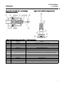
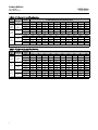
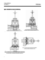
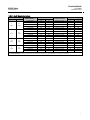
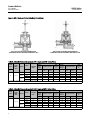
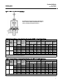
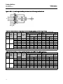
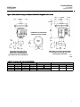
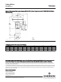
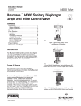
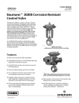
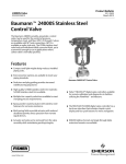
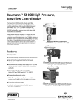
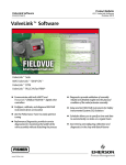
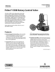
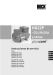
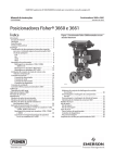
Product Bulletin 84000 Valve 52.1:84000 November 2012 D103343X012 Baumannt 84000 Sanitary Control Valves The Baumann 84000 sanitary control valves are designed to satisfy the stringent demands of the pharmaceutical and biotechnology industries. These valves are in compliance with 3A Sanitary Standards Inc. requirements. Incorporating reliable class III diaphragm technology, the 84000 valves can handle temperatures up to 160_C (320_F). The uniquely shaped diaphragm, unlike plug style sanitary valves, results in low shear forces in the flow stream, minimizing possible damage to delicate bio-media or altering the consistency of end product. W9838 84000 Inline Sanitary Valve with Baumann 32 Actuator Features Electropolished internal surfaces USP 24 Class VI PTFE, EPDM backed diaphragm Designed for Clean-in-Place (CIP) and Sanitize-in-Place (SIP) service Self-draining in preferred mounting mode Compact size, see figures 9 to 10 and tables 14 to 15 FDA approved epoxy powder-coated actuator with stainless steel fasteners for maximum corrosion resistance Stainless steel spring case and yoke available Multi-spring field-reversible actuators with reduced deadband permits direct operation from remote signal devices Fisherr FIELDVUEt digital valve controller available for remote calibration and diagnostics in facilities utilizing the PlantWebt architecture W9839 www.Fisher.com 84000 Angle Sanitary Valve with Baumann 32 Actuator and FIELDVUE DVC2000 Digital Valve Controller W9840 84000 Angle Sanitary Valve with Baumann 54 Actuator and FIELDVUE DVC6000 Digital Valve Controller Product Bulletin 84000 Valve 52.1:84000 November 2012 D103343X012 Figure 1. Baumann 84000 NPS 1 Angle Valve Body Sub-Assembly Figure 2. Baumann 84000 NPS 1 Inline Valve Body Sub-Assembly E1315 E1314 Table 1. Materials of Construction for NPS 1 Angle and Inline Valves 2 Key Number Description Material 1 Valve Body ASTM A479 S31603 stainless steel, annealed 2 Bonnet ASTM A479 S30400 Annealed 3 Piston Stem Sub-assembly Stainless Steel 4 Drive Mechanism Sub-assembly Multiple (predominantly stainless steel) 5 Compressor S30300 or S30400 stainless steel 6 Wave Spring S17700 stainless steel 7 Retaining Ring S30200 stainless steel 8 Diaphragm, Closure Member PTFE face with Aramid fabric reinforced EPDM backing and S30400 stainless steel insert. Diaphragm assembly conforms to FDA 21CFR 177.1550 and USP24 Class VI standards. 9 Drive Nut, Actuator Yoke S30400 stainless steel 11 Bonnet Flange ASTM A240 S30400 stainless steel 13 O-Ring, Stem FKM fluorocarbon 14 Tell Tale Port S31600 stainless steel 18 Hex Head Cap Screw Grade B8, Class 1 27 Locknuts S30400 stainless steel 58 Travel Indicator S30400 stainless steel Product Bulletin 84000 Valve 52.1:84000 November 2012 D103343X012 Figure 3. Baumann 84000 NPS 1-1/2 and 2 Angle Valve Body Sub-Assembly Figure 4. Baumann 84000 Linkage Mechanism E1316 E1317 Table 2. Materials of Construction for NPS 1-1/2 and 2 Angle Valves Key Number Description Material 1 Valve Body ASTM A479 S31603 stainless steel, annealed 2 Bonnet ASTM A479 S30400 Annealed 3 Piston Stem Sub-assembly Stainless Steel 4 Drive Mechanism Sub-assembly Multiple (predominantly stainless steel) 5 Compressor S30300 or S30400 stainless steel 6 Wave Spring S17700 stainless steel 7 Retaining Ring S30200 stainless steel 8 Diaphragm, Closure Member PTFE face with Aramid fabric reinforced EPDM backing and S30400 stainless steel insert. Diaphragm assembly conforms to FDA 21CFR 177.1550 and USP24 Class VI standards. 9 Drive Nut, Actuator Yoke S30400 stainless steel 11 Clamp S30400 stainless steel 13 O-Ring, Stem FKM fluorocarbon 14 Tell Tale Port S31600 stainless steel 15 O-Ring EPDM, conforming to FDA 21CFR 177.1550 27 Locknuts S30400 stainless steel 58 Travel Indicator S30400 stainless steel 3 Product Bulletin 84000 Valve 52.1:84000 November 2012 D103343X012 Table 3. Cv Values at Percent Plug Opening VALVE SIZE NPS FLOW DIRECTION ACTUATOR TRAVEL Inches 10 20 30 40 50 60 70 80 90 100 1 Angle & Inline A to B or B to A 0.50 0.02 0.09 0.20 0.40 0.64 0.90 1.16 1.44 1.72 2.00 0.50 0.03 0.16 0.36 0.90 1.20 1.75 2.30 2.90 3.50 4.00 0.75 0.04 0.24 0.62 1.20 2.00 3.10 4.20 5.50 6.80 8.00 0.50 1.45 3.07 4.86 6.95 9.34 12.0 14.3 16.7 19.1 21.7 0.75 2.18 4.86 8.00 12.0 15.5 19.1 22.9 25.9 28.2 29.6 0.50 1.82 3.61 5.39 7.42 9.66 12.1 13.4 14.6 15.7 17.1 0.75 2.73 5.39 8.43 12.1 14.1 15.7 17.8 20.2 22.5 24.2 0.50 2.60 3.0 3.90 6.94 10.4 14.2 18.4 22.4 26.1 29.4 0.75 2.70 3.90 8.46 14.2 20.5 26.1 31.0 35.3 39.6 42.6 0.50 0.50 0.80 1.35 2.49 5.81 11.3 14.6 17.9 21.5 23.5 0.75 0.50 1.35 3.06 11.3 16.2 21.5 24.5 26.0 29.2 32.5 1-1/2 Angle 2 Angle (1) A to B B to A A to B B to A Cv VERSUS PERCENT OF ACTUATOR TRAVEL OPEN 1. Flow A to B is recommended for low discharge pressure. Low discharge pressure being defined as near or below atmospheric pressure. Table 4. Kv Values at Percent Plug Opening VALVE SIZE DN 25 Angle & Inline 40 Angle 50 Angle FLOW DIRECTION ACTUATOR TRAVEL mm 10 20 30 40 50 60 70 80 90 100 A to B or B to A 12.7 0.017 0.077 0.17 0.34 0.55 0.77 0.998 1.24 1.48 1.72 3.44 (1) A to B B to A A to B B to A Kv VERSUS PERCENT OF ACTUATOR TRAVEL OPEN 12.7 0.026 0.138 0.31 0.77 1.03 1.51 1.98 2.49 3.01 19.05 0.034 0.206 0.53 1.03 1.72 2.67 3.61 4.73 5.85 6.88 12.7 1.25 2.64 4.18 5.98 8.03 10.32 12.29 14.36 16.43 18.66 19.05 1.88 4.18 6.88 10.32 13.33 16.43 19.69 22.27 24.25 25.46 12.7 1.57 3.10 4.64 6.38 8.31 10.41 11.52 12.56 13.50 14.71 19.05 2.35 4.64 7.25 10.41 12.13 13.50 15.31 17.37 19.35 20.81 12.7 2.24 3.0 3.35 5.97 8.94 12.21 15.82 19.26 22.45 25.28 19.05 2.33 3.35 7.28 12.21 17.63 22.45 26.66 30.36 34.06 36.64 12.7 0.43 0.69 1.16 2.14 4.98 9.72 12.56 15.39 18.49 20.21 19.05 0.43 1.16 2.63 9.72 13.93 18.49 21.07 22.36 25.11 27.95 1. Flow A to B is recommended for low discharge pressure. Low discharge pressure being defined as near or below atmospheric pressure. 4 Product Bulletin 84000 Valve 52.1:84000 November 2012 D103343X012 Table 5. Technical Specifications VALVE SIZE RATED NPS 1 Angle & Inline NPS 1-1/2 Angle NPS 2 Angle Installed with flow from Port A to B Cv 2 4 8 22 30 29 43 Kv 1.72 3.44 6.88 18.92 25.8 24.94 36.98 Installed with flow from Port B to A Cv 2 4 8 17 24 24 32 Kv 1.72 3.44 6.88 14.62 20.64 20.64 27.52 mm 12.7 12.7 19.05 12.7 19.05 12.7 19.05 inches 0.50 0.50 0.75 0.50 0.75 0.50 0.75 TRAVEL BONNET Bolted ACTUATOR TYPE 32 or 54 Clamped 54 RANGEABILITY 100:1 CHARACTERISTIC Modified Equal Percentage SEAT LEAKAGE ASME/FCI 70-2, Class VI MAXIMUM OPERATING PRESSURE 10.34 bar (150 Psi) MAXIMUM OPERATING TEMPERATURE 160_C (320_F) INTERNAL BODY FINISH (WETTED INTERIOR) < 30 Ra Microinch / 0.76 Ra Micron (standard) < 20 Ra Microinch / 0.51 Ra Micron (optional - or as required) END CONNECTIONS Sanitary (optional welded ends) Table 6. Actuator Specifications TYPE 32 Multi-Spring Diaphragm (Single-Acting) 54 Multi-Spring Diaphragm (Single-Acting) NOMINAL SIZE 32 in2 54 in2 AIR FAILURE Open or Closed TRAVEL 12.7 to 19.05 mm (0.50 or 0.75 inches) AMBIENT TEMPERATURE RANGE -29 to 82_C (-20 to 180_F) MAXIMUM AIR PRESSURE 2.4 bar (35 psig) DIAPHRAGM MATERIAL Nitrile / Polyester SPRING CASES J Steel, Powder Epoxy-Coated Appliance White per FDA 21 CFR 175.300 or J Stainless Steel FASTENERS Stainless Steel YOKE J Ductile Iron, Powder Epoxy-Coated Appliance White per FDA 21 CFR 175.300 or J Cast Stainless Steel 5 Product Bulletin 84000 Valve 52.1:84000 November 2012 D103343X012 Figure 5. Preferred Flow Directions for Self-Draining NPS 1 INLINE VALVE BODY POSITIONED FOR FORWARD FLOW SELF DRAINING FROM PORT A TO B NPS 1 ANGLE VALVE BODY POSITIONED FOR FORWARD FLOW SELF DRAINING FROM PORT A TO B E1318 E1319 E1321 NPS 1-1/2 AND 2 ANGLE VALVE BODY POSITIONED FOR SELF DRAINING FROM PORT B TO A E1320 NPS 1-1/2 AND 2 ANGLE VALVE BODY (RECOMMENDED FOR PROCESSES WHERE ATMOSPHERIC OR SLIGHT VACUUM IS PRESENT DOWNSTREAM OF PORT B [PORTS A AND B MUST BE DRAINED SEPARATELY) 6 Product Bulletin 84000 Valve 52.1:84000 November 2012 D103343X012 Table 7. Model Numbering System VALVE SIZE NPS 1 Angle 1 Inline 1-1/2 Angle 2 Angle DN 25 Angle 25 Inline 40 Angle 50 Angle MODEL NUMBER(1, 2) TRAVEL Inches mm 32-84021SAB 0.50 12.7 32-84041SAB 0.50 54-84041SAB 0.50 32-84081SAB TYPE (Flow Direction) RATED Cv Kv ANGLE (Port A to B) 2 1.72 12.7 ANGLE (Port A to B) 4 3.44 12.7 ANGLE (Port A to B) 4 3.44 0.75 19.05 ANGLE (Port A to B) 8 6.88 54-84081SAB 0.75 19.05 ANGLE (Port A to B) 8 6.88 32-84021SIB 0.50 12.7 ANGLE (Port A to B) 2 1.72 32-84041SIB 0.50 12.7 ANGLE (Port A to B) 4 3.44 54-84041SIB 0.50 12.7 ANGLE (Port A to B) 4 3.44 32-84081SIB 0.75 19.05 ANGLE (Port A to B) 8 6.88 54-84081SIB 0.75 19.05 ANGLE (Port A to B) 8 6.88 54-84161SAB 0.50 12.7 ANGLE (Port A to B) 22 18.92 54-84351SAB 0.75 19.05 ANGLE (Port A to B) 30 25.8 54-84161SA 0.50 12.7 ANGLE (Port B to A) 17 14.62 54-84351SA 0.75 19.05 ANGLE (Port B to A) 24 20.64 54-84251SAB 0.50 12.7 ANGLE (Port A to B) 29 24.94 54-84431SAB 0.75 19.05 ANGLE (Port A to B) 43 36.98 54-84251SA 0.50 12.7 ANGLE (Port B to A) 24 20.64 54-84431SA 0.75 19.05 ANGLE (Port B to A) 32 27.52 1. Model descriptor SA designates an angle valve body. Model descriptor SI designates an inline valve body. 2. Tri-Clamp end connections are standard. For optional welded end connections, substitute (2) for (1) in the model number, i.e. 54-84161SA (Tri-Clamp Ends). 54-84162SA (Welded Ends). 7 Product Bulletin 84000 Valve 52.1:84000 November 2012 D103343X012 Figure 6. NPS 1 Angle and Inline Valve Body Orientations A A B E1319 E1318 B NPS 1 INLINE VALVE BODY POSITIONED FOR FORWARD FLOW SELF DRAINING FROM PORT A TO B NPS 1 ANGLE VALVE BODY POSITIONED FOR FORWARD FLOW SELF DRAINING FROM PORT A TO B Table 8. Allowable Pressure Drops (bar): NPS 1 Angle and NPS 1 Inline Valves AIR-TO-OPEN ACTION VALVE SIZE FLOW DIRECTION TRAVEL RATED Kv DN A to B 3.44 6.88 Signal to Actuator AIR-TO-CLOSE ACTION With Positioner (2) Bench Spring Range bar bar 0.07-1.2 bar(1) 8.62 With Positioner (2) 12.7 32 0.3-1.0 8.62 0.2-0.9 0.2-1.0 bar 6.9 12.7 32 0.3-1.0 6.9 10.34 10.34 0.2-0.9 6.9 8.62 8.62 12.7 54 0.3-1.0 10.34 10.34 10.34 0.2-0.9 10.34 10.34 10.34 19.05 32 0.3-1.0 3.45 8.62 8.62 0.2-0.9 3.45 8.62 8.62 19.05 54 0.5-0.9 6.9 10.34 10.34 0.2-0.7 6.9 10.34 10.34 bar 0.07-1.2 bar(1) 8.62 Signal to Actuator 0.2-1.0 bar 7.58 mm 1.72 25 ACTUATOR TYPE Bench Spring Range bar 8.62 1. I/P transducer with 0.07 - 1.2 bar (1 - 17 psig) output signal per FCI 87.2. 2. Shutoff with positioner based on 1.4 bar (20 psi) air supply pressure. Table 9. Allowable Pressure Drops (psi): NPS 1 Angle and NPS 1 Inline Valves AIR-TO-OPEN ACTION VALVE SIZE FLOW DIRECTION RATED Cv NPS ACTUATOR TYPE Inches 2.00 1 TRAVEL A to B 4.00 8.00 AIR-TO-CLOSE ACTION Signal to Actuator With Positioner 3-15 psig 1-2 psig(1) psig Bench Spring Range psig (2) Signal to Actuator With Positioner 3-15 psig 1-2 psig(1) psig (2) 0.50 32 5-15 110 125 125 3-13 100 125 125 0.50 32 5-15 100 150 150 3-13 100 125 125 0.50 54 5-15 150 150 150 3-13 150 150 150 0.75 32 5-15 50 125 125 3-13 50 125 125 0.75 54 7-13 100 150 150 3-10 100 150 150 1. I/P transducer with 0.07 - 1.2 bar (1 - 17 psig) output signal per FCI 87.2. 2. Shutoff with positioner based on 1.4 bar (20 psi) air supply pressure. 8 Bench Spring Range psig Product Bulletin 84000 Valve 52.1:84000 November 2012 D103343X012 Figure 7. NPS 1-1/2 and 2 Angle Valve Body RECOMMENDED FOR PROCESSES WHERE ATMOSPHERIC OR SLIGHT VACUUM IS PRESENT DOWNSTREAM OF PORT B. (PORTS A AND B MUST BE DRAINED SEPARATELY) A E1320 B Table 10. Allowable Pressure Drops (bar): Flow Direction A to B: NPS 1-1/2 and 2 Angle Valves AIR-TO-OPEN ACTION VALVE SIZE FLOW DIRECTION TRAVEL RATED Kv DN 40 50 ACTUATOR TYPE mm A to B A to B Bench Spring Range Signal to Actuator AIR-TO-CLOSE ACTION With Positioner (2) bar 0.2-1.0 bar 0.07-1.2 bar(1) bar Bench Spring Range Signal to Actuator With Positioner (2) bar 0.2-1.0 bar 0.07-1.2 bar(1) bar 18.92 12.7 54 0.3-1.0 1.99 3.99 3.99 0.2-0.9 1.99 3.99 6.96 18.92 12.7 54 0.6-1.0 4.96 6.96 6.96 0.2-0.7 4.96 6.96 9.99 25.8 19.05 54 0.3-1.0 1.99 3.99 3.99 0.2-0.9 1.99 3.99 6.96 25.8 19.05 54 0.5-0.9 3.99 5.99 5.99 0.2-0.7 4.92 6.96 9.99 24.94 12.7 54 0.3-1.0 2.34 4.68 4.68 0.2-0.9 2.34 4.68 8.20 24.94 12.7 54 0.6-1.0 5.86 8.20 8.20 0.2-0.7 5.79 8.20 11.72 36.98 19.05 54 0.3-1.0 2.34 4.68 4.68 0.2-0.9 2.34 4.68 8.20 36.98 19.05 54 0.5-0.9 4.68 7.03 7.03 0.2-0.7 5.86 8.20 11.72 1. I/P transducer with 0.07 - 1.2 bar (1 - 17 psig) output signal per FCI 87.2. 2. Shutoff with positioner based on 1.4 bar (20 psi) air supply pressure. Table 11. Allowable Pressure Drops (psi): Flow Direction A to B: NPS 1-1/2 and 2 Angle Valves AIR-TO-OPEN ACTION VALVE SIZE FLOW DIRECTION 3-15 psig 1-2 psig(1) psig 3-15 psig 1-2 psig(1) 22 0.50 54 5-15 29 58 58 3-13 29 58 101 22 0.50 54 8-15 72 101 101 3-10 72 101 145 30 0.75 54 5-15 29 58 58 3-13 29 58 101 30 0.75 54 7-13 58 87 87 3-10 72 101 145 29 0.50 54 5-15 34 68 68 3-13 34 68 119 29 0.50 54 8-15 85 119 119 3-10 84 119 170 43 0.75 54 5-15 34 68 68 3-13 34 68 119 43 0.75 54 7-13 68 102 102 3-10 85 119 170 RATED Cv NPS 1-1/2 2 ACTUATOR TYPE Inches A to B A to B Bench Spring Range psig AIR-TO-CLOSE ACTION Bench Spring Range psig TRAVEL Signal to Actuator With Positioner (2) Signal to Actuator With Positioner (2) psig 1. I/P transducer with 0.07 - 1.2 bar (1 - 17 psig) output signal per FCI 87.2. 2. Shutoff with positioner based on 1.4 bar (20 psi) air supply pressure. 9 Product Bulletin 84000 Valve 52.1:84000 November 2012 D103343X012 Figure 8. NPS 1-1/2 and 2 Angle Valve Body Positioned for Self Draining from Port B to A B E1321 A Table 12. Allowable Pressure Drops (bar): Flow Direction B to A: NPS 1-1/2 and 2 Angle Valves AIR-TO-OPEN ACTION VALVE SIZE FLOW DIRECTION TRAVEL RATED Kv 50 B to A (2) Bench Spring Range bar bar With Positioner (2) 14.62 12.7 54 0.3-1.0 10.20 0.2-0.9 14.62 12.7 54 0.6-1.0 12.76 17.86 17.86 0.2-0.7 12.76 17.86 25.58 20.64 19.05 54 0.3-1.0 5.10 10.20 10.20 0.2-0.9 5.10 10.20 17.86 20.64 19.05 54 0.5-0.9 10.20 15.31 15.31 0.2-0.7 12.76 17.86 25.58 20.64 12.7 54 0.3-1.0 2.90 5.79 5.79 0.2-0.9 2.90 5.79 10.14 20.64 12.7 54 0.6-1.0 7.24 10.14 10.14 0.2-0.7 7.24 10.14 14.48 27.52 19.05 54 0.3-1.0 2.90 5.79 5.79 0.2-0.9 2.90 5.79 10.14 27.52 19.05 54 0.5-0.9 5.79 8.69 8.69 0.2-0.7 7.24 10.14 14.48 bar 0.07-1.2 bar(1) 10.20 Signal to Actuator 0.2-1.0 bar 5.10 mm B to A Signal to Actuator AIR-TO-CLOSE ACTION With Positioner 0.2-1.0 bar 5.10 DN 40 ACTUATOR TYPE Bench Spring Range 0.07-1.2 bar(1) 10.20 17.86 bar 1. I/P transducer with 0.07 - 1.2 bar (1 - 17 psig) output signal per FCI 87.2. 2. Shutoff with positioner based on 1.4 bar (20 psi) air supply pressure. Table 13. Allowable Pressure Drops (psi): Flow Direction B to A: NPS 1-1/2 and 2 Angle Valves AIR-TO-OPEN ACTION VALVE SIZE FLOW DIRECTION 3-15 psig 1-2 psig(1) psig 3-15 psig 1-2 psig(1) 17 0.50 54 5-15 74 148 148 3-13 74 148 259 17 0.50 54 8-15 185 259 259 3-10 185 259 371 24 0.75 54 5-15 74 148 148 3-13 74 148 259 24 0.75 54 7-13 148 222 222 3-10 185 259 371 24 0.50 54 5-15 42 84 84 3-13 42 84 147 24 0.50 54 8-15 105 147 147 3-10 105 147 210 32 0.75 54 5-15 42 84 84 3-13 42 84 147 32 0.75 54 7-13 84 126 126 3-10 105 147 210 NPS 1-1/2 2 TRAVEL ACTUATOR TYPE Inches B to A B to A 1. I/P transducer with 0.07 - 1.2 bar (1 - 17 psig) output signal per FCI 87.2. 2. Shutoff with positioner based on 1.4 bar (20 psi) air supply pressure. 10 AIR-TO-CLOSE ACTION Bench Spring Range psig RATED Cv Bench Spring Range psig Signal to Actuator With Positioner (2) Signal to Actuator With Positioner (2) psig Product Bulletin 84000 Valve 52.1:84000 November 2012 D103343X012 Figure 9. Dimensional Drawings for Baumann 84000 NPS 1 Angle and Inline Valves 249 (9.8) 216 (48.5) 216 (48.5) 31 (1.24) 227 (9.0) BAUMANN 32 ACTUATOR WITH FIELDVUE DVC2000, TOP VIEW 85 (3.4) 85 (3.4) 127 (5.00) 40 (1.6) 84 (3.3) 32 (1.3) 166 (6.52) 84000 ANGLE VALVE BODY WITH BAUMANN 32 ACTUATOR ATC/FO ACTION, DUAL STOP AND FIELDVUE DVC2000 DIGITAL VALVE CONTROLLER 148 (5.8) 84000 INLINE VALVE BODY WITH BAUMANN 32 ACTUATOR ATC/FC ACTION, DUAL STOP AND 3660/3661 POSITIONER mm (inch) E1322 Table 14. Valve Assembly and Actuator Weights VALVE SIZE 84000 ANGLE ASSEMBLY 84000 IN-LINE ASSEMBLY ACTUATOR WEIGHTS DN NPS kgs lbs kgs lbs TYPE kgs lbs 25 1 4.06 9.0 4.31 9.5 32 4.5 10 40 1-1/2 5.22 11.5 N/A 50 2 5.22 11.5 N/A 54 11.3 25 11 Product Bulletin 84000 Valve 52.1:84000 November 2012 D103343X012 Figure 10. Dimensional Drawing for Baumann 84000 NPS 1-1/2 and 2 Angle Valve with FIELDVUE DVC6010 Digital Valve Controller 359 (14.5) 279 (411.0) 276 (10.9) C D F G mm (inch) E E1323 Note: Actuator removal requires 115mm (4.5 inches) vertical clearance. Table 15. Valve Assembly and Actuator Weights VALVE SIZE C D E F G DN NPS mm inch mm inch mm inch mm inch mm inch 40 1-1/2 152.4 6.0 50.8 2.00 82.55 3.25 50.39 1.984 34.44 1.356 50 2 160 6.3 50.8 2.00 88.9 3.50 63.9 2.516 47.63 1.875 Neither Emerson, Emerson Process Management, nor any of their affiliated entities assumes responsibility for the selection, use or maintenance of any product. Responsibility for proper selection, use, and maintenance of any product remains solely with the purchaser and end user. Baumann, Fisher, FIELDVUE, and PlantWeb are marks owned by one of the companies in the Emerson Process Management business unit of Emerson Electric Co. Emerson Process Management, Emerson, and the Emerson logo are trademarks and service marks of Emerson Electric Co. All other marks are the property of their respective owners. The contents of this publication are presented for informational purposes only, and while every effort has been made to ensure their accuracy, they are not to be construed as warranties or guarantees, express or implied, regarding the products or services described herein or their use or applicability. All sales are governed by our terms and conditions, which are available upon request. We reserve the right to modify or improve the designs or specifications of such products at any time without notice. Emerson Process Management Marshalltown, Iowa 50158 USA Sorocaba, 18087 Brazil Chatham, Kent ME4 4QZ UK Dubai, United Arab Emirates Singapore 128461 Singapore www.Fisher.com E 122009, 2012 Fisher Controls International LLC. All rights reserved.