1
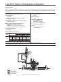
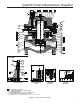
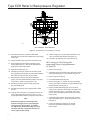
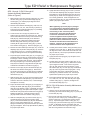
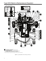
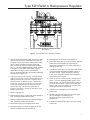
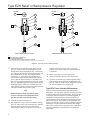
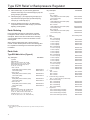
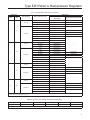
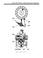
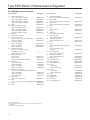
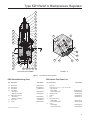
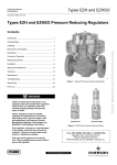
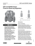
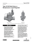
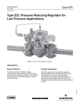
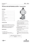
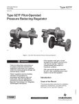
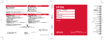
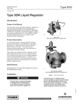
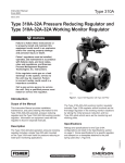
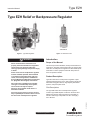
Type EZH
Instruction Manual
September 2013
Type EZH Relief or Backpressure Regulator
TYPE PRX/182
Figure 1. Type EZH Regulator
!
Figure 2. PRX Series Pilot
Introduction
WARNING
Failure to follow these instructions or to
properly install and maintain this equipment
could result in an explosion and/or fire
causing property damage and personal injury
or death.
Fisher® relief valve or backpressure regulator
must be installed, operated, and maintained
in accordance with federal, state, and local
codes, rules and regulations, and Emerson
Process Management Regulator Technologies,
Inc. (Regulator Technologies) instructions.
If the relief valve or backpressure regulator
vents gas or a leak develops in the system,
service to the unit may be required.
Failure to correct trouble could result in a
hazardous condition.
This manual provides installation, startup and maintenance
instructions, and parts ordering information for theType EZH
relief valve or backpressure regulator and PRX Series pilots.
Information on other equipment used with this product is
found in separate manuals.
Product Description
Type EZH relief valve or backpressure regulator is pilotoperated and designed for use in high pressure natural gas
transmission/city gate stations, large capacity distribution
systems, and power plant feeds.
Pilot Descriptions
The Type EZH relief valve or backpressure regulator
include a Type PRX/182 pilot mounted on the main valve.
PRX Series pressure reducing pilots have the ability to
handle a wide range of setpoints from 29 to 1160 psig /
2.0 to 80.0 bar.
D103078X012
Call a gas service person to service the unit.
Only a qualified person must install or service
the relief valve or backpressure regulator.
Scope of the Manual
www.fisherregulators.com
Type EZH Relief or Backpressure Regulator
Specifications
Ratings and specifications for the Type EZH are listed in the Specifications section below. Specifications for specific relief
valve or backpressure regulator constructions are stamped on a nameplate attached to either the main actuator or the pilot
spring case.
Pressure Registration
External
Body Sizes, End Connection Styles, and
Pressure Ratings(1)
See Table 1
Pilot Connections
1/4 NPT
Maximum Inlet and Outlet (Casing) Pressures(1)
1500 psig / 103 bar
Temperature Capabilities(1)
Nitrile (NBR) Version:
-20 to 180ºF / -29 to 82ºC
Fluorocarbon (FKM) Version:
0 to 180ºF / -18 to 82ºC(2)
Maximum Emergency (Design Casing Pressure)(1)
1500 psig / 103 bar
Maximum Operating Differential Pressure(1)
Main Valve: 1500 psid / 103 bar d
Pilot (Between loading pressure in pilot and
loading sense pressure): 1233 psid / 85.0 bar d
Options
• Pre-piped Pilot Supply
• Travel Indicator
Outlet Pressure Ranges
See Table 2
Minimum Differential Pressures(1)
TYPE
EZH
MAIN VALVE
BODY SIZE
MINIMUM DIFFERENTIAL
For 90% Capacity
For 100% Capacity
NPS
DN
psid
bar d
psid
1
25
15.2
1.1
15.7
bar d
1.1
2
50
12.0
0.83
13.8
0.95
3
80
10.6
0.73
12.8
0.88
4
100
15.8
1.1
16.4
1.1
1. The pressure/temperature limits in this Instructional Manual and any applicable standard or code limitation should not be exceeded.
2. Type PRX Fluorocarbon (FKM) elastomer is limited to 0°F / -18°C.
PORT L
PORT S
SPRING
CASE VENT
PORT B
EXHAUST
PORT A
M1055
INLET PRESSURE
OUTLET PRESSURE
ATMOSPHERIC PRESSURE
LOADING PRESSURE
Figure 3. Type EZH with Type PRX/182 Pilot
2
Type EZH Relief or Backpressure Regulator
Table 1. Main Valve Body Sizes, End Connection Styles, and Body Ratings
MAIN VALVE BODY SIZE
NPS
MAIN VALVE BODY MATERIAL
DN
1
psig
bar
NPT or SWE
1500
103
CL150 RF
290
20.0
CL300 RF
750
51.7
CL600 RF or BWE
1500
103
NPT or SWE
1500
103
CL150 RF
290
20.0
51.7
25
2
50
WCC Steel
3
CL300 RF
750
CL600 RF or BWE
1500
103
CL150 RF
290
20.0
51.7
80
4
STRUCTURAL DESIGN RATING
END CONNECTION STYLE
CL300 RF
750
CL600 RF or BWE
1500
103
CL150 RF
290
20.0
CL300 RF
750
51.7
CL600 RF or BWE
1500
103
100
Table 2. Relief Set Pressure Ranges
PILOT
TYPE
RELIEF SET
PRESSURE RANGE
PILOT CONTROL INFORMATION
Wire Diameter
Free Length
Maximum
Operating
Pressure
Maximum
Emergency
Pressure
Part Number
Color
Inch
mm
Inch
mm
psig
bar
psig
bar
2.0 to 8.0
5.0 to 20.0
15.0 to 42.0
GD25522X012
GD25520X012
GD25519X012
Black
Gold
Red
0.157
0.197
0.236
3.99
5.00
5.99
2.16
2.01
2.01
55
51
51
609
42.0
1480
102
30.0 to 80.0
GD27379X012
Clear
0.335
8.51
3.94
100
1160
80.0
1480
102
psig
bar
PRX/182
29 to 116
73 to 290
217 to 609
PRX-AP/182
435 to 1160
Principle of Operation
A pressure relief valve is a throttling pressure control device
that opens and closes to ensure the inlet pressure does not
rise above a predetermined pressure. Fisher® relief valves
cannot be used as ASME safety relief valves. A backpressure
regulator is a device that controls and responds to changes in
the upstream pressure. It functions the same as a relief valve
in that it opens on increasing upstream pressure.
Relief Valve
As long as the inlet pressure is below the set pressure, the pilot
control spring keeps the pilot valve plug closed. Inlet pressure
passes through the restrictor and registers as loading pressure
on the main valve diaphragm chamber. Force from the main
spring, in addition to pilot loading pressure, provide loading
pressure to keep the main valve diaphragm and plug assembly
tightly shut off. When the inlet pressure rises above the set
pressure, the pressure on the pilot diaphragm overcomes
the pilot control spring and opens the pilot valve plug. The
pilot then exhausts the loading pressure from the main valve
diaphragm chamber. The pilot continuously exhausts gas when
the inlet pressure is above the set pressure. The inlet pressure
unbalance overcomes the main spring force and opens the
diaphragm and plug assembly.
As the inlet pressure drops below the set pressure, the pilot
control spring closes the pilot valve plug and the exhaust to
atmosphere stops. Force from the main spring, along with pilot
loading pressure, pushes the diaphragm and plug assembly
onto the knife-edged seat, producing tight shutoff.
Backpressure Regulator
As long as inlet pressure remains below setpoint, the
pilot control spring keeps the pilot valve plug closed. Inlet
pressure passes through the upper port around the upper
portion of the valve plug and then through the hollow passage
in that valve plug. Force from the main spring, in addition to
pilot loading pressure, provide downward loading pressure to
keep the main valve diaphragm and plug assembly tightly shut
off. When inlet pressure rises above the set pressure, pressure
on the pilot diaphragm overcomes the control spring to close
the upper port and stroke the valve plug to open the lower
port. The pilot exhausts loading pressure from the main valve
diaphragm chamber. Inlet pressure unbalance overcomes the
main spring force to open the diaphragm and plug assembly.
While the main valve is throttling, the upper port of the pilot
stays closed. The pilot exhausts only when it repositions the
main valve. As inlet pressure drops below setpoint, the pilot
control spring overcomes the diaphragm force to stroke the
valve plug down to close the lower port and open the upper
port. Force from the main spring, along with pilot loading
pressure, pushes the diaphragm and plug assembly onto the
knife-edged seat, producing tight shutoff.
3
Type EZH Relief or Backpressure Regulator
Type EZH
CAUTION
Type EZH Single-Pilot Relief Valve or
Backpressure Regulator
Type EZH Adjustment
The adjustment of setpoint (Figure 7), is performed by means
of the pilot adjusting screw, which varies the compression of
the control spring. Adjustment is performed while the relief
valve or backpressure regulator is in operation with the aid of a
pressure gauge to monitor upstream pressure.
Loosen the Type PRX pilot locknut and turn the adjusting screw
slowly clockwise to increase set pressure and counterclockwise
to decrease set pressure. Use a pressure gauge to monitor
the set pressure until the desired opening pressure is reached.
CAUTION
Personal injury or equipment damage, due
to bursting of pressure-containing parts may
result if this relief valve or backpressure
regulator is overpressured or is installed
where service conditions could exceed the
product and pilot pressure ratings.
Installation
After assembly, check for shutoff and leakage
to atmosphere.
2. A
Type EZH relief valve or backpressure regulator may
be installed in any orientation, as long as flow through it
matches the direction of the arrow on the main valve body.
3. A
pply pipe compound to the external pipeline threads
before installing a relief valve or backpressure regulator
with threaded NPT end connections. Use gaskets between
pipeline and relief valve or backpressure regulator flanges
when installing a relief valve or backpressure regulator
with flanged end connections. When installing butt weld
end connections, remove trim before welding and make
sure to use approved welding practices. Use approved
piping procedures when installing the relief valve or
backpressure regulator.
!
!
WARNING
Personal injury, equipment damage, or
leakage due to escaping gas or bursting of
pressure-containing parts may result if the
Type EZH is installed where its capabilities
can be exceeded or where conditions
exceed any ratings of the adjacent piping or
connections. To avoid this, install a Type EZH
relief valve or backpressure regulator where:
• Service conditions are within unit
capabilities (including those in the
Specifications section).
• Service conditions are within applicable
codes, regulations, or standards.
Additionally, physical damage to the relief
valve or backpressure regulator could break
the pilot off the main valve, causing personal
injury and property damage due to escaping
gas. To avoid such injury or damage, install
the unit in a safe location.
1. O
nly personnel qualified through training and
experience should install, operate, and maintain a relief
valve or backpressure regulator. Before installation,
make sure that there is no damage to, or debris in
the main valve body or pilot. Also, make sure that all
tubing and piping are clean and unobstructed.
4
When installing Type EZH trim in an existing
Fisher® E-body, damage can result if flow is not
in the correct direction. Look at the body web
to confirm that flow is in the correct direction—
up through the center of the cage and down
through the cage slots. Change the existing
flow arrow if necessary.
WARNING
When used in relief valve service, the Type EZH
main valve and pilot both exhaust gas. In
hazardous or flammable gas service, personal
injury, death, or property damage may occur
due to fire or explosion of vented gas that
has accumulated. To prevent such injury or
damage, provide piping or tubing to vent the
gas to a safe location. The exhaust piping
must be designed and installed to guard
against excessive flow restriction. This piping
must be protected against condensation or
debris that could clog it.
For safety during shutdown, vent valves
are required immediately upstream
and downstream of the main valve on a
backpressure or bypass installation.
4. If system operation during maintenance is required, install
isolating and vent valves as needed.
5. F
or the Type PRX/182 pilot, if the vent assembly (key 12,
Figure 7) remains in the pilot body (key 1, Figure 7), then
it must be pointed down if possible or otherwise protected.
If the exhaust is to be piped to the main valve exhaust or
remotely vented, remove the vent assembly and install
tubing or piping into the 1/4 NPT pilot exhaust connection.
Protect the open end of the exhaust pipe by installing a
screened vent cap.
Type EZH Relief or Backpressure Regulator
6. T
he Type PRX/182 pilot spring case vent (key 12,
Figure 7) must be kept open to atmospheric pressure.
Protect the vent assembly from icing, moisture, or debris
that may cause blockage, as required. To change the
vent orientation, twist the vent assembly in the spring
case. To remotely vent the pilot spring case, remove the
vent assembly and install tubing or piping into the 1/4 NPT
spring case vent tapping. Protect the open end of the vent
line by installing a screened vent cap.
7. T
he Type PRX pilot connections are 1/4 NPT. Connect
the inlet control (sense) line from the “A” port, Figure 6
(key 47) on the bottom of the PRX Series pilot to a straight
run of pipe 6 to 10 pipe diameters from the relief valve or
backpressure regulator inlet as shown in Figure 3 using
3/8-inch / 9.5 mm or larger outside diameter tubing. If such
a distance is not practical, connect the control line away
from elbows, swages, nipples, or any area where abnormal
flow velocities occur.
Startup and Shutdown
CAUTION
If pressure is introduced first to the main
valve before the pilot, the main valve may
go wide-open and subject the downstream
system to full inlet pressure.
Note
The maximum inlet pressure for specific
constructions are given in Table 6. Use a
pressure gauge to monitor inlet pressure
during startup.
Relief Installation (Figure 6)
Startup
1. Close vent valve (not shown).
2. Slowly open block valve and hand valve, if installed.
3. Adjust the pilot as needed.
Shutdown
1. Close block valve and hand valve, if installed.
2. Slowly open vent valve (not shown).
Backpressure Installation
Startup
1. Close upstream and downstream vent valves
(not shown).
2. Slowly open upstream block valve first and then slowly
open downstream block valve.
3. Adjust the pilot as needed. If the pilot is not piped
downstream, make sure the pilot exhaust is pointed in
the correct direction.
Shutdown
1. C
lose upstream block valve first and then close the
downstream block valve.
2. O
pen downstream and upstream vent valves
(not shown).
Type PRX/182 Pilot Adjustment
For PRX Series pilots (Figure 7), loosen locknut
(key 2) and turn the adjusting screw into the spring case
to increase (or out of the spring case to decrease) the
downstream pressure. When the required downstream
pressure is maintained for several minutes, tighten the
locknut to lock the adjusting screw in position.
!
WARNING
Avoid personal injury or damage to property
from sudden release of pressure or
uncontrolled gas or other process fluid. Before
starting to disassemble, carefully release
all pressures according to the appropriate
shutdown procedure. Use a gauge to monitor
relief (inlet) pressure while releasing it.
CAUTION
Use proper lifting techniques, when lifting the
upper and lower actuator casings (keys 11
and 5) off the Type EZH body (key 1). The
actuator assembly weighs more than
100 pounds / 45 kg.
Customer cannot use another type of eyebolt
in the regulator. Only Regulator Technologies
parts can be used to repair the unit.
Eye bolts are installed to aid in the handling
and installation of the Regulator Assembly
only. Do not attempt to lift more weight than
the regulator with these eye bolts.
Maintenance
Relief valve or backpressure regulator parts are subject
to normal wear and must be inspected periodically and
replaced as necessary. Due to the care Fisher® takes in
meeting all manufacturing requirements (heat treating,
dimensional tolerances, etc.), use only replacement parts
manufactured or furnished by Fisher. Also when lubrication
is required, use a good quality lubricant and sparingly coat
the recommended parts.
The frequency of inspection and replacement depends upon
the severity of service conditions and upon applicable codes,
government regulations, and company standards.
5
Type EZH Relief or Backpressure Regulator
Table 3. Torque Specifications
TORQUE SPECIFICATIONS
Body Size
PART NAME
Indicator Fitting or Plug (key 141)
NPS 1 / DN 25
NPS 2 / DN 50
NPS 3 / DN 80
NPS 4 / DN 100
foot-pound
N•m
foot-pound
N•m
foot-pound
N•m
foot-pound
N•m
10 to 30
14 to 41
10 to 30
14 to 41
10 to 30
14 to 41
10 to 30
14 to 41
Stud Nuts (key 26)
45 to 50
61 to 68
45 to 50
61 to 68
80 to 95
108 to 129
Socket Head Cap Screws (key 16)
50 to 70(1)
5.6 to 7.9
50 to 70(1)
6 to 7.9
50 to 70(1)
6.2 to 7.9
----
Stud Bolts (key 24)
50 to 70
68 to 95
50 to 70
68 to 75
100 to 120
136 to 163
Cap Screws (key 21)
50 to 55
68 to 75
130 to 150
176 to 203
250 to 270
339 to 366
280 to 310
380 to 420
Cap Screws (key 6)
50 to 60
68 to 81
50 to 60
68 to 81
70 to 95
95 to 129
140 to 155
190 to 210
Socket Head Cap Screws (key 33)
30 to 40(1)
3.4 to 4.5
50 to 60(1)
5.6 to 6.8
80 to 100(1)
9 to 11
80 to 100(1)
9 to 11
----
31 to 40(1)
3.5 to 4.5
100 to 115(1)
11 to 13
----
Smart Screws (key 68)
----
----
Socket Head Cap Screws (key 74)
----
----
----
26 to 35(1)
2.9 to 4
Cap Screws (key 77)
----
----
----
90 to 110
122 to 149
Sleeve Guide (key 61)
130 to 140
176 to 190
Cap Screw (key 154)
16(1)
1.8
50(1)
5.6
10
14
2.9 to 3.5
3.9 to 4.7
Stem Nut (key 151)
32
43
32
43
45
61
45 to 50
Stem Nut (key 155)
30
41
Hex Nut (key 152)
----
----
----
----
---40
---54
60
61 to 68
----
81
45 to 50
61 to 68
1. Torque specifications are given in inch-pounds.
Main Valve and Actuator Maintenance
NPS 1 through 3 / DN 25 through 80
Disk Maintenance (Refer to Figure 4)
For Type EZH:
NPS 4 / DN 100 Disk Maintenance
(Refer to Figure 4)
1. Remove nuts (key 26).
1. Remove cap screws (key 77).
2. Carefully lift the upper actuator casing and lower actuator
casing assembly (keys 11 and 5) off the body (key 1).
2. Carefully lift the cap (key 70) off the upper actuator
casing (key 11) and unscrew the eye bolts (key 35) from
the cap (key 70).
3. Remove the hex socket cap screws (key 33) and lock
washers (key 32). Lift off the disk holder assembly
(key 30) and disk retainer (key 31).
4. Remove the O-ring (key 29). Inspect the O-ring for
damage or wear, and replace if necessary. Lightly
lubricate O-ring before placing in the sleeve adaptor
(key 27).
5. Remove the cage (key 3), seat ring (key 2) and O-ring
(key 34). Inspect the O-ring for damage or wear, and
replace if necessary. Lightly lubricate O-ring before
placing in the body (key 1).
6. Set the seat ring (key 2) back in the body (key 1) with the
curved side down and the seat edge up. Place the cage
(key 3) on top of seat ring. The cage will engage the step
on the seat ring.
7. Place the disk holder assembly (key 30) and disk retainer
(key 31) on the sleeve adaptor (key 27).
8. Insert the lock washers (key 32) and hex socket cap
screws (key 33) and tighten. See Torque Specifications
(Table 3) for proper torque values.
9. Carefully lift the upper actuator casing and lower
actuator casing assembly (keys 11 and 5) and place
6
on the body (key 1). Secure with stud bolts and nuts
(keys 24 and 26). See Torque Specifications (Table 3) for
proper torque values.
3. Remove O-ring (key 75). Inspect the O-ring for damage
or wear, and replace if necessary.
4. Remove the O-ring (key 69). Inspect the O-ring for
damage or wear, and replace if necessary. Lubricate
O-ring before placing inside the cap (key 70).
5. Remove special screws (key 68) from sleeve (key 14).
6. Fit eye bolt (key 35) into the upper spring seat (key 73)
threaded hole.
7. Carefully remove the trim system from the sleeve guide
(key 61) using the eye bolts (key 35).
8. Remove socket head cap screws (key 33) and lock
washers (key 32).
9. Lift off the disk retainer (key 31) and disk holder assembly
(key 30).
10. Remove the O-ring (key 29). Inspect the O-ring for
damage or wear, replace if necessary. Lightly lubricate
O-ring before placing the sleeve adaptor (key 27).
11. Place disk holder assembly (key 30) onto disk retainer
(key 31).
Type EZH Relief or Backpressure Regulator
L1
44
13 14
L2 L2
4
8 10
L2 L2 L2
9
L2
L1
8 15 16 17 18 19 20
10
21
22
11
23
10
24
25
L2 62
26
L2 8
L2 9
6
L2 8
27 S1
28 L2
L2 7
29 L2
5
30
L2 4
31
32
3
33 S1
2
34 L2
1
32
33 S1
TOP VIEW
140
160
138
139
140
38
141
L2 143
142B
L2 143
35
L2
145
144
IMPROVED TRAVEL
INDICATOR DETAIL
6
S2
VERSION WITHOUT
TRAVEL INDICATOR
DETAIL
FOR NPS 1 / DN 25
EZH SERIES
VERSION ONLY
FOR NPS 3 / DN 80
EZH SERIES
VERSION ONLY
NPS 1 THROUGH 3 / DN 25 THROUGH 80
GD89918_H
APPLY LUBRICANT (L) / SEALANT (S)(1):
L1 = LITHIUM HYDROXYSTEGRATE NLGI 2 GRADE GREASE
L2 = SILICONE-BASED GREASE
S1 = ANAEROBIC METHACRYLATE SEALANT FOR NUTS AND BOLTS
S2 = ANAEROBIC METHACRYLATE SEALANT FOR THREADS
1. Lubricant and sealant must be selected such that they meet the temperature requirements.
Figure 4. Type EZH Main Valve Assembly
7
Type EZH Relief or Backpressure Regulator
L1
13 14
L2 L2
L2 L2
4
8
10
9
8
L2
L1
15 16 17 18 19
20
L2
35
43
10
39
21
22
23
36
24
37
25
26
6
27 S1
59 37
28 L2
29 L2
60
30
31
32
33 S1
34 L2
32
GD89918_J33 S1
NPS 1 THROUGH 3 / DN 25 THROUGH 80
8
L2 143
35
Figure 4. Type EZH Main Valve Assembly (continued)
12. Place
disk retainer (key 31) with the disk holder
6
assembly (key 30) into sleeve adaptor (key 27) and align
screw holes.
13. Place lock washer (key 32) onto the screws (key 33).
14. Screw together the disk retainer assembly into the
sleeve adaptor (key 27). See Torque Specifications
(Table 3) for proper torque values.
22. Screw the eye bolts (key 35) on the cap (key 70).
NPS 1 through 3 / DN 25 through 80
Intermediate Flange O-ring Maintenance
for Type EZH
15. Lubricate the sleeve (key 14).
1. Remove nuts (key 26).
16. Carefully insert the trim system into the sleeve guide
(key 61) utilizing eye bolt (key 35). Align sleeve utilizing
the socket hex cap screw (key 74) as a guide.
2. Carefully lift the upper actuator casing and lower actuator
casing assemblies (keys 11 and 5) off the body (key 1).
17. Screw special screws (key 68) to affix the sleeve
system. See Torque Specifications (Table 3) for proper
torque values. Place O-ring (key 69) on cap.
4. Lift off intermediate flange (key 25).
18. Remove eye bolt (key 35) from upper spring seat
(key 73) threaded hole.
19. Carefully place the cap on the upper actuator casing
(key 11).
20. Lubricate cap screws (key 77) and attach cap (key 70)
to the upper casing using cap screws (key 77). See
Torque Specifications (Table 3) for proper torque values.
Note
Rotate the cap (key 70) such that the outer
holes for sensing lines are in line with upper
casing holes for sensing lines. To validate
the alignment and before attaching cap, check
that travel indicator is aligned on the cap and
on the upper actuator casing.
8
21. Mount O-ring (key 75) on the space between the cap
(key 70) and the upper actuator casing (key 11).
3. Remove cap screws (key 6).
5. Remove O-ring (key 7). Inspect the O-ring for damage
or wear, and replace if necessary. Lightly lubricate O-ring
before placing in the body (key 1).
6. Place the intermediate flange (key 25) on the body,
make sure to position the stud bolt (key 24) holes on the
outsides of the body (key 1). Secure with cap screws
(key 6). See Torque Specifications (Table 3) for proper
torque values.
7. Carefully lift upper actuator casing and lower actuator
casing assemblies (keys 11 and 5) and position it in the
body (key 1).
8. Screw in stud bolts and nuts (keys 24 and 26).
See Torque Specifications (Table 3) for proper
torque values.
Type EZH Relief or Backpressure Regulator
NPS 1 through 3 / DN 25 through 80
Actuator Assembly Maintenance
(Refer to Figure 4)
1. Make a mark on the upper actuator casing (key 11), lower
actuator casing (key 5), intermediate flange (key 25),
and body (key 1) to indicate proper alignment when
reassembling the product.
2. Remove travel indicator assembly (keys 138, 139, 140,
141, 142B, 143, 144, 145, 160, and 192), if present, by
loosening the travel indicator fitting (key 141) and lifting
out the travel indicator assembly.
3. Loosen out the hex nuts (key 23) and remove the
washers (key 22) and the cap screws (key 21). Remove
all the short bolts first, then evenly remove the two long
bolts (key 39), indicated with (LB) on the head and
brackets (key 35). Make sure to balance the upper
actuator casing while removing the spring tension.
Carefully lift the upper actuator casing (key 11) off the
lower actuator casing (key 5). Remove spring (key 13).
4. Remove the socket head cap screws (key 16). Lift off the
diaphragm (key 20) and the inlet plate (key 18). Remove
O-rings (keys 15 and 17). Inspect the diaphragm and
O-rings for damage and wear, and replace if necessary.
5. Inspect the upper actuator casing (key 11), O-ring (key 9),
anti-friction split rings (key 8), and anti-friction ring (key 4)
for damage or wear. If damage, remove the O-ring and
split rings, and replace with new parts. Lightly lubricate
the O-ring and split rings. Place the split rings in the
body first, then slide the O-ring between the split rings.
Lubricate and reinstall the anti-friction ring (key 4).
10. Lightly lubricate the O-rings (keys 15 and 17) and the
inner and outer diaphragm (key 20) edges. Place the
inlet plate (key 18) and the diaphragm (key 20) on the
sleeve (key 14). Make sure O-rings (keys 15 and 17)
are correctly positioned. Insert and tighten the hex
socket cap screws (key 16). See Torque Specifications
(Table 3) for proper torque values.
Note
When tightening cap screws (key 21) arranged
in a circular pattern, alternate the tightening of
each fastener with the fastener directly across
from it using a “star” crisscross pattern
for five times, until proper specified torque
is achieved. Each time around, when all
screws are tightened to the required torque,
the diaphragm will compress a little until the
plates are in direct, metal-to-metal, contact. It
will take at least five times around before this
happens. Only then will the applied torque on
each screw remain at the required value.
11. Carefully lift the lower actuator casing assembly (key 5)
and place on the body (key 1). Make sure to match up
the alignment marks. Secure with stud bolts and nuts
(keys 24 and 26). See Torque Specifications (Table 3)
for proper torque values.
12. Lightly lubricate the spring (key 13) and place on the
inlet plate (key 18).
6. Remove hex nuts (key 26) from the stud bolts (key 24).
Lift off the lower actuator casing (key 5). Remove the
hex socket cap screws (key 33) and spring lock washers
(key 32). Lift off the disk holder assembly (key 30) and
disk retainer (key 31).
13. Carefully place the upper actuator casing (key 11) on
the lower actuator casing (key 5). Make sure to match
up the alignment marks. Insert the two long bolts
(key 39) 180° apart and away from flanges. Place
the washers (key 22), hex nuts (key 23), and brackets
(key 35) on the long bolts and evenly tighten. Using
proper bolting techniques, install remaining short
bolts (key 21), washers and hex nuts. See Torque
Specifications (Table 3) for proper torque values.
7. Slide the sleeve (key 14) out of the lower actuator casing
(key 5) and slide the outlet plate (key 19) off the sleeve.
Check the sleeve for scratches, burrs, or other damage,
and replace if necessary.
14. Place travel indicator assembly (keys 138, 139, 140,
141, 142B, 143, 144, 145, 160, and 192) in the upper
actuator casing (key 11), if present, and tighten the
travel indicator fitting (key 141).
8. Inspect the lower actuator casing (key 5), O-rings (keys 9
and 62), anti-friction split rings (key 8), and anti-friction
rings (key 4) for damage or wear. If damaged, remove the
O-ring and split rings, and replace with new parts. Lightly
lubricate the O-ring body first, then slide the O-ring (key 9)
between the split rings. Lubricate and mount O-ring
(key 62) outside of the lower actuator casing (key 5).
NPS 4 / DN 100 Actuator Assembly Maintenance
(Refer to Figure 4)
9. Slide the outlet plate (key 19) onto the sleeve (key 14)
and slide the sleeve into the lower actuator casing
(key 5). Place the disk holder (key 30) and disk retainer
(key 31) on the sleeve adaptor (key 27). Insert the
spring lock washers (key 32) and hex socket cap screws
(key 33) and tighten. See Torque Specifications (Table 3)
for proper torque values.
1. If present, remove the travel indicator assembly by
unscrewing the travel indicator fitting (key 141), then pull
out the stem (key 139).
2. Remove hex head cap screws (key 21), washers
(key 22), and hex nuts (key 23). Carefully lift the upper
actuator casing (key 11) off the lower actuator casing
(key 5). Inspect the upper actuator casing (key 11),
O-rings (key 9) and anti-friction rings (key 8) for damage
or wear. If damaged, remove and replace with new
parts. Place the anti-friction rings in the body first, then
slide the O-ring between the anti-friction rings.
9
Type EZH Relief or Backpressure Regulator
TRAVEL INDICATOR DETAIL
38
192
VERSION
WITHOUT TRAVEL
INDICATOR DETAIL
138
139
140
71
141
S2 L2
L2
142B
160
L2
143
145
S2
144
44
13 14 10
83
35
70 73 72
69
L2
S2
77
74
75
15
16
17
L2
18
L2
8
L2
9
L2
8
10
19
11
20
L1
68
L2
8
L2
8
21
10
66
22
67
L2
23
64
6
5
63
L2
7
82
61
2
L2
9
L2
8
L2
8
L2
9
L2
8
L2
27
S1
78
1
34
33
L2
S1
32
31
30
NPS 4 / DN 100
MLM1945_B
APPLY LUBRICANT (L) / SEALANT (S)(1):
L1 = LITHIUM HYDROXYSTEGRATE NLGI 2 GRADE GREASE
L2 = SILICONE-BASED GREASE
S1 = ANAEROBIC METHACRYLATE SEALANT FOR NUTS AND BOLTS
S2 = ANAEROBIC METHACRYLATE SEALANT FOR THREADS
1. Lubricant and sealant must be selected such that they meet the temperature requirements.
Figure 4. Type EZH Main Valve Assembly (continued)
10
8
29
L2
38
S2 L2
35
70 73 72
69
S2
77
74
Type EZH Relief or Backpressure Regulator
L2
75
15
16
17
L2
18
43
19
20
36
L1
37
21
10
22
23
8
L2
9
L2
8
L2
8
L2
9
L2
8
L2
59
27MLM1945_B
S1
37
NPS 4 / DN 100
78
Figure 4. Type EZH Main Valve Assembly (continued)
33
S1
32
31
30
29
3. Unscrew
8 special screws (key 68). Unscrew eye bolts
L2
(key 35) from the cap and unscrew 8 screws (key 77)
to remove cap (key 70) from the upper actuator casing
(key 5). Attach eye bolts to the upper spring seat
(key 73) and lift up and remove the sleeve assembly
(key 14). Lift off the diaphragm/plates system. Remove
O-ring (key 15) and replace it as needed. Inspect
diaphragm for damage or wear; remove screws
(key 16), lift off inlet plate (key 18) to replace diaphragm
(key 20) and O-ring (key 17).
4. Align screw holes on the cap (key 70) to the sleeve
guide screw (key 66). Remove sleeve guide (key 61)
utilizing cap (key 70) to unscrew. Inspect O-rings
(keys 9 and 64) for damage or wear, replace antifriction ring (key 8) and O-ring (key 9) if necessary.
Unscrew 8 cap screws (key 6) and remove crush
washers (key 67). Lift off lower casing (key 5).
Inspect O-ring (keys 7 and 63) for damage or wear.
Replace if necessary.
5. Remove cage (key 78).
6. Remove seat ring (key 2). Inspect seat ring for damage or
wear. If damaged, replace with new parts.
7. Remove O-ring (key 34) from body. Inspect for damage or
wear. If damaged, replace with new parts.
8. Lubricate O-ring (key 34) and replace into the body.
10. Place cage (key 78) on the top of seat ring (key 2).
11. Place lower casing (key 5) on top of the body. Replace
washer (key 67) and tighten cap screws (key 6).
Screw sleeve guide (key 61) into lower casing (key 5)
utilizing cap (key 70).
12. Lubricate the sleeve (key 14) in the upper plate contact
area and assemble the diaphragm/plates system on
the sleeve system. Tighten screws (key 16) using
a “star” criss-cross pattern for five times until proper
specified torque is achieved.
13. Screw the special screws (key 68) – already on the
sleeve – to fix the diaphragm/plates system on the
sleeve system. See Torque Specifications (Table 3)
for proper torque values. Tighten screws (key 68)
using a “star” criss-cross pattern for five times until
proper specified torque is achieved.
14. Lubricate lower casing (key 5) on the diaphragm
contact area.
15. Carefully insert the trim system into the sleeve guide
(key 61) utilizing the eye-bolts (key 35)
that fits in the upper spring seat (key 73)
threaded hole.
16. Lubricate the diaphragm (key 20) on the upper casing
contact area.
9. Place seat ring (key 2) on top of O-ring (key 34) in body
with the curved side down and seat edge up.
11
Type EZH Relief or Backpressure Regulator
TOP VIEW
TOP VIEW
140
L2
140
138
142A
138
139
139
140
140
141
141
143
L2
L2
142B
160
143
145
144
L2
145
144
S2
LEGACY TRAVEL INDICATOR DETAIL
S2
IMPROVED TRAVEL INDICATOR DETAIL
P1766
APPLY LUBRICANT (L) / SEALANT (S)(1):
L2 = SILICONE-BASED GREASE
S2 = ANAEROBIC METHACRYLATE SEALANT FOR THREADS
1. Lubricant and sealant must be selected such that they meet the temperature requirements.
Figure 5. Type EZH Travel Indicator Assembly
17. Lubricate and mount the O-ring (key 69) on the cap
(key 70). Lubricate and mount O-rings (key 9) and
anti-friction rings (key 8) inside the cap. Unscrew the
eye bolts (key 35) from the upper spring seat (key 73)
and carefully place the cap on the upper actuator
casing (key 11). Align the travel indicator hole on
the cap to the upper actuator casing travel indicator
hole. Lubricate cap screws (key 77) and attach cap
(key 70) to the upper casing (key 5) using cap screws
(key 77). Bag diaphragm flat to lower actuator casing
diaphragm flange contact area. Carefully place the
upper actuator casing on the top of the lower actuator
casing/trim system using a stud to guide.
Note
Rotate the upper casing such that the outer
holes for sensing lines are perpendicular to
gas flow and outer holes of lower casing.
18. Lubricate threads on bolts (key 21).
19. Bolt together the upper and lower actuator casings
(keys 11 and 5) using cap screws (key 21), washers
(key 22), and hex nuts (key 23). See Torque
Specifications (Table 3) for proper torque values.
12
Tighten cap screws using a “star” criss-cross
pattern for five times until proper specified torque
is achieved.
20. Mount O-ring (key 75) on the cap (key 70).
21. Screw the eye-bolts (key 35) on the cap (key 70).
22. If present, set the stem (key 139) through the casing
hole and tap it into the groove in the diaphragm plate
(key 18). Slide the travel indicator fitting (key 141) over
the stem and tighten to the cap (key 70).
Type EZH Travel Indicator Maintenance
A new and improved travel indicator has been phased in
during 2013. The new version improves the O-ring stem seal
to minimize leakage and extend service life. The components
of the legacy and new versions are not interchangeable. If
maintenance is performed on the new travel indicator, it is
recommended to replace the entire travel indicator assembly
with the new version. Part numbers for the assemblies are
shown in the parts list. Figure 5 shows the difference between
the designs. The spare parts kits will support either design.
Take care to use the correct O-ring (key 142A or 142B) when
performing maintenance, see parts list for the appropriate
part number.
Type EZH Relief or Backpressure Regulator
1. Remove plastic travel indicator cover (key 138).
2. Loosen travel indicator bushing (key 140) and remove it
by sliding it over the travel indicator stem (key 139).
6. Lightly lubricate the rims of the diaphragm (key 14) and
place it on top of the lower diaphragm plate (key 15). Set
the diaphragm plate (key 13) on the diaphragm (key 14).
3. Remove indicator fitting (key 141) and inspect O-ring
(key 143). Remove O-ring (key 142B) and back-up rings
(key 160). Replace and lubricate O-ring if damaged.
Pull up on the travel indicator stem (key 139) to force the
spring collet (key 144) out of the diaphragm head groove.
Examine these parts and the stem for wear and replace
if necessary.
7. Lightly lubricate the O-ring (key 18) and place it in the
lower cover (key 21).
4. Examine the retaining ring (key 145) for wear, and
replace if necessary.
9. Insert washers (key 11) and machine screws (key 10) in
the lower cover (key 21) and tighten uniformly to ensure
proper seal.
5. Insert the travel indicator stem (key 139) and spring collet
(key 144) back into the diaphragm head groove. Replace
the indicator fitting (key 141) and O-ring (key 143), and
tighten with a referenced torque of 3.7 foot-pounds /
5.0 N•m.
6. Lubricate the O-ring (key 142B) and back-up rings
(key 160, 2 required). Place one back-up ring on the
stem (key 139) followed by the O-ring and then the other
back-up ring. Push into groove of the indicator fitting
(key 141).
7. Slide the travel indicator bushing (key 140) over the travel
indicator stem (key 139) and tighten firmly in place.
8. Replace the travel indicator cover (key 138) and tighten
firmly in place.
Type PRX/182 Maintenance (Figure 7)
CAUTION
Always remove spring (key 7) tension before
performing maintenance on this unit. To
remove spring tension, loosen locknut (key 2)
and back out adjusting screw (key 1) until
compression is removed from the spring.
Lower Diaphragm Maintenance
1. Disconnect pilot and remove it from the line.
2. Remove machine screws (key 10) from lower cover
(key 21) and the separate lower cover from the body
(key 16).
3. Use a wrench to hold the stem (key 23) and break loose
the stem nut (key 20). Remove the stem nut and washer
(key 11).
4. Remove the diaphragm plate (key 13), diaphragm
(key 14), lower diaphragm plate (key 15), and O-ring
(key 18). Inspect parts for damage or wear, replace
if necessary.
5. Lightly lubricate the O-ring (key 25). Place O-ring
over the stem (key 23) and press it down into the body
(key 16).
8. Place the washer (key 11) and stem nut (key 20) on
the stem (key 23) and tighten. If also performing Upper
Case Maintenance, skip to step 2 of the Upper Case
Maintenance section.
Upper Diaphragm Maintenance
1. Disconnect pilot and remove it from the line.
2. Loosen locknut (key 2) and back out adjusting screw
(key 1) until compression is removed from the spring.
Remove cap (key 3).
3. Lift the upper spring seat (key 6), spring (key 7), and
O-ring (key 4) out of the spring case (key 8). Inspect
O-ring and replace if necessary.
4. Remove the machine screws (key 10) and the washers
(key 11), separate the spring case (key 8) from the body
(key 16), and lift the lower spring seat (key 9) away
from upper diaphragm nut (key 26). Use a wrench to
hold stem (key 23) securely while removing the upper
diaphragm nut.
5. Remove remaining loose components: washer (key 11),
upper diaphragm plate (key 13), diaphragm (key 14), disk
holder (key 22), and O-ring (key 18). Inspect diaphragm
and O-ring for damage or wear, and replace if necessary.
6. Remove orifice (key 19) and O-ring (key 17). Inspect
the parts for damage or wear, and replace if necessary.
Lightly lubricate the O-ring and place in the body (key 16).
Install the orifice.
7. Set the disk holder (key 22) in the body (key 16).
8. Lightly lubricate the rims of the diaphragm plate (key 14).
Position the diaphragm convolution facing down, make
sure that the diaphragm is not deformed and is properly
installed. Take the diaphragm (key 14) and place it in the
body (key 16) on top of the disk holder (key 22).
9. Set the upper diaphragm plate (key 13) on top of the
diaphragm (key 14).
10. Place washer (key 11) and stem nut (key 26) on the
stem (key 23) and tighten using a wrench to hold
the stem.
11. Place the upper spring seat (key 9) on the upper
diaphragm nut (key 26) and mount the spring case
(key 8) on top of the body (key 24) and the diaphragm
(key 14).
13
Type EZH Relief or Backpressure Regulator
12. Place washers (key 11) and uniformly tighten the
machine screws (key 10) to hold the body (key 24) and
spring case (key 8) together.
13. Install spring (key 7) and upper spring seat (key 6) on
top of the lower spring seat (key 9) inside the spring
case (key 8). Install Cap (key 3).
14. Screw in adjusting screw (key 1) at desired spring
compression and use the lock nut (key 2) to lock the
adjusting screws position.
Parts Ordering
Each Type EZH relief valve or backpressure regulator
is assigned a serial number, which can be found on the
nameplate. Refer to the serial number when contacting
your local Sales Office for technical information or when
ordering parts.
When ordering replacement parts, reference the key
number of each needed part as found in the following parts
list. Separate kit containing all recommended spare parts
is available.
Parts Lists
Type EZH Main Valve (Figure 4)
Key Description
Part Number
Type EZH
Disk Parts Kits
(NPS 1, 2, and 3 / DN 25, 50, and 80
include keys 29, 30, 32, 33, 34, and 62;
NPS 4 / DN 100 include keys 29, 30,
32, 33, 69, 71, and 75)
NPS 1 / DN 25
Nitrile (NBR) and Fluorocarbon (FKM)
REZH1X00N12
Fluorocarbon (FKM)REZH1X00F12
NPS 2 / DN 50
Nitrile (NBR) and Fluorocarbon (FKM)
REZH2X00N12
Fluorocarbon (FKM)REZH2X00F12
NPS 3 / DN 80
Nitrile (NBR) and Fluorocarbon (FKM)REZH3X00N12
Fluorocarbon (FKM) REZH3X00F12
NPS 4 / DN 100
Nitrile (NBR) and Fluorocarbon (FKM)
REZH4X00N12
Fluorocarbon (FKM)
REZH4X00F12
Type EZH
Full Repair Kits
(NPS 1, 2, and 3 / DN 25, 50, and 80 include
keys 4, 7, 8, 9, 15,17, 20, 28, 29, 30, 32,
33, 34, 62, 142B, and 143; NPS 4 / DN 100
includes keys 8, 9, 15, 17, 20, 29, 30, 32,
33, 34, 63, 64, 67, 69, 71, 75, 142B, and 143)
*Recommended Spare Part
1. When retrofitting a Type EZH with pins with the new cage, it’s also necessary to order the
Seat Ring.
14
Key Description
Type EZH
NPS 1 / DN 25
Nitrile (NBR) and Fluorocarbon (FKM) Fluorocarbon (FKM) NPS 2 / DN 50
Nitrile (NBR) and Fluorocarbon (FKM) Fluorocarbon (FKM) NPS 3 / DN 80
Nitrile (NBR) and Fluorocarbon (FKM) Fluorocarbon (FKM) NPS 4 / DN 100
Nitrile (NBR) and Fluorocarbon (FKM)
Fluorocarbon (FKM)
1
Body
2
Seat Ring
NPS 1 / DN 25 Body
For 100% Capacity For 80% Capacity For 50% Capacity For 30% Capacity NPS 2 / DN 50 Body
For 100% Capacity For 80% Capacity For 50% Capacity For 30% Capacity NPS 3 / DN 80 Body
For 100% Capacity
For 80% Capacity
For 50% Capacity
For 30% Capacity
NPS 4 / DN 100 Body
For 100% Capacity
For 80% Capacity For 50% Capacity For 30% Capacity 3(1)Cage
NPS 1 / DN 25
NPS 2 / DN 50
NPS 3 / DN 80
4* Anti-Friction Ring (2 required)
NPS 1, 2, and 3 / DN 25, 50, and 80 Only
5
Actuator Lower Casing
NPS 1 / DN 25 Body
NPS 2 / DN 50 Body
NPS 3 / DN 80 Body NPS 4 / DN 100 Body 6
Cap Screws
NPS 1 / DN 25 Body (4 required)
NPS 2 / DN 50 Body (8 required)
NPS 3 / DN 80 Body (8 required)
NPS 4 / DN 100 Body (8 required) Part Number
REZH1X00N22
REZH1X00F22
REZH2X00N22
REZH2X00F22
REZH3X00N22
REZH3X00F22
REZH4X00N22
REZH4X00F22
See Following Table
GD29726X012
M0300940X12
M0300910X12
M0300710X12
GD29581X012
M0300950X12
M0300920X12
M0300720X12
GD29732X012
M0300960X12
M0300930X12
M0300730X12
M0303250X12
M0303430X12
M0303420X12
M0303410X12
GE31405X012
GE37679X012
GE38018X012
GD27409X012
GD29697X012
GD29583X012
GE44397X012
M0300770X12
GD89878X012
GE11386X012
GE11387X012
M4691020X12
Type EZH Relief or Backpressure Regulator
Key 1, Type EZH Main Valve Body Part Numbers
BODY SIZE
NPS
DN
BODY STYLE
BODY MATERIAL
Cast iron
1
25
WCC Steel
Cast iron
2
50
WCC Steel
Cast iron
3
80
WCC Steel
Cast iron
4
(2)
100
WCC Steel
END CONNECTION STYLE
Standard or Tapped Inlet
(Pilot Supply)
Tapped Inlet and Tapped Outlet
NPT
GE11518X012
-----------
CL125 FF
GE11528X012
14B5623X012
CL250 RF
GE11580X012
14B5623X022
NPT
GE11581X012
SWE
GE11440X012
CL150 RF
GE11583X012
14B5623X032
CL300 RF
GE11607X012
14B5623X042
CL600 RF
GE11608X012
14B5623X052
SCH 40 BWE
GE11610X012
SCH 80 BWE
GE11611X012
-----------
PN 16-40 RF
GE13625X012
NPT
GE10583X012
CL125 FF
GE10585X012
CL250 RF
GE10587X012
NPT
GE10588X012
-----------
SWE
GE10682X012
CL150 RF
GE10676X012
14B5834X032
CL300 RF
GE10678X012
14B5834X042
CL600 RF
GE10679X012
14B5834X052
SCH 40 BWE
GE10680X012
SCH 80 BWE
GE10681X012
PN 16-40
GE12898X012(1)
-----------
CL125 FF
GE10689X012
CL250 RF
GE10698X012
CL150 RF
GE10699X012
14B5835X032
CL300 RF
GE10700X012
14B5835X042
CL600 RF
GE10701X012
14B5835X052
SCH 40 BWE
GE10702X012
SCH 80 BWE
GE10703X012
PN 25-40
GE13594X012(1)
-----------
CL125 FF
GE10707X012
CL250 RF
GE10822X012
CL150 RF
GE10835X012
14B5836X032
CL300 RF
GE10839X012
14B5836X042
CL600 RF
GE10842X012
14B5836X052
SCH 40 BWE
GE10843X012
SCH 80 BWE
GE10844X012
-----------
1. Not available for Standard body.
2. Not available for Tapped Inlet (Pilot Supply) body.
Table 4. Type EZH Travel Indicator Assemblies Part Numbers(1)
DESCRIPTION
MATERIAL
NPS 1 / DN 25
NPS 2 / DN 50
NPS 3 / DN 80
NPS 4 / DN 100
Types EZH and EZHSO
Nitrile (NBR)
ERSA01539A0
ERSA01546A0
ERSA01547A0
ERSA01549A0
1. The assemblies include keys 138, 139, 140, 141, 142B, 143, 144, 145, 160, and 192.
15
Type EZH Relief or Backpressure Regulator
Type EZH Main Valve (continued)
Key Description
7* O-ring
NPS 1, 2, and 3 / DN 25, 50, and 80
NPS 4 / DN 100
8* Anti-Friction Rings (4 required)
9* O-ring (2 required)
Part Number
19B2838X012
M6020169X12
M0194530X12
GD89895X012
10 Pipe Plug 1A767524662
11 Actuator Upper Casing
NPS 1 / DN 25 Body
GD29722X012
NPS 2 / DN 50 Body
GD29695X012
NPS 3 / DN 80 Body
GE44420X012
NPS 4 / DN 100 Body
M0300760X12
13 Spring
NPS 1 / DN 25 Body M0194590X12
NPS 2 / DN 50 Body
M0191440X12
NPS 3 / DN 80 Body
M0192240X12
NPS 4 / DN 100 Body(2)M0300740X12
14 Sleeve
NPS 1 / DN 25 Body
GD27423X012
NPS 2 / DN 50 Body
GD27260X012
NPS 3 / DN 80 Body
GD27631X012
NPS 4 / DN 100 Body(2)M0300050X12
15* O-ring
GD89893X012
16 Socket Head Cap Screw
NPS 1 / DN 25 Body (6 required)
GD89877X012
NPS 2 / DN 50 Body (6 required)
19B0829X012
NPS 3 / DN 80 Body (12 required)
GD89872X012
NPS 4 / DN 100 Body (8 required) M5011157X12
17* O-ring
GD89894X012
18 Inlet Plate
NPS 1 / DN 25 Body
M0194440X12
NPS 2 / DN 50 Body
M0194620X12
NPS 3 / DN 80 Body
M0192080X12
NPS 4 / DN 100 Body
M0300020X12
19 Outlet Plate
NPS 1 / DN 25 Body
M0194480X12
NPS 2 / DN 50 Body
M0194660X12
NPS 3 / DN 80 Body
M0192120X12
NPS 4 / DN 100 Body M0300030X12
20*Diaphragm
NPS 1 / DN 25 Body
GD19445X012
NPS 2 / DN 50 Body
GD19463X012
NPS 3 / DN 80 Body
GD19209X012
NPS 4 / DN 100 Body M0194750X12
21 Cap Screw
NPS 1 / DN 25 Body
(14 required for Type EZH)
1A361524052
NPS 2 / DN 50 Body
(14 required for Type EZH)
1A936224052
NPS 3 / DN 80 Body
(14 required for Type EZH)
GF05679X012
NPS 4 / DN 100 Body (16 required) M4691022X12
*Recommended Spare Part
2. Parts are not orderable. See sleeve subassembly table if it needs to be replaced.
16
Key Description
Part Number
22 Plain Washer
NPS 1 / DN 25 Body (16 required)
1A518925072
NPS 2 / DN 50 Body (16 required)
1A3517K0012
NPS 3 / DN 80 Body (16 required) 1A519828992
NPS 4 / DN 100 Body (16 required) M5001015X12
23 Hex Nut
NPS 1 / DN 25 Body (16 required)
1A341224122
NPS 2 / DN 50 Body (16 required)
1A343324122
NPS 3 / DN 80 Body (16 required)
ERCA01576A0
NPS 4 / DN 100 Body (16 required) M4692005X12
24 Continuous Thread Stud Bolt
NPS 1, 2, and 3 / DN 25, 50, and 80 Only
NPS 1 / DN 25 Body (4 required)
GD89876X012
NPS 2 / DN 50 Body (6 required)
GE00808X012
NPS 3 / DN 80 Body (4 required)
GD89871X012
25 Intermediate Flange
NPS 1, 2, and 3 / DN 25, 50, and 80 Only
NPS 1 / DN 25 Body
GD29724X012
NPS 2 / DN 50 Body
GD29580X012
NPS 3 / DN 80 Body
GE44403X012
26 Hex Nut
NPS 1, 2, and 3 / DN 25, 50, and 80 Only
NPS 1 / DN 25 Body (4 required)
1A341224122
NPS 2 / DN 50 Body (6 required)
1A341224122
NPS 3 / DN 80 Body (4 required)
GD89867X012
27 Sleeve Adaptor
NPS 1 / DN 25 Body
GD27425X012
NPS 2 / DN 50 Body
GD27257X012
NPS 3 / DN 80 Body GD27634X012
NPS 4 / DN 100 Body(2)M0300090X12
28* O-ring
NPS 1, 2, and 3 / DN 25, 50, and 80 Only
GD89892X012
29* O-ring
GD89891X012
30* Disk Holder Assembly
NPS 1 / DN 25 Body
Nitrile (NBR)
GD28090X012
Fluorocarbon (FKM)
GD28213X012
NPS 2 / DN 50 Body
Nitrile (NBR)
GD28091X012
Fluorocarbon (FKM)
GD28214X012
NPS 3 / DN 80 Body
Nitrile (NBR)
GD28092X012
Fluorocarbon (FKM)
GD28215X012
NPS 4 / DN 100 Body
Nitrile (NBR) M0299090X12
Fluorocarbon (FKM) M0300120X12
31 Disk Retainer
NPS 1 / DN 25 Body
GD27416X012
NPS 2 / DN 50 Body GD27275X012
NPS 3 / DN 80 Body GD27625X012
NPS 4 / DN 100 Body M0300100X12
32 Lock Washer
NPS 1 / DN 25 Body (1 required)
GD89875X012
NPS 2 / DN 50 Body (2 required)
19B0819X012
NPS 3 / DN 80 Body (3 required)
GD89870X012
NPS 4 / DN 100 Body (4 required) M5001004X12
Type EZH Relief or Backpressure Regulator
46
“S” PORT
48
52
45
49
47
49
51
49
49
49
Figure 6. Type EZH Mounting Assembly
17
Type EZH Relief or Backpressure Regulator
Type EZH Main Valve (continued)
Key Description
Part Number
33 Socket Head Cap Screw
NPS 1 / DN 25 Body (1 required)
GD89874X012
NPS 2 / DN 50 Body (2 required)
18B5515X012
NPS 3 / DN 80 Body (3 required)
GD89869X012
NPS 4 / DN 100 Body (4 required) M5011018X12
34* O-ring
GD89880X012
35 Bracket or Eyebolt (2 required)
NPS 1 / DN 25 Body - Bracket
GD22096X012
NPS 2 / DN 50 Body - Bracket
GD27857X012
NPS 3 / DN 80 Body - Eyebolt
GD89866X012
NPS 4 / DN 100 Body - Eyebolt M5095001X12
36 Nameplate
---------- 37 Drive Screw (2 required)
---------- 38Travel Indicator Plug
NPS 1, 2, and 3 / DN 25, 50, and 80 Bodies GD29768X012
NPS 4 / DN 100 Body M0303680X12
39Long Bolt (2 required)
NPS 1 / DN 25 Body
GE07221X012
NPS 2 / DN 50 Body
GE00606X012
NPS 3 / DN 80 Body
ERCA01574A0 43 Caution/Warning Label
NPS 1, 2, and 3 / DN 25, 50, and
80 Bodies (2 required)
---------- NPS 4 / DN 100 (1 required)
---------- 44 Adjusting Screw Cap
NPS 1 / DN 25
24B1301X012
NPS 2 / DN 50
24B1301X012
NPS 3 and 4 / DN 80 and 100 Bodies
24B1301X012
59 Flow Arrow
NPS 1 / DN 25 Body
1V105938982
NPS 2 / DN 50 Body
1V106038982
NPS 3 / DN 80 Body
1V106038982
NPS 4 / DN 100 Body 1V106038982
60 Protective Cap (2 required)
NPS 1, 2, and 3 / DN 25, 50, and 80 Bodies Only
NPS 1 / DN 25 Body
T13659T0102
NPS 2 / DN 50 Body
T13659T0072
NPS 3 / DN 80 Body
T13659T0102
61 Sleeve Guide
NPS 4 / DN 100 Body Only
M0300360X12
62* O-ring
NPS 1, 2, and 3 / DN 25, 50, and 80 Bodies Only M6020082X12
63* O-ring
M6020172X12
64* O-ring
M6020139X12
*Recommended Spare Part
1. When retrofitting a Type EZH with pins with the new cage, it’s also necessary to order
the Seat Ring.
3. Included also in sleeve subassembly.
18
Key Description
Part Number
66 Socket Head Set Screw
NPS 4 / DN 100 Body Only (8 required) M5021047X12
67 Crush Washer
NPS 4 / DN 100 Body Only (8 required) M4501738X12
68 Special Screw
NPS 4 / DN 100 Body Only (8 required) M0300040X12
69* O-ringM6020149X12
70 Cap
NPS 4 / DN 100
M0299980X12
71*O-ringM6020175X12
72Locking Nut
NPS 4 / DN 100 Body Only(3)M0300060X12
73Upper Spring Seat
NPS 4 / DN 100 Body Only(3)M0300070X12
74Hex Socket Cap Screw
NPS 4 / DN 100 Body Only M5011135X12
75*O-ringM6020117X12
77Screw
NPS 4 / DN 100 Body Only (8 required)
M5009048X12
78Cage(1)
NPS 4 / DN 100 Body Only
Standard
M0303260X12
82Lower Spring Seat
NPS 4 / DN 100 Body Only(3)M0300080X12
83 Ball Bearing (2 required)
NPS 4 / DN 100 Body Only(3)M4500574X12
138Indicator Cover
M0194580X12
139 Travel Indicator Stem
ERSA01803A0
140Indicator Bushing
ERSA02798A0
141Travel Indicator Fitting
ERSA02569A0
142A*O-ring
Nitrile (NBR)
M6010001X12
Fluorocarbon (FKM)
M6020066X12
142B*O-ring
Nitrile (NBR)
1H2926X0032
Fluorocarbon (FKM)
1H2926X0022
143* O-ringM6020005X12
144Spring Collet M019218X012
145Retaining Ring M4500325X12
159 Check Valve 15A6011E182
192 Travel Indicator Scale M0201990X12
22
24
19
Type EZH Relief23or Backpressure Regulator
1
2
3
22
17
21
16
A
11
4
18
10
5
20
11
6
26
7
11
8
13
9
18
10
14
11
4
13
35
4
S
L
12
B
B
A
24
22
23
19
25
17
21
16
A
11
10
34
28
28
11
13
31
29
15
14
TYPE PRX/182 PILOT ASSEMBLY
SECTION A - A
Figure 7. Type PRX/182 Pilot Assemblies
L
PRX Series Mounting Parts
PRX Series Pilot Parts List
Key Description
45 Bleed Orifice
46 Pipe Nipple
47 Pipe Nipple
48 Tube Elbow
Steel Fitting
Stainless steel
34
28Fitting
49 Male Tube Connector
Steel Fitting
Stainless steel Fitting
51 Pipe Cross
52 Tubing
34
18
20
S
15
14
Part Number
B
34
GE01698X012
GE13860X012
1C488226232
28
31
15A6002XW32
29 15A6002X612
15A6002XW22
15A6002X602
1L3719X0012
0500213809W
Key Description
Parts Kits
(includes keys 4, 5, 14, 17, 18, 25, and 28)
Type PRX/182
Nitrile (NBR)
Fluorocarbon (FKM)
1
Adjusting Screw
2 Locknut
3 Cap
4* Spring Case O-ring
Nitrile (NBR)
Fluorocarbon (FKM)
5* O-ring
Nitrile (NBR)
Fluorocarbon (FKM)
Part Number
RPRX00X0N12
RPRX00X0F12
GD25334X012
GD03600X012
GD25335X012
GD01017X012
GD01017X022
GD01000X012
GD01000X022
*Recommended Spare Part
19
Type EZH Relief or Backpressure Regulator
PRX Series Pilot Parts List (continued)
Key Description
6
Upper Spring Seat
7
Spring
8
Spring Case 9
Spring Carrier Plate
10 Machine Screw
11 Washer
12 Filter
13 Diaphragm Plate
14* Diaphragm Nitrile (NBR)
Fluorocarbon (FKM)
15 Diaphragm Plate
16 Body
17* Orifice O-ring
Nitrile (NBR)
Fluorocarbon (FKM)
18* Lower Cover O-ring
Nitrile (NBR)
Fluorocarbon (FKM)
19 Orifice
Part Number
GD25336X012
See Table 2
GD29854X012
GD25338X012
M5011018X12
GD05500X012
GD50036X012
GD25339X012
GG05785X012
GG05785X022
GD25341X012
GD25331X012
GD02012X012
GD02012X022
GD01009X012
GD01009X022
GD25344X012
Key Description
Part Number
20 Nut
21 Lower Cover
22* Disk Holder
Nitrile (NBR)
Fluorocarbon (FKM)
23 Stem
24 Nameplate
25* Stem O-ring
Nitrile (NBR)
Fluorocarbon (FKM)
26 Upper Diaphragm Nut
27 Damper Adjusting Screw with Hole
28* Restrictor/Damper O-ring
29 Damper/Restrictor Plate
Types PRX/182 and PRX-AP/182
Types PRX/182 and PRX-AP/182
31 Nameplate Screw
33 Plug (Type PRX/182)
34 Plug (Type PRX/182)
35 Spring Barrel Extension for AP
GD00200X012
GD29860X012
GD25340X012
M0279950X12
GD25343X012
GD26808X012
GD01022X012
GD01022X022
GD02800X012
GD25348X012
GD02005X022
GD25440X012
GD25793X012
GD06100X012
GD50032X012
GD25792X012
GD27410X012
*Recommended Spare Part
Industrial Regulators
Natural Gas Technologies
TESCOM
Emerson Process Management
Regulator Technologies, Inc.
Emerson Process Management
Regulator Technologies, Inc.
Emerson Process Management
Tescom Corporation
USA - Headquarters
McKinney, Texas 75069-1872, USA
Tel: +1 800 558 5853
Outside U.S. +1 972 548 3574
USA - Headquarters
McKinney, Texas 75069-1872, USA
Tel: +1 800 558 5853
Outside U.S. +1 972 548 3574
USA - Headquarters
Elk River, Minnesota 55330-2445, USA
Tels: +1 763 241 3238
+1 800 447 1250
Asia-Pacific
Shanghai 201206, China
Tel: +86 21 2892 9000
Asia-Pacific
Singapore 128461, Singapore
Tel: +65 6770 8337
Europe
Selmsdorf 23923, Germany
Tel: +49 38823 31 287
Europe
Bologna 40013, Italy
Tel: +39 051 419 0611
Europe
Bologna 40013, Italy
Tel: +39 051 419 0611
Chartres 28008, France
Tel: +33 2 37 33 47 00
Asia-Pacific
Shanghai 201206, China
Tel: +86 21 2892 9499
Middle East and Africa
Dubai, United Arab Emirates
Tel: +971 4811 8100
For further information visit www.emersonprocess.com/regulators
The Emerson logo is a trademark and service mark of Emerson Electric Co. All other marks are the property of their prospective owners. Fisher is a mark owned by Fisher Controls International LLC,
a business of Emerson Process Management.
The contents of this publication are presented for informational purposes only, and while every effort has been made to ensure their accuracy, they are not to be construed as warranties or
guarantees, express or implied, regarding the products or services described herein or their use or applicability. We reserve the right to modify or improve the designs or specifications of such
products at any time without notice.
Emerson Process Management Regulator Technologies, Inc. does not assume responsibility for the selection, use or maintenance of any product. Responsibility for proper selection, use and
maintenance of any Emerson Process Management Regulator Technologies, Inc. product remains solely with the purchaser.
©Emerson Process Management Regulator Technologies, Inc., 2012, 2013; All Rights Reserved