1
SAG584622000
System Application Guide
Spec. No. 584622000 (Model DCS4830)
Issue AB, November 18, 2009
Home
SYSTEM OVERVIEW
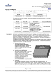
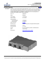
Description:
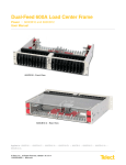
A DC-DC Converter Module Mounting Shelf designed to mount in a 19” or 23” (nominal) relay
rack or equipment mounting rack (configured for 19” mounting unless otherwise specified).
The Converter Module Mounting Shelf, when equipped with up to three separately ordered
Converter Modules (Spec. No. 486800127), provides a DC-DC Converter System that
operates from +24VDC to provide -48VDC load power.
Spec. No.:
584622000
Model:
DCS4830
Input Voltage:
+24 Volts DC
Output Voltage:
-48 Volts DC
Output Capacity:
Converter Module:
Mounting Shelf:
10 Amperes
30 Amperes
Agency Approval:
UL 1950
Mounting Type:
19” or 23” Relay Rack or Equipment Mounting Rack
Mounting Depth:
12.18”
Mounting Height
3.5” (2RU)
Access:
Front for Installation, Operation, and Maintenance
Color:
Textured Gray
Environment:
-20°C to +65°C (-4°F to +149°F).
Page 1 of 17
This document is property of Emerson Network Power, Energy Systems, North America, Inc. and contains confidential and proprietary information owned by Emerson Network Power, Energy
Systems, North America, Inc. Any copying, use, or disclosure of it without the written permission of Emerson Network Power, Energy Systems, North America, Inc. is strictly prohibited.
SAG584622000
Issue AB, November 18, 2009
System Application Guide
Spec. No. 584622000 (Model DCS4830)
TABLE OF CONTENTS
System Overview
Ordering
Information
Specifications
Physical Size
Information
Related
Documentation
SYSTEM OVERVIEW.................................................................................................................................................1
TABLE OF CONTENTS.............................................................................................................................................2
ORDERING INFORMATION......................................................................................................................................3
Converter Module Mounting Shelf (Model DCS4830) ......................................................................................3
Converter Modules (Model MHSA10B)..............................................................................................................3
Wiring Notes ........................................................................................................................................................4
DC Input (+24V) ...............................................................................................................................................4
DC Output (-48V) .............................................................................................................................................5
External Control and Alarms ............................................................................................................................6
Wiring Illustrations ..............................................................................................................................................7
DC Input (+24V) ...............................................................................................................................................7
DC Output (-48V) .............................................................................................................................................8
External Control and Alarms ............................................................................................................................9
SPECIFICATIONS....................................................................................................................................................10
1.1 Output Ratings...........................................................................................................................................10
1.2 Input Ratings..............................................................................................................................................11
1.3 Environmental Ratings .............................................................................................................................13
1.4 Standard Features .....................................................................................................................................13
PHYSICAL SIZE INFORMATION ............................................................................................................................15
Overall Dimensions ...........................................................................................................................................15
RELATED DOCUMENTATION................................................................................................................................16
Page 2 of 17
This document is property of Emerson Network Power, Energy Systems, North America, Inc. and contains confidential and proprietary information owned by Emerson Network Power, Energy
Systems, North America, Inc. Any copying, use, or disclosure of it without the written permission of Emerson Network Power, Energy Systems, North America, Inc. is strictly prohibited.
System Application Guide
Spec. No. 584622000 (Model DCS4830)
SAG584622000
Issue AB, November 18, 2009
Home
ORDERING INFORMATION
Converter Module Mounting Shelf (Model DCS4830)
Features
♦
The Converter Module Mounting Shelf accepts up to three (3) DC-DC Converter Modules.
♦
Two (2) blank panels are provided to cover unused Converter Module mounting positions.
♦
19” rack mounting angles factory installed,
23” rack mounting angles supplied loose
(can be adjusted for a 5” or 6” front projection).
Ordering Notes
1) For each DC-DC Converter System, specify (1) Spec. No. 584622000 Converter Module Mounting Shelf.
2) Also order one (1) to three (3) Converter Modules per Converter Module Mounting Shelf (as specified
next).
Converter Modules (Model MHSA10B)
Ordering Notes
1) Order one (1) to three (3) Spec. No. 486800127 DC-DC Converter Module for each Converter Module
Mounting Shelf ordered.
Page 3 of 17
This document is property of Emerson Network Power, Energy Systems, North America, Inc. and contains confidential and proprietary information owned by Emerson Network Power, Energy
Systems, North America, Inc. Any copying, use, or disclosure of it without the written permission of Emerson Network Power, Energy Systems, North America, Inc. is strictly prohibited.
SAG584622000
Issue AB, November 18, 2009
System Application Guide
Spec. No. 584622000 (Model DCS4830)
Home
Wiring Notes
Refer also to the next section, Wiring Illustrations.
DC Input (+24V)
Features
♦
Front accessed 1/4-20 x 5/8” studs on 5/8” centers are provided for installation of customer provided DC
input leads terminated in 2-hole lugs.
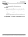
Ordering Notes
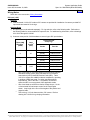
1) DC input lugs must be ordered separately. For lug selection, refer to the following table. Refer also to
the following table for recommended DC input wire size. For additional lug information, refer to drawings
031110100 through 031110300.
2) Customer must provide 1/4-20 hardware to secure lugs to DC input busbars.
Recm 90°C
1
Wire Size
(AWG)
4
2
1/0
1
2
3
Loop
Length 2
(feet)
47
74
118.9
Recommended
Crimp Lug 3
Vendor
Part No.
T&B
54206
Burndy
YA4CL-2TC14
Emerson
245346800
T&B
54207
Burndy
YA2CL-2TC14
Emerson
245346900
T&B
--
Burndy
YA25L-2TC14
Emerson
245391400
Wire sizes based on recommendations of the American National
Standards Institute (ANSI) approved National Fire Protection
Association's (NFPA) National Electrical Code (NEC). Table
310-16 for copper wire at 90°C conductor temperature, operating
in ambient of 30°C was used. For other operating ambient
temperatures, refer to the NEC. For operation in countries
where the NEC is not recognized, follow applicable codes.
Wire sizes listed are sufficient to restrict voltage drop to 1.0 volt
or less at rated full load output current for the loop lengths
shown. Loop length is the sum of the lengths of the positive and
negative leads.
Two-hole lug, 1/4" bolt clearance hole, 5/8" centers. Refer to
drawing 031110100 for lug crimping information.
Page 4 of 17
This document is property of Emerson Network Power, Energy Systems, North America, Inc. and contains confidential and proprietary information owned by Emerson Network Power, Energy
Systems, North America, Inc. Any copying, use, or disclosure of it without the written permission of Emerson Network Power, Energy Systems, North America, Inc. is strictly prohibited.
System Application Guide
Spec. No. 584622000 (Model DCS4830)
SAG584622000
Issue AB, November 18, 2009
Home
DC Output (-48V)
Features
♦
Two (2) 6-position 0A to 15A GMT Fuse Modules (for a total of 12 fuse positions) are provided for load
distribution.
♦
Load and load return leads are connected to a screw-type terminal block located on the front of each
GMT Fuse Module.
♦
Each GMT Fuse Module is equipped with six (6) dummy fuses and safety fuse covers.
Restrictions
The rating of the distribution device determines the wire size requirements. Refer to the American National
Standards Institute (ANSI) approved National Fire Protection Association's (NFPA) National Electrical Code
(NEC) and applicable local codes.
When used for power distribution, load should not exceed 80% of device rating, except 10 and 15 ampere
fuses, for which load should not exceed 70% of device rating.
Terminal block wire size capacity is 24 to 14 AWG.
Each GMT Fuse Module has a 30A @ +65°C (+149°F) maximum capacity (combined load of both GMT Fuse
Modules must not exceed shelf rating of 30A). Maximum GMT fuse size is 15A. Fuses are to be loaded from
bottom of the shelf to top of the shelf with highest value in the lowest position.
Caution: A fuse with a rating greater than 10 amperes SHALL HAVE an empty mounting position
between it and any other overcurrent protective device.
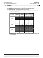
Ordering Notes
1) Order GMT fuses as required per the following table.
Ampere Rating
P/N
Fuse Color
18/100 GMT-A
1/4
1/2
3/4
1-1/3
2
3
5
7-1/2
10
15
Replacement
Dummy Fuse
Replacement Safety
Fuse Cover
248610301
248610200
248610300
248610500
248610700
248610800
248610900
248611000
248611300
248611200
248611500
-Violet
Red
Brown
White
Orange
Blue
Green
Black-White
Red-White
Red-Blue
248872600
---
102774
--
Page 5 of 17
This document is property of Emerson Network Power, Energy Systems, North America, Inc. and contains confidential and proprietary information owned by Emerson Network Power, Energy
Systems, North America, Inc. Any copying, use, or disclosure of it without the written permission of Emerson Network Power, Energy Systems, North America, Inc. is strictly prohibited.
SAG584622000
Issue AB, November 18, 2009
System Application Guide
Spec. No. 584622000 (Model DCS4830)
Home
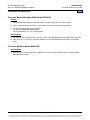
External Control and Alarms
Features
♦
An external control and alarm circuit card is located behind the shelf’s top front access panel. This circuit
card provides three sets of Form C relay contacts for external alarms, plus an ESTOP input. A terminal
block is provided on the circuit card for customer connections.
Restrictions
Terminal block wire size capacity is 14 to 26 AWG.
Relay contacts are rated for 1A at 30VDC or 0.3A at 60VDC.
Relays are energized for normal operating conditions and de-energized for an alarm condition.
Ordering Notes
1) Recommended Wire Size: 22 AWG for Loop Lengths Up to 200 ft.
18-20 AWG for Loop Lengths Over 200 ft.
Page 6 of 17
This document is property of Emerson Network Power, Energy Systems, North America, Inc. and contains confidential and proprietary information owned by Emerson Network Power, Energy
Systems, North America, Inc. Any copying, use, or disclosure of it without the written permission of Emerson Network Power, Energy Systems, North America, Inc. is strictly prohibited.
System Application Guide
Spec. No. 584622000 (Model DCS4830)
SAG584622000
Issue AB, November 18, 2009
Home
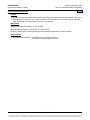
Wiring Illustrations
DC Input (+24V)
DC Input Terminals
Located Behind Insulating
Shield (bend shield up
to access terminals)
Front Cover
Captive Fasteners
DC Input Terminals
Top Cover (w/ insulating shield)
removed in illustration for clarity
only.
+24V RETURN
+24V
(1/4-20 x 5/8" Studs
on 5/8" Centers)
Page 7 of 17
This document is property of Emerson Network Power, Energy Systems, North America, Inc. and contains confidential and proprietary information owned by Emerson Network Power, Energy
Systems, North America, Inc. Any copying, use, or disclosure of it without the written permission of Emerson Network Power, Energy Systems, North America, Inc. is strictly prohibited.
SAG584622000
Issue AB, November 18, 2009
System Application Guide
Spec. No. 584622000 (Model DCS4830)
Home
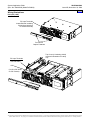
DC Output (-48V)
DC Output Leads Enter Here
Front Door Captive Fastener
Front View
DC Output
Terminal Blocks
-48V Distribution
Leads
Load Return
Leads
DC Output Terminal Blocks
Page 8 of 17
This document is property of Emerson Network Power, Energy Systems, North America, Inc. and contains confidential and proprietary information owned by Emerson Network Power, Energy
Systems, North America, Inc. Any copying, use, or disclosure of it without the written permission of Emerson Network Power, Energy Systems, North America, Inc. is strictly prohibited.
System Application Guide
Spec. No. 584622000 (Model DCS4830)
SAG584622000
Issue AB, November 18, 2009
Home
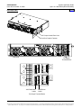
External Control and Alarms
Front Cover
Captive Fasteners
External Control and
Alarm Terminal Block
J1
All relay contacts are shown
in the deenergized state.
Relays are deenergized when
in the alarm state.
NC C
NO NC C
Minor
Alarm
Major
Alarm
NO NC C
NO
RTN ESTOP
(24V)
Fuse
Alarm
Page 9 of 17
This document is property of Emerson Network Power, Energy Systems, North America, Inc. and contains confidential and proprietary information owned by Emerson Network Power, Energy
Systems, North America, Inc. Any copying, use, or disclosure of it without the written permission of Emerson Network Power, Energy Systems, North America, Inc. is strictly prohibited.
System Application Guide
Spec. No. 584622000 (Model DCS4830)
SAG584622000
Issue AB, November 18, 2009
Home
SPECIFICATIONS
1.1
Output Ratings
1.1.1
Voltage: Nominal -48 volts DC, positive ground, non-adjustable.
1.1.2
Current: 10 amperes per DC-DC Converter Module, up to a total of 30 amperes per DC-DC
Converter Mounting Shelf when three (3) Converter Modules are installed.
1.1.3
Regulation
(A) Static: Steady state output voltage remains within ±1 volt of the pre-adjusted voltage for
any load current from no load to full load and over the specified input voltage range.
(B) Dynamic: For a step load change of 50% within the range of 10% to 100% of full rated
current, the maximum voltage transient will not exceed 5% of the initial steady state voltage.
1.1.4
Filtering: With at least 10% of rated full load on the output (-20°C to +65°C).
(A) Voice band noise is less than 32 dBrnC when measured with a noise meter using 600 ohm
bridged input and C-message weighting.
(B) Wide band noise does not exceed 250 millivolts peak to peak over the frequency range of 0
Hz to 20 MHz.
(C) Wide band noise does not exceed 30 millivolts rms over the frequency range of 0 Hz to 20
MHz (as measured with an HP3400A true rms voltmeter).
(D) Noise below –20°C is slightly higher.
1.1.5
Output Distribution: Two (2) 6-Position GMT Fuse Modules are provided for connecting DC
output load leads.
Page 10 of 17
This document is property of Emerson Network Power, Energy Systems, North America, Inc. and contains confidential and proprietary information owned by Emerson Network Power, Energy
Systems, North America, Inc. Any copying, use, or disclosure of it without the written permission of Emerson Network Power, Energy Systems, North America, Inc. is strictly prohibited.
System Application Guide
Spec. No. 584622000 (Model DCS4830)
SAG584622000
Issue AB, November 18, 2009
Home
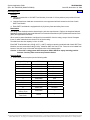
1.2
Input Ratings
1.2.1
Voltage: 24 volts DC nominal. Input voltage range is 21 to 28 volts DC.
1.2.2
Filtering: Noise reflected back to the central office battery is less than 32 dBrnC.
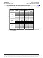
1.2.3
Typical Input Data - When equipped with one Converter Module.
(A) The output voltage of the DC-DC Converter Module is initially adjusted to 48 volts at 50%
load and 24 volts DC input.
Input Voltage
21 VDC
24 VDC
28 VDC
Percent
of Full Load
Input Current
(Amps)
Efficiency
(%)
Typical Heat
Dissipation
(BTU/Hr)
0
25
50
75
100
0
25
50
75
100
0
25
50
75
100
0.84
6.99
13.21
19.71
26.33
0.74
6.17
11.56
17.16
22.99
0.66
5.37
9.99
14.77
19.68
-82.1
86.5
86.6
86.0
-81.4
86.5
87.0
86.2
-80.2
85.8
86.7
86.3
60
90
128
190
264
61
94
128
183
260
63
102
136
188
257
(B) Maximum Current: Maximum input current is 26.33 amperes at full load (10 amperes) and
21 volts DC input.
Page 11 of 17
This document is property of Emerson Network Power, Energy Systems, North America, Inc. and contains confidential and proprietary information owned by Emerson Network Power, Energy
Systems, North America, Inc. Any copying, use, or disclosure of it without the written permission of Emerson Network Power, Energy Systems, North America, Inc. is strictly prohibited.
System Application Guide
Spec. No. 584622000 (Model DCS4830)
SAG584622000
Issue AB, November 18, 2009
Home
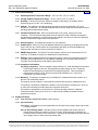
1.2.4
Typical Input Data - When equipped with three Converter Modules.
(A) The output voltage of the DC-DC Converter Modules are initially adjusted to 48 volts at 50%
load and 24 volts DC input.
Input Voltage
21 VDC
24 VDC
28 VDC
Percent
of Full Load
Input Current
(Amps)
Efficiency
(%)
Typical Heat
Dissipation
(BTU/Hr)
0
25
50
75
100
0
25
50
75
100
0
25
50
75
100
2.42
20.90
39.59
59.09
79.23
2.12
18.45
34.67
51.54
69.10
1.88
16.02
29.77
44.25
59.11
-82.3
86.4
86.4
85.4
-81.6
86.4
86.7
85.7
-80.5
86.2
86.5
85.9
173
265
385
575
828
174
278
387
562
810
180
298
392
569
799
(B) Maximum Current: Maximum input current is 79.23 amperes at full load (30 amperes) and
21 volts DC input.
Page 12 of 17
This document is property of Emerson Network Power, Energy Systems, North America, Inc. and contains confidential and proprietary information owned by Emerson Network Power, Energy
Systems, North America, Inc. Any copying, use, or disclosure of it without the written permission of Emerson Network Power, Energy Systems, North America, Inc. is strictly prohibited.
System Application Guide
Spec. No. 584622000 (Model DCS4830)
SAG584622000
Issue AB, November 18, 2009
Home
1.3
Environmental Ratings
1.3.1
Operating Ambient Temperature Range: -20°C to +65°C (-4°F to +149°F).
1.3.2
Storage Ambient Temperature Range: -40°C to +85°C (-40°F to +185°F).
1.3.3
Humidity: This DC-DC Converter System is capable of operating in an ambient relative
humidity range of 0 to 95%, non-condensing.
1.3.4
Altitude: The maximum operating ambient temperature should be derated by 10°C at an
elevation of 10,000 feet. For elevations between sea level and 10,000 feet, derate the maximum
operating ambient temperature linearly.
1.3.5
Ventilation Requirements: Each Converter Module is fan cooled, using front to back
ventilation. The Converter Mounting Shelf must be located such that ventilation openings are
not blocked and temperature of the air entering the cabinet is not above or below the Operating
Ambient Temperature Range stated in this document.
1.3.6
Heat Dissipation: 16.98 Watts per square foot / foot maximum.
1.3.7
Audible Noise: With three Converter Modules installed and operating, the audible noise at any
point 5 feet from any vertical surface of the equipment shelf does not exceed 60 dBA when
measured with a sound level meter conforming to ANSI S1.4.
1.3.8
EMI/RFI Suppression: This DC-DC Converter System conforms to the requirements of FCC
rules Part 15, Subpart B, Class B, for radiated and conducted noise.
1.3.9
Filtering: Noise reflected back to the central office battery is within the parameters set forth in
Telcordia Technical Reference TR-TSY-000009, paragraph 5.0, using test measurements in
Telcordia Technical Reference PUB 43802, pages 5 and 6.
1.3.10 Compliance Information:
(A) Safety Compliance: This unit meets the requirements of UL 1950, Standard for Information
Technology Equipment, and is UL Recognized as a power supply for use in Telephone,
Electronic Data Processing or Information Processing Equipment. This unit meets the
requirements of CSA 22.2, No. 950 and is tested and Certified by UL ("c UR") as a
Component Type Power Supply.
1.3.11 Mounting: This product is intended only for installation in a Restricted Access Location on or
above a non-combustible surface.
This product must be located in a Controlled Environment with access to Craftspersons only.
This product is intended for installation in Network Telecommunication Facilities (CO, vault, hut,
or other environmentally controlled electronic equipment enclosure).
This product is intended to be connected to the common bonding network in a Network
Telecommunication Facility (CO, vault, hut, or other environmentally controlled electronic
equipment enclosure).
1.4
Standard Features
1.4.1
Type of Power Conversion Circuit: High Frequency.
1.4.2
Input Protection:
(A) Fusing: A 35-ampere non-user replaceable fuse is located in the positive input lead of each
Converter Module.
(B) Low Input Voltage Inhibit: Operation of the Converter Modules will inhibit if the input
voltage drops to within the range of 19.25 to 20.5 volts. While operation is inhibited, the
Converter Shelf will draw no more than 20 mA. Operation will automatically resume after the
input voltage returns to within normal operating limits.
Page 13 of 17
This document is property of Emerson Network Power, Energy Systems, North America, Inc. and contains confidential and proprietary information owned by Emerson Network Power, Energy
Systems, North America, Inc. Any copying, use, or disclosure of it without the written permission of Emerson Network Power, Energy Systems, North America, Inc. is strictly prohibited.
System Application Guide
Spec. No. 584622000 (Model DCS4830)
SAG584622000
Issue AB, November 18, 2009
1.4.3
Home
Output Protection:
(A) Overvoltage Protection: Operation of a DC-DC Converter Module will automatically shut
down and lock out if the output voltage of the module exceeds 115% to 125% of the nominal
voltage. Manual restart is necessary after the overvoltage condition is corrected.
(B) Overcurrent Protection: When the output current of a DC-DC Converter Module increases
to a preset overcurrent value between 102.5% and 115% of rated full load, the output
voltage of the module will automatically decrease to limit current to this value. The output
will recover to within specified limits when the overload condition is removed.
(C) Over Temperature Protection: The operation of a DC-DC Converter Module will
automatically shut down if the internal temperature of the module exceeds a predetermined
value. Operation will automatically resume after the over-temperature condition is corrected.
1.4.4
Series Paralleling Output Diode: A series paralleling output diode is provided in each
Converter Module. This allows the Converter Modules to be paralleled for redundancy.
1.4.5
External Alarm Circuits: A set of Form-C relay contacts is provided for each of the following
alarms. Relays are energized for normal operating conditions and de-energized for an alarm
condition. Refer also to the Wiring Notes and Wiring Illustrations section in this document, and
to the DC-DC Converter System “Installation and User Instructions” (Section 6035) for wiring
information.
(A) Converter Minor Alarm: Alarms in the event of a failure in one or more Converter Modules.
Converter failure alarm conditions are as follows.
(1) Converter output increases above 52 volts DC or decreases below 44 volts DC for any
reason; including converter failure, high voltage shutdown, input voltage below 21 volts
DC (low input inhibit), or an overload condition.
(2) Cooling fan slows or stops due to fan failure or blocked rotor.
(B) Converter Major Alarm: Alarms in the event of a failure in more than one Converter
Module. Converter failure alarm conditions are as stated in (A) above.
(C) Fuse Alarm: Alarms if any GMT load fuse opens.
1.4.6
Remote Shutdown Input (ESTOP): The Converter Modules can be inhibited by applying an
external ground signal (24V Return). Converter Modules automatically restart upon removal of
the ground signal. Refer to the DC-DC Converter System “Installation and User Instructions”
(Section 6035) for wiring information.
1.4.7
Local Status and Alarm Indicators and Test Points: Refer to the DC-DC Converter System
“Installation and User Instructions” (Section 6035) for a complete description.
Location
Converter
Module
Converter
Module
Mounting
Shelf
NAME / Description
ON / STANDBY Switch
Type
Rocker Switch
OUTPUT OK
LED - Green
MAJOR
MINOR
INPUT OK
FUSE ALARM
LED - Red
LED - Yellow
LED - Green
LED - Red
SYSTEM CURRENT (+, -) (1A/mV)
Test Points
Page 14 of 17
This document is property of Emerson Network Power, Energy Systems, North America, Inc. and contains confidential and proprietary information owned by Emerson Network Power, Energy
Systems, North America, Inc. Any copying, use, or disclosure of it without the written permission of Emerson Network Power, Energy Systems, North America, Inc. is strictly prohibited.
System Application Guide
Spec. No. 584622000 (Model DCS4830)
SAG584622000
Issue AB, November 18, 2009
Home
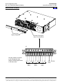
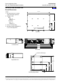
PHYSICAL SIZE INFORMATION
Overall Dimensions
17.37
Notes:
1. All dimensions are in inches,
unless otherwise specified.
2. Weight in LBS.
Shelf
Net: 17
Shipping: 21
Converter
Net: 3.2
Shipping: 5
3. Finish: Textured Gray.
4. Mounting angles adjustable for
5" or 6" front projection.
12.18
6.00
(note 4)
Top View
3.48
18.32
19.00
22.32
23.00
Left Side View
Front View
0.28 x 0.375 Slot (8)
Right Side View
3.47
3.23
1.98
1.48
Mounting Angle Detail
0.23
Page 15 of 17
This document is property of Emerson Network Power, Energy Systems, North America, Inc. and contains confidential and proprietary information owned by Emerson Network Power, Energy
Systems, North America, Inc. Any copying, use, or disclosure of it without the written permission of Emerson Network Power, Energy Systems, North America, Inc. is strictly prohibited.
System Application Guide
Spec. No. 584622000 (Model DCS4830)
SAG584622000
Issue AB, November 18, 2009
Home
RELATED DOCUMENTATION
Schematic Diagram:
Wiring Diagram:
Installation and User Instructions:
SD584622000
T584622000
Section 6035
Page 16 of 17
This document is property of Emerson Network Power, Energy Systems, North America, Inc. and contains confidential and proprietary information owned by Emerson Network Power, Energy
Systems, North America, Inc. Any copying, use, or disclosure of it without the written permission of Emerson Network Power, Energy Systems, North America, Inc. is strictly prohibited.
System Application Guide
Spec. No. 584622000 (Model DCS4830)
SAG584622000
Issue AB, November 18, 2009
Home
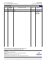
REVISION RECORD
Issue
Change
Number
(ECO)
AA
AB
LLP213133
LLP213431
Description of Change
New
Maximum heat dissipation value added.
Date
10/22/09
11/18/09
Approved
John Jasko
John Jasko
Joe Piwowar
Jan 22, 2010
John Jasko
Jan 25, 2010
Emerson Network Power, Energy Systems, North America, Inc.
1122 F Street / Lorain, Ohio 44052-2293 / (440) 288-1122
In Canada:
Emerson Network Power Canada
363 Sovereign Road / London, Ontario N6M 1A3 / 800-265-9243
In Mexico:
Emerson Network Power de Mexico, S.A. de C.V.
Apartado Postal 77001 / Mexico 10 D.F., MX 11200 / (52) 55-9140-6750
Page 17 of 17
This document is property of Emerson Network Power, Energy Systems, North America, Inc. and contains confidential and proprietary information owned by Emerson Network Power, Energy
Systems, North America, Inc. Any copying, use, or disclosure of it without the written permission of Emerson Network Power, Energy Systems, North America, Inc. is strictly prohibited.