1
Foundry NetIron
M2404C and M2404F
Metro Access Switches
Installation Guide
™
4980 Great America Parkway
Santa Clara, CA 95054
Tel 408.207.1700
www.foundrynetworks.com
January 2007
Copyright © 2007 Foundry Networks, Inc. All rights reserved.
No part of this work may be reproduced in any form or by any means – graphic, electronic or mechanical,
including photocopying, recording, taping or storage in an information retrieval system – without prior
written permission of the copyright owner.
The trademarks, logos and service marks ("Marks") displayed herein are the property of Foundry or other
third parties. You are not permitted to use these Marks without the prior written consent of Foundry or such
appropriate third party.
Foundry Networks, BigIron, FastIron, IronView, JetCore, NetIron, ServerIron, TurboIron, IronWare,
EdgeIron, IronPoint, the Iron family of marks and the Foundry Logo are trademarks or registered
trademarks of Foundry Networks, Inc. in the United States and other countries.
Foundry NetIron M2404C/M2404F Metro Access Switches
Safety Considerations
This equipment is for use in a restricted access area by qualified personnel only. To avoid
electric shock, do not perform any servicing other than those contained in the unpacking
instructions.
This equipment contains Electrostatic Discharge (ESD) sensitive components. Use ESD
protection before servicing or installing components of this system.
CAUTION Changes or modifications made to this device that are not expressly approved
by the party responsible for compliance could void the user’s authority to
operate the equipment.
CAUTION Remove the power cord from a power supply before you install it in or
remove it from the device. Otherwise, the power supply or the device could
be damaged as a result. (The device can be running while a power supply is
being installed or removed, but the power supply itself should not be
connected to a power source.)
CAUTION All devices with DC power supplies are intended for installation in restricted
access areas only. A restricted access area is where access can be gained only
by service personnel through the use of a special tool, lock and key, or other
means of security, and is controlled by the authority responsible for the
location.
WARNING
The equipment is designed to be used with Class 1 Laser fiber optic
transmitters which may endanger your eyes.
Do not look directly into the fiber optic cables or transmitter.
WARNING
HIGH VOLTAGE
Disconnect the product from the power line before removing the cover.
Any adjustment and maintenance of the opened device should be done
only while the device is disconnected from its source of power and should
only be performed by qualified personnel, authorized by Foundry
Networks.
January 2007
© 2007 Foundry Networks, Inc.
ii
Foundry NetIron M2404C/M2404F Metro Access Switches
WARNING
GROUNDING
Before connecting the product to the power line, make sure that the
protective ground terminal of the device is connected to the safety ground
conductor of the mains power cord.
The main power supply plug should only be inserted in a socket outlet
provided with a connected safety ground. The protective action must not
be negated by use of an extension cord (power cable) without a protective
conductor (grounding). Any interruption of the protective (grounding)
conductor or disconnection of the protective ground terminal can make
the device unsafe to use. Intentional interruption is prohibited.
This equipment has a connection between the earthed conductor of the
DC supply circuit and the grounding conductor.
WARNING
WIRING FOR NATIONAL POWER PLUG
A mains power cable according to National Electrical Code (NEC) with
molded IEC socket is supplied with each unit. The specific national
mains power plug should be wired as follows:
• Brown lead
Live (phase)
• Blue lead
Neutral
• Green/Yellow lead
Safety ground.
WARNING
LINE VOLTAGE
Before connecting the product to the power line, make sure the voltage
of the power source matches the requirements of the product, as marked
on the label located near the power connectors.
WARNING
DC POWER SOURCE
The DC power source should be protected with a branch circuit overcurrent protection rated at 10Amp, located in the building installation
January 2007
© 2007 Foundry Networks, Inc.
iii
Foundry NetIron M2404C/M2404F Metro Access Switches
Table of Contents
ABOUT THIS DOCUMENT......................................................................................... 1
WHO SHOULD USE THIS GUIDE ..................................................................................... 1
HOW THIS DOCUMENT IS ORGANIZED ........................................................................... 1
CONVENTIONS USED IN THIS DOCUMENT ...................................................................... 2
RELATED PUBLICATIONS ............................................................................................... 2
OVERVIEW ................................................................................................................... 3
INTRODUCTION .............................................................................................................. 3
HARDWARE DESCRIPTION ..................................................................................... 4
FRONT PANEL ................................................................................................................ 4
NetIron M2404C Front Panel Main Components .................................................... 5
NetIron M2404F Front Panel Main Components..................................................... 5
UNIT LEDS .................................................................................................................... 6
PORT STATUS LEDS ...................................................................................................... 7
NetIron M2404C Port Status LEDs .......................................................................... 7
NetIron M2404F Port Status LEDs........................................................................... 7
NetIron M2404F Dual-Mode Port Status LEDs ....................................................... 8
REAR PANEL – WITH AC POWER-SUPPLY UNITS ........................................................... 9
Panel Main Components ........................................................................................... 9
REAR PANEL – WITH DC POWER-SUPPLY UNITS .......................................................... 10
Panel Main Components ......................................................................................... 10
POWER SUPPLY UNITS ................................................................................................. 10
BLANK COVERS ........................................................................................................... 11
INSTALLATION AND SETUP .................................................................................. 13
PACKING LIST .............................................................................................................. 13
UNPACKING ................................................................................................................. 13
RACK MOUNTING ........................................................................................................ 13
Rack Mounting Specifications................................................................................. 14
ETHERNET CABLES ...................................................................................................... 15
CONSOLE INTERFACE ................................................................................................... 15
DC POWER INSTALLATION ........................................................................................... 15
GROUNDING THE SWITCH ............................................................................................ 16
LASER SAFETY ............................................................................................................. 17
INITIAL CONFIGURATION USING THE CONSOLE......................................... 18
INITIAL CONFIGURATION ............................................................................................. 18
SAVING CONFIGURATION IN A TEXT FILE .................................................................... 19
DOWNLOADING CONFIGURATION FROM BACKUP TEXT FILE ....................................... 20
RELOADING FACTORY DEFAULTS CONFIGURATION .................................................... 20
MONITORING/CONFIGURING CPU OPERATING TEMPERATURE .................................... 20
Temperature Management Commands ................................................................... 21
MONITORING THE POWER SUPPLIES STATUS ............................................................... 22
BUILT-IN SELF TEST (BIST) ................................................................................... 23
BIST TEST RESULTS REVIEW ...................................................................................... 23
STARTUP EXECUTION OF BIST .................................................................................... 24
SOFTWARE DOWNLOAD........................................................................................ 26
January 2007
© 2007 Foundry Networks, Inc.
iv
Foundry NetIron M2404C/M2404F Metro Access Switches
SOFTWARE IMAGE NAMING CONVENTIONS ................................................................. 26
DOWNLOADING A SOFTWARE IMAGE TO THE SWITCH USING TFTP ............................ 26
Preparing to Download an Image Using TFTP...................................................... 26
Downloading a Device Software Image Using TFTP............................................. 26
Downloading a NI-M2404WebView Image Using TFTP ....................................... 28
SOFTWARE UPGRADE VIA ETHERNET PORT (OUTBAND).............................................. 29
HOT-SWAPPING A POWER SUPPLY.................................................................... 30
SPECIFICATIONS ...................................................................................................... 31
PHYSICAL SPECIFICATIONS .......................................................................................... 31
Dimensions .............................................................................................................. 31
OPERATING CONDITIONS ............................................................................................. 31
MANAGEMENT FEATURES ............................................................................................ 32
SAFETY AND ELECTROMAGNETIC COMPATIBILITY ...................................................... 32
Safety ....................................................................................................................... 32
EMC ........................................................................................................................ 32
FCC 47 CFR: 2003 part 15 subpart B, class A ...................................................... 33
CISPR 22 CLASS A Warning .................................................................................. 33
VCCI (Japan) (Class A) .......................................................................................... 33
APPENDIX A: CAUTIONS AND WARNINGS ....................................................... 34
January 2007
© 2007 Foundry Networks, Inc.
v
Foundry NetIron M2404C/M2404F Metro Access Switches
About This Document
Who Should Use This Guide
The procedures in this manual are for trained and qualified service personnel who are proficient
with network switching and routing concepts. Installation, replacement and maintenance of the
equipment described in this guide may only be done by trained and qualified service personnel.
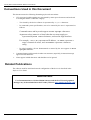
How This Document is Organized
This document contains the following chapters.
January 2007
Chapter
Contains
1. About This Document
The intended audience and the organization of this document,
the conventions used in this document, and reference to related
publications.
2. Overview
An introductory description of the platform, a list of the
product’s main features and a partial list of the management
options implemented by the device software image that is
installed on the platform.
3. Hardware Description
The front components, including traffic ports, management
ports and LEDs; The AC and DC power-supply options in the
rear panel; base-board components and the hot-swappable
power-supply units.
4. Installation and Setup
Packing list, instructions for unpacking, rack-mounting, desktop
installation, Ethernet cables, DC power installation safety
precautions, grounding, and Laser safety.
5. Initial Configuration
Using the Console
How to use the Command Line Interface (CLI) to configure the
platform and monitor its temperature, the power source status
and the status of the fans.
6. Built-In Self Test
(BIST)
Set of basic built in tests performed automatically at startup and
optionally by user’s request.
7. Software Download
How to upgrade the software via the network.
8. Hot-swapping
Modules
How to replace an access module or a redundant power-supply
unit without interrupting operation.
9. Specifications
Physical specifications, operating conditions and management
features.
© 2007 Foundry Networks, Inc.
1
Foundry NetIron M2404C/M2404F Metro Access Switches
Conventions Used in this Document
This document uses the following formatting styles and conventions:
•
CLI syntax and coded examples are represented by mono-space characters and enclosed
in rectangular frames. Under this category:
o
Text issued by the device software is represented by regular characters.
o
In command syntax specifications, text to be entered by the user is represented as
follows:
Command names and keywords appear as bold upright characters.
Argument values (numeric or literal) that the user must supply are
represented by bold italic characters, enclosed in angle-brackets.
For example: <a.b.c.d> represents an IP address, <0-4094> represents a
range of numerical values, and <filename> represents a character
string.
o
In coded examples, all text demonstrated as entered by the user appears in bold
upright characters.
•
Command names and keywords in other text structures (especially in instruction steps)
appear in bold characters.
•
Notes appear in bold characters and should never be ignored.
Related Publications
The software used for initial and network configuration of the device is described in the
Software User Guide.
IMPORTANT NOTE
User Documentation for NetIron M2404 Software and the Java™-based graphical
manager may be downloaded from the Foundry Website (www.foundrynetworks.com).
January 2007
© 2007 Foundry Networks, Inc.
2
Foundry NetIron M2404C/M2404F Metro Access Switches
Overview
Introduction
High powered networks require a combination of speed and robust services support to be able to
provide the intensive and fluctuating demands of their end users. To answer these requirements,
the network needs to provide data transmission at wire speed performance in a non-blocking
fashion. This switch is an enhanced Metro Ethernet CPE platform designed to provide wire
speed non-blocking Layer-2 and Layer-3 switching architecture as well as Hierarchical Virtual
Private LAN Services (HVPLS) hubs-and-spokes and MPLS based rings support.
The platform capabilities include Ethernet LAN/ Line services, use of advanced Hierarchical
QoS (tens of thousands of queues) as well as Hierarchical Virtual Private LAN Services
(HVPLS) hubs-and-spokes and MPLS based rings support. The platform offers services
convergence such as voice, data and video over Gigabit Ethernet, Enhanced Gigabit Ethernet
(MPLS/ VPLS).
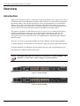
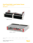
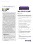
There are two flavors to the NetIron M2404, the NetIron M2404C and the NetIron M2404F.
(1) NetIron M2404C accommodates 24 Fast Ethernet copper ports and 4 Gigabit Ethernet ports;
(2) NetIron M2404F accommodates 24 Fast Ethernet fiber ports and 4 Gigabit Ethernet ports.
The platforms are identical in their performance.
NOTE
Throughout this guide, both switches are referred to as “NetIron M2404”, “the
platform” or “the switch”, unless relating to a specific platform.
Figure 1: NetIron M2404F
Figure 2: NetIron M2404C
January 2007
© 2007 Foundry Networks, Inc.
3
Foundry NetIron M2404C/M2404F Metro Access Switches
Hardware Description
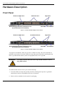
Front Panel
Enhanced GigE Ports
100baseX Ports
Switch Management Ports (Outband Port on
top and Console Port on bottom)
GigE Ports
PSU LEDs
Reset Button
Figure 3: NetIron M2404F Platform Front Panel
Enhanced GigE Ports
10/100baseTX Ports
Switch Management Ports (Outband Port on
top and Console Port on bottom)
GigE Ports
PSU LEDs
Reset Button
Figure 4: NetIron M2404C Platform Front Panel
To prepare for installation, make sure you have an ESD wrist strap that can be attached to a
grounded metal surface. Put on the ESD wrist strap and ground yourself by attaching the clip
end to a grounded metal surface (such as an equipment rack) to act as ground.
WARNING
For safety reasons, the ESD wrist strap should contain a series 1
meg ohm resistor.
To install an SFP transceiver into a port, do the following:
1. Put on the ESD wrist strap and ground yourself by attaching the clip end to a grounded
metal surface (such as an equipment rack) to act as ground.
2. Remove the new module from its protective packaging.
January 2007
© 2007 Foundry Networks, Inc.
4
Foundry NetIron M2404C/M2404F Metro Access Switches
3. Gently insert the SFP tranceiver into the port until the module clicks into place. The module
is keyed to prevent incorrect insertion. See Figure 5.
Important Note
When inserting an SFP tranceiver into ports marked 27 or 28, verify that the SFP is facing
upside -down (as shown in figure below). All other SFP ports on the switch face right-side up.
Figure 5: Inserting an SFP, upside-down, into the Enhanced GigE Slot
NetIron M2404C Front Panel Main Components
Component
Description
For NetIron M2404C:
10/100baseTX Ports
24 RJ-45 sockets with 10/100 Mbps LAN speed auto sensing,
marked 1 to 24.
GigE Dual-Mode Ports
Two dual-mode1000baseX interface (SFP) or 10/100/1000BaseT
(RJ45) marked 25 and 26.
Enhanced GigE Ports
Two 1000baseX interface (SFP) marked 27 and 28. Please note
that the SFP transceivers are inserted into the slot, belly-down, as
shown in figure above.
Console Management
Port
RJ45 socket for CLI configuration and management of the unit.
Ethernet Management
Port
RJ45 socket with 10/100 Mbps LAN speed auto sensing for outof-band Ethernet management and software update.
RST Button
Reset button. To avoid accidental activation, the button is recessed
behind the panel. Press with a pin or a similar narrow object.
NetIron M2404F Front Panel Main Components
January 2007
Component
Description
For NetIron M2404F:
100baseX Ports
24 SFP sockets marked 1 to 24.
© 2007 Foundry Networks, Inc.
5
Foundry NetIron M2404C/M2404F Metro Access Switches
Component
Description
GigE Dual-Mode Ports
Two dual-mode1000baseX interface (SFP) or 10/100/1000BaseT
(RJ45) marked 25 and 26.
Enhanced GigE Ports
Two 1000baseX interface (SFP) marked 27 and 28. Please note
that the SFP transceivers are inserted into the slot, belly-down, as
shown in figure above.
Console Management
Port
RJ45 socket for CLI configuration and management of the unit.
Ethernet Management
Port
RJ45 socket with 10/100 Mbps LAN speed auto sensing for outof-band Ethernet management and software update.
RST Button
Reset button. To avoid accidental activation, the button is recessed
behind the panel. Press with a pin or a similar narrow object.
Unit LEDs
The following descibes the LEDs on the chassis.
Label
Function
ETH
Ethernet management interface
status.
FLT
MNG
STS
PSU #1
PSU #2
January 2007
Indication
Platform HW fault.
CPU controller is processing
management tasks.
General platform status.
PSU #1 status.
PSU #2 status.
•
Off – Link down.
•
Green – Link up.
•
Blinking green – activity.
•
Off – Switch hardware OK.
•
Red – CPU can't boot.
•
Blinking red – Failure during BIST.
•
Off – No management activity.
•
Green – Management activity.
•
Off – Platform processing boot loader.
•
Green fast blink – Platform initializing
application.
•
Green – Normal operation.
•
Green – PS #1 functioning.
•
Red – Problem in PS #1 or no power
feed.
•
Off – PS #1 removed.
•
Green – PS #2 functioning.
•
Red – Problem in PS #2 or no power
feed.
•
Off – PS #2 removed.
© 2007 Foundry Networks, Inc.
6
Foundry NetIron M2404C/M2404F Metro Access Switches
Port Status LEDs
A status LED is associated with each port.
Port Status
Indication
Link
Green
Activity
Blinking green
Fault/disabled
Amber
NetIron M2404C Port Status LEDs
Port 1
Port 3
Port 5
Port 7
Port 9
Port 2
Port 4
Port 6
Port 8
Port 10 Port 12
Port 11
Figure 6: Location of NetIron M2404C Port Status LEDs
The port status LEDs (1 to 24) for NetIron M2404C are situated on the upper row of ports. The
LED on the left side of each upper port is associated with that port. The LED on the right side of
each upper port is associated with the port underneath that port.
NetIron M2404F Port Status LEDs
Port 23
Port 13
Port 15
Port 17 Port 19 Port 21
Port 14
Port 16
Port 18 Port 20 Port 22 Port 24
Figure 7: Location of NetIron M2404C Port Status LEDs
The port status LEDs (1 to 24) for NetIron M2404F are situated below each SFP.
January 2007
© 2007 Foundry Networks, Inc.
7
Foundry NetIron M2404C/M2404F Metro Access Switches
NetIron M2404F Dual-Mode Port Status LEDs
Figure 8: Location of NetIron M2404F Dual-Mode Port Status LEDs
Dual-mode port status LEDs are associated with dual-mode RJ45/SFP GiGE ports 25 and 26.
RJ-45 Indicators
RJ45 Dual-Mode Port Status
Indication
Link/Activity
Left LED is Green
Disabled
Right LED is Amber
SFP Indicators
January 2007
SFP Dual-Mode Port Status
Indication
Link
Green
Activity
Blinking green
Disabled
Amber
© 2007 Foundry Networks, Inc.
8
Foundry NetIron M2404C/M2404F Metro Access Switches
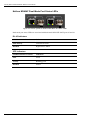
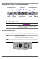
Rear Panel – with AC Power-Supply Units
Hot-swappable PSU #2
On-off
switch
Fan apertures
AC-Power
inlet
Grounding studs
Hot-swappable PSU #1
On-off
switch
AC-Power
inlet
Figure 9: Rear Pane l with AC PSUs
Panel Main Components
January 2007
Two AC Power supplies
As specified in Power Supply Units.
Two grounding posts
Designed for a UL-listed two-hole long-barrel 5/8 10
AWG compression lug. Burndy YAZV10-2TC14 or an
equivalent is recommended.
© 2007 Foundry Networks, Inc.
9
Foundry NetIron M2404C/M2404F Metro Access Switches
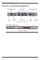
Rear Panel – with DC Power-supply Units
Hot-swappable PSU #2
Terminal
block
Fan apertures
PWR and
Invert. Con.
LEDs
Grounding studs
Hot-swappable PSU #1
Terminal
block
PWR and
Invert. Con.
LEDs
Figure 10: Rear Panel with DC PSUs
Panel Main Components
Two DC Power supplies
As specified in Power Supply Units.
Two grounding posts
Designed for a UL-listed two-hole long-barrel 5/8 10
AWG compression lug. Burndy YAZV10-2TC14 or an
equivalent is recommended.
Power Supply Units
Power is fed to the platform via two redundant hot-swappable power supply units (PSUs). The
following PSU versions are available:
ACPS
Dual-range AC power supply:
100-120 VAC@ 5A or 200-240VAC@ 2.5A 50/60 Hz
DCPS
DC power supply:
-48VDC Nominal @ 3A (minimum: -36V ; maximum -72VDC)
Figure 11: AC Power Supply Unit
January 2007
© 2007 Foundry Networks, Inc.
10
Foundry NetIron M2404C/M2404F Metro Access Switches
DC power-supply terminals:
LEDs:
-48V/3A GND +BAT.RET
INVERT CON.
PWR
Figure 12: DC Power Supply Unit
The DC power supply panel has the following components:
Input terminals:
-48V/3A
Negative DC input terminal
GND
Ground terminal internally connected to the platform’s ground line
+BAT.RET
Positive DC input terminal
NOTE
Neither the +BAT.RET nor the -48VDC is connected to the GND terminal. If
required, this can be performed externally by the user.
LEDs:
PWR
Glows green when power is on
INVERT CON.
Glows red to indicate inverted DC polarity
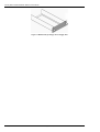
Blank Covers
To avoid overheating of the components by improper air-flow, always keep empty slots
covered. Use the panel screws on the supplied blank faceplates and blank filler to fasten the
blanks to the appropriate empty slots.
January 2007
© 2007 Foundry Networks, Inc.
11
Foundry NetIron M2404C/M2404F Metro Access Switches
Figure 13 Blank Filler for Empty Power-Supply Slot
January 2007
© 2007 Foundry Networks, Inc.
12
Foundry NetIron M2404C/M2404F Metro Access Switches
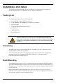
Installation and Setup
This section provides installation and setup instructions. The platform can be installed in a
standard 19-inch rack or as a standalone unit in a desktop configuration.
Packing List
The shipping package includes the following items:
•
NetIron M2404F /NetIron M2404C platform.
•
One AC (ACPS) or DC (DCPS) power-supply unit, installed.
•
One power cable.
•
Two rack-mounting brackets with screws
•
Console cable
•
1 Blank PSU filler
•
Documentation CD
WARNING
If the installation requires a power cord other than the one supplied with
the device, make sure you use a power cord displaying the mark of the
safety agency that defines the regulations for power cords in your country.
The mark is your assurance that the power cord can be used safely with
the device.
Unpacking
The platform is factory tested and inspected prior to shipment. In case of damage to the unit
during shipment, contact your local dealer.
It is recommended that you keep the shipping package until the unit has been installed and
verified as operational. The platform, like all electronic devices with static sensitive
components, should be handled with care.
Rack Mounting
The supplied mounting brackets can be attached to the sides of the chassis either flush with the
front panel (flush-mounting) or midway between the front and rear panels (mid-mounting). Use
the supplied screws to fasten the mounting brackets to the chassis in the required position (flush
or mid-mounting).
Before mounting any equipment onto the rack, make sure that there is generous clearance
behind the rack for proper ventilation and for easy access to the rear components. Do not place
objects that might obstruct airflow behind the chassis.
January 2007
© 2007 Foundry Networks, Inc.
13
Foundry NetIron M2404C/M2404F Metro Access Switches
WARNING
Make sure the rack or cabinet housing the device is adequately secured
to prevent it from becoming unstable or falling over.
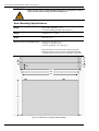
Rack Mounting Specifications
Width
Basic body: 440 mm (17.4”)
Overall, including brackets: 483 mm (19”)
Height
44 mm (1.73”) = 1 RU
Depth
414 mm (16.3”)
Distance between mounting holes
Horizontal: 465 mm (18.3”)
Vertical: 31.75 mm (1.25”)
Vertical separation: 12.7 mm (0.5”)
Note that there is no need to leave vertical spacing
between units on a rack, as heat is dissipated through
ventilation holes in the front, rear and sides of the unit.
44
12.7
31.75
15.875
483
465
440
414
Figure 14: Dimensions in mm for Rack-mounting
January 2007
© 2007 Foundry Networks, Inc.
14
Foundry NetIron M2404C/M2404F Metro Access Switches
Ethernet Cables
When connecting an RJ-45/RJ-48 port to an end station, workstation or server, use a standard
RJ-45/RJ-48 pin-out cable.
Console Interface
A simple menu-driven interface provides for system initialization and diagnostics. The Console
interface is EIA232 VT-100 compatible. The primary purpose of the terminal interface is to set
basic operational parameters.
The terminal interface is password protected. By default there is no password set for the
terminal interface.
Using the enclosed serial cable (see table below for wiring), connect the RJ-45 connector to the
connector marked “Console” and the other side to the 9-pin serial port connector on the back of
your PC.
The supplied cable has the following pinout:
NOTE
Switch Side
PC Side
RJ-45 Pin #
DB-9 Female
3
2
2
3
5
5
You can also use a RJ-45/DB-9 cable.
DC Power installation
The DC supply source is to be located within the same premises as this equipment. The DC
power source should be protected with a circuit breaker with a rating of 10Amp as disconnect
device, connected to the non-grounding conductor. The unit shall be connected directly to the
DC supply system; there shall be no switching or disconnecting devices in the earthed circuit
conductor between the DC source and the point of connection of the grounding electrode
conductor.
This equipment shall be located in the same immediate area (such as, adjacent cabinets) as any
other equipment that has a connection between the earthed conductor of the same DC supply
circuit and the grounding conductor, and also the point of grounding of the DC system. The DC
system shall not be earthed elsewhere.
January 2007
© 2007 Foundry Networks, Inc.
15
Foundry NetIron M2404C/M2404F Metro Access Switches
For each DC power block a set of a minimum 2x18AWG cables shall be used with suitable end
terminal legs matching the conductor’s gauge. Use a RED lead to for the positive conductor and
a BLACK lead for the negative conductor. It is recommended that only UL listed components
be used for the DC power connections.
CAUTION For a DC system, use a grounding wire of at least 10 American Wire
Gauge (AWG). The 10 AWG wire should be attached to an agencyapproved crimp connector, crimped with the proper tool. The crimp
connector should allow for securement to both ground screws on the
enclosure.
CAUTION For the DC input circuit to the system, make sure there is a Listed 10 amp
circuit, minimum -48Vdc, double pole, on the input to the terminal block.
The input wiring for connection to the product should be Listed copper
wire, 18 AWG, marked VW-1, and rated minimum 90 deg. C.
NOTE
There is no connection needed for GND. Only the ground wire is connected to
the Grounding Stud.
Grounding the Switch
WARNING
Before connecting power to the switch, make sure that both grounding
posts in the rear panel are firmly connected to a reliable ground through a
#10 AWG grounding wire terminated by a UL-listed two-hole long-barrel
5/8 10 AWG compression lug with hole size and spacing as shown in Figure
15 below.
The Burndy YAZV10-2TC14 or an equivalent UL-listed two-hole
compression lug is recommended.
16 mm
(5/8”)
φ6.4 mm
10 AWG
(1/4”)
Figure 15: Compression Grounding Lug
To connect the switch to the ground, proceed as follows:
1.
January 2007
Prepare a minimum #10 AWG grounding wire terminated by a crimped two-hole lug
with hole diameter and spacing as shown in Figure 15. Use a suitable crimping tool to
fasten the lug securely to the wire. Adhere to your company’s policy as to the wire gauge
and the number of crimps on the lug.
© 2007 Foundry Networks, Inc.
16
Foundry NetIron M2404C/M2404F Metro Access Switches
2.
Remove the bolts and spring-washers from the grounding posts on the switch’s rear
panel, and clean the metal surface underneath with a dry cloth if necessary.
3.
Apply some anti-oxidant onto the metal surface.
4.
Mount the lug on the two grounding posts, replace the spring-washers and fasten the
bolts. Avoid using excessive torque.
5.
Connect the grounding wire to a reliable ground. If the switch is mounted in a rack, use a
common ground for all devices on the rack, according to your company’s policy.
Laser Safety
The device is provided with SFP sockets in which fiber optic transceivers may be installed. In
order to meet the safety requirement of Class 1 fiber optic laser emission levels, only fiber optic
transceivers which comply with IEC 60825-1 or IEC 60825-2 and FDA 21 CFR 1040.10 and
CFR 1040.1 must be used.
January 2007
© 2007 Foundry Networks, Inc.
17
Foundry NetIron M2404C/M2404F Metro Access Switches
Initial Configuration Using the Console
Initial Configuration
The Configuration command-language interface (CLI) is accessed by using a VT-100 (or
compatible terminal) to the console port of the switch. The terminal port parameters are fixed at:
9600 bps, 8 data bits, 1 stop bit, no parity and without flow control. This provides a convenient
method for initial setup of the switch. System parameters are stored in a non-volatile memory.
They need to be set up only during the initial setup or when the system has been reset to the
factory defaults.
The following keys are used to access the menu:
Enter
Ends an input line
Backspace
Clears last character in input mode
Tab
Auto-Completes a command
A screen similar to the following example appears on the Console Port at power up or reset:
////////////////////////////////////////////////////////////////////
//
// Foundry Networks
//
// Switch model
: NETIRON M2404F
// SW version
: 2.0.00 created January 12 2007 - 21:35:37
//
//
//
///////////////////////////////////////////////////////////////////
User Access Verification
Password:
There is no default password, press <Enter> for password.
NOTE
You can configure the password later.
Type ? to display the available commands:
device-name>?
alias
An alias of a command
dir
List files in flash.
display
Display file.
enable
Turn on privileged mode command
exit
Exit current mode and down to previous mode
help
Description of the interactive help system
ls
List files in flash.
no
Negate a command or set to defaults
January 2007
© 2007 Foundry Networks, Inc.
18
Foundry NetIron M2404C/M2404F Metro Access Switches
quit
show
terminal
who
Disconnect and logout
Show running system information
Terminal configuration setup
Display who is on vty
To continue initial configuration procedure perform the following steps:
1.
Enter privileged (Enable) mode. Type the command: enable.
2.
Enter configure mode. Type the command: configure terminal.
3.
Set the switch IP address: Type the command: ip address <aa.bb.cc.dd/yy>, where
<aa.bb.cc.dd> is the IP address assigned to the switch and yy is the number of bits in
the netmask (e.g. netmask of 255.255.255.0 would be /24).
4.
Set the default gateway IP address if the host is on a different subnet: Type the
command: ip route 0.0.0.0/0 <aa.bb.cc.dd> where <aa.bb.cc.dd> is the IP address
of the default gateway.
5.
Return to privileged (Enable) mode: Type the command: end.
6.
To verify if the IP addresses were set correctly, type: show ip.
Example:
device-name#show ip
IP-ADDR : 100.100.100.1 NET-MASK : 255.255.255.0
NOTE
7.
The show command can be used to display a variety of parameters: Setup
Configuration and others. To view the show command options type: show ?
Type the command: write from privileged (Enable) mode.
At this point the Initial configuration setup is completed and the switch can be accessed using
Ping or Telnet commands.
Saving Configuration in a Text File
A variety of TFTP Server programs can be used by the host computer where the software
images and configuration files are located. The only information that is required by the TFTP
Server is the location of the file on the host computer’s file system.
It is recommended that the configuration be saved in an external text backup file. To write the
backup configuration file, use the command copy.
To view the copy command options type: copy ?
device-name#copy ?
FILE-NAME
Source file. Format: [[device/]path]file-name
device: flash: - local file system
tftp://A.B.C.D - TFTP server
Example: tftp://1.1.1.1/directory/filename.bin
January 2007
© 2007 Foundry Networks, Inc.
19
Foundry NetIron M2404C/M2404F Metro Access Switches
application
java
running-config
startup-config
Application downloading image
Java downloading image
Copy running config...
Startup configuration data
To write the backup configuration file, type:
device-name#copy startup-config <IP address> <filename>
<filename> is the file where the configuration file was saved.
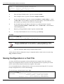
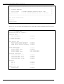
Downloading Configuration from Backup Text File
The configuration file can be easily downloaded, using the copy command. Type:
copy tftp://<Server IP address>/<filename> startup-config
<filename> is the file where the configuration file was saved.
NOTE
The copy command uses TFTP protocol for its execution, so prior to using the
copy command, verify that the TFTP Server program is executed by the
addressed computer.
Reloading Factory Defaults Configuration
Use the reload command to reload the factory defaults configuration.
device-name#reload to-defaults
Restore factory setting and Reboot the Switch !
[y/n]: y
Rebooting ...
NOTE
The reload to-defaults command does NOT change the IP address and netmask
of the switch.
Monitoring/Configuring CPU Operating Temperature
Should the temperature reach the configured upper limit, the unit will send an SNMP trap to the
management station. If this occurs, the user is requested to make sure that all unit ventilation
airways are free and disengaged and that the fans are functioning.
January 2007
© 2007 Foundry Networks, Inc.
20
Foundry NetIron M2404C/M2404F Metro Access Switches
Temperature Management Commands
Viewing the Status:
device-name#show temperature
CPU Temperature = 28C / 82F
device-name#show temperature high-limit
CPU Temperature high limit = 20C / 68F
Configuring Temperature Management Parameters:
device-name#configure terminal
device-name(config)#monitor temperature
device-name(config monitor temperature C)#limit
NUMBER Value of limit for alerting current test
device-name(config monitor temperature C)#limit 70
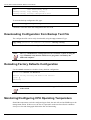
Viewing the Temperature Setting from a Running Configuration:
device-name#show running-config
Building the configuration ...
! Current Configuration:
!
! Version 2.0
!
password a1FhfHKwXHFlU
ip address 10.4.1.5 255.255.0.0
!
! Switch Monitoring configuration:
!
monitor temperature
enable
limit 70
!
Restoring the Default Value:
device-name#configure terminal
device-name(config)#monitor temperature
device-name(config monitor temperature C)#default
January 2007
© 2007 Foundry Networks, Inc.
21
Foundry NetIron M2404C/M2404F Metro Access Switches
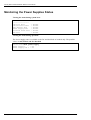
Monitoring the Power Supplies Status
Viewing the status during system boot:
BUILT-IN SELF TEST
-----------------CPU Core Test
CPU Interface Test
Data Buffer Test
Power Supply Test
On-board Power Test
Fan Test
:
:
:
:
:
:
Passed
Passed
Passed
Passed
Passed
Passed
Viewing the status during operation:
The Power Supply status is available on the DC and dual-feed AC models only. The possible
values are OK, Failed, and Not Installed.
device-name#show power-supply
Power supply 1
: OK
Power supply fan 1 : OK
January 2007
© 2007 Foundry Networks, Inc.
22
Foundry NetIron M2404C/M2404F Metro Access Switches
Built-In Self Test (BIST)
The BIST performs a set of basic hardware and configuration validity tests. Tests in the BIST
are sorted into several groups – for example, the tests of the Power Supply units belong to a
Power Supply Test group.
Startup BIST - The BIST is performed automatically on startup. The results are summarized on
the terminal before the switch banner.
BIST by request - A user may request BIST execution at any time by using a CLI command.
The current BIST status may be read and cleared by using CLI commands. When the BIST
detects a failure in any of the tests, it causes the Status LED indicator to blink.
The switch supports the following tests:
• CPU Core Test
• CPU Interface Test
• Data Buffer Test
• Power Supply Test
• On-Board Power Test
• Fan Test
• Temperature Test.
Table 1 describes the tests.
Table 1: Description of the Built-in Tests
Test
Description
CPU Core Test
Checks CPU block integrity
CPU Interface Test
Checks the existence of the UART (register write/read operation).
Both COM1 and COM2 are checked.
Data Buffer Test
Checks the integrity of NVRAM database.
Power Supply Test
Checks the existence and status of the DC power supplies.
If both DC power supplies are connected, the test will result with
Passed. When one of the DC power supply is disconnected, the test
will result with Failed.
Fan Test
Checks the status of the 3 fans.
On-Board Power Test
Checks the 5 On-Board Power levels: 3.2V, 2.5V, 1.8V, 1.5V and
1.25V.
Temperature Test
Validates temperature ranges inside the device and tests temperature
sensors.
BIST Test Results Review
If any of the BIST tests fail, the FLT LED starts blinking. To display BIST results, perform the
following steps:
1. Connect a terminal cable to Console port.
January 2007
© 2007 Foundry Networks, Inc.
23
Foundry NetIron M2404C/M2404F Metro Access Switches
2. Re-power the unit, if required.
3. Use the show self-test command in Privileged (Enable) mode. If you prefer to display all
BIST results, use the show self-test full command instead.
To invoke a BIST by Request at any time while the switch is running, use the self-test
command in Privileged (Enable) mode.
The switch will automatically start up in debug mode when one of the five On-Board power
levels deviates by 2% above or below the required level. See the explanation below.
Startup Execution of BIST
The startup BIST reports a summary of the results by BIST group. If all tests of the group pass,
Passed is displayed for all groups.
Press any key to stop auto-boot...
0
auto-booting...
Uncompressing 4329228 bytes...
Loading image... 17671392
Init TFFS
BUILT-IN SELF TEST
-----------------CPU Core Test
CPU Interface Test
Data Buffer Test
Power Supply Test
On-board Power Test
Fan Test
:
:
:
:
:
:
Passed
Passed
Passed
Passed
Passed
Passed
If any test in the group except the On-Board Power fails, Failed is displayed for the entire group
and the switch starts normally. In such cases, the switch starts in debug mode (switching
disabled and the switch is running with the default configuration). If one of the On-Board Power
level checks fails, the switch will not initialize the ports and will start in a special debug mode,
as shown below:
Press any key to stop auto-boot...
0
auto-booting...
Uncompressing 4329228 bytes...
Loading image... 17671392
Init TFFS
BUILT-IN SELF TEST
-----------------CPU Core Test
CPU Interface Test
Data Buffer Test
Power Supply Test
On-board Power Test
Fan Test
January 2007
:
:
:
:
:
:
Passed
Passed
Passed
Passed
Passed
Passed
© 2007 Foundry Networks, Inc.
24
Foundry NetIron M2404C/M2404F Metro Access Switches
////////////////////////////////////////////////////////////////////
//................................................................//
// FOUNDRY NETWORKS
//
//
//
// Switch model
: FOUNDRY NETWORKS NETIRON M2404F 256M
//
// SW version
: 2.0.00 created January 15 2007 - 21:35:37
//
//
//
////////////////////////////////////////////////////////////////////
User Access Verification
Password:
device-name>
In this case, you can enter into Enable mode as usual, and examine the detailed Self-Test results.
For example:
device-name#self-test
Processing BIST by request...
CPU Core Test
CPU Validation
:
CPU Interface Test
UART Existence
:
- Passed
- Passed
Data Buffer Test
:
Application Image Validity - Passed
Java Agent Image Validity
- Passed
PROM Device Access Validity - Passed
January 2007
Power Supply Test
:
Power Supply 1
Power Supply Fan 1
Power Supply 2
Power Supply Fan 2
-
Passed
Passed
Not installed
Not installed
On-board Power Test :
On-board Power 3.3V
On-board Power 2.5V
On-board Power 1.8V
On-board Power 1.25V
-
Passed
Passed
Passed
Passed
Fan Test
Fan 1
Fan 2
Fan 3
:
- Passed
- Passed
- Passed
Temperature Test
Temperature
:
- Passed
© 2007 Foundry Networks, Inc.
25
Foundry NetIron M2404C/M2404F Metro Access Switches
Software Download
The executable software image contained on the platform can be upgraded via the network
whenever new versions become available, reflecting changes in the MIBs or enhancements to
the software. The software is stored in erasable Flash memory. It must be downloaded using the
Trivial File Transfer Protocol (TFTP).
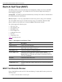
Software Image Naming Conventions
Table 2 displays an example of typical software image names.
NOTE The image name is a typical example. The numbers in the name are illustrative
and should not be regarded as the latest released version numbers.
Table 2: Typical Software Image Filename Example
Typical Application Image Name
Typical NI-M2404WebView Image Name
NetIron 2404 v2.0.00.bin
NI-M2404WebViewL3-V3.6.8.img
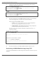
Downloading a Software Image to the Switch Using
TFTP
Preparing to Download an Image Using TFTP
Before you begin to download a software image using TFTP, take the following precautions:
•
Ensure that the workstation acting as TFTP server is configured properly.
•
Ensure that the switch has a route to the TFTP server. The switch and the TFTP server must
be in the same subnet if you do not have a router to route traffic between subnets. Use the
ping command to check connectivity to the TFTP server.
•
Ensure that the software image to be downloaded is in the correct directory on the TFTP
server.
•
Ensure that the permissions on the file are set correctly. Permissions on the file should be at
least read for the specific username.
•
A power outage (or other problem) during the download procedure can corrupt the Flash
code. If the Flash code is corrupted, you can connect to the switch through the console port
and download the application in the Loader by using the download application command.
Downloading a Device Software Image Using TFTP
To download a device software image to the switch from a TFTP server, proceed as follows:
January 2007
© 2007 Foundry Networks, Inc.
26
Foundry NetIron M2404C/M2404F Metro Access Switches
1.
Copy the device software image file to the appropriate TFTP directory on the
workstation.
2.
Log into the switch through the console port or through a Telnet session. If you log in
using Telnet, your Telnet session will disconnect when you reset the switch to run the
new software.
3.
Make sure there is enough free space on the device file system. Use “dir” command
for this. Free disk space should be at least 0.5MB larger then the downloaded
application size.
Example:
device-name#dir
Listing Directory flash:/:
d S
2048 Jun 30 2005
d S
2048 Jan 1 1993
d S
2048 Jun 14 2005
d S
2048 Jan 1 1980
d S
2048 Jul 5 2005
d SH
2048 Jan 1 1980
260 Jan 1 1993
43796 Jul 5 2005
5382 Jul 5 2005
17:56
00:04
12:01
00:00
21:36
00:00
00:00
21:26
21:26
Boot/
Etc/
Java/
Log/
Usr/
Hidden/
profile.cfg
dflt_startup_bin.cfg
dflt_startup.cfg
Free disk space 5655104
4.
If there is not enough free space, delete unnecessary files. This is done by using “del”
command.
device-name#del <filename>
Example:
device-name#del /Boot/Oldimage.bin
5.
Download the device software image from the TFTP server using the copy
application command in Privileged (Enable) mode:
device-name#copy application <TFTP URL> [<destination file name>]
Example:
device-name#copy application tftp://192.192.54.10/M2404Cv2.0.bin
NOTE The switch remains operational while the image is downloaded.
The application is downloaded into /Boot directory.
January 2007
© 2007 Foundry Networks, Inc.
27
Foundry NetIron M2404C/M2404F Metro Access Switches
6.
Configure the switch to boot with the newly downloaded image. This is done by
selecting boot application and boot device.
device-name#config boot-param
device-name(boot param)#application <local application filename>
device-name(boot param)#device local
device-name(boot param)#exit
Example:
device-name#config boot
device-name(boot param)#application M2404v2.0.bin
device-name(boot param)#device local
device-name(boot param)#exit
7.
Reset the switch using one of the reload commands. Note that, if you are connected
to the switch through Telnet, your Telnet session will be disconnected.
Select from the following reload commands:
1. reload save - this command updates the device's startup configuration to
match the running configuration and reboots the switch.
2. reload to-defaults – this command resets the device's startup configuration
to match the factory defaults and reboots the switch.
After the execution of the command, confirmation is required [y/n]. Enter “y” to
confirm the command.
Example with “reload” command:
device-name#reload save
Save current configuration and reboot the Switch ?
[y/n] : y
...
Example with “reload to-defaults” command:
device-name#reload to-defaults
Restore factory setting and reboot the Switch ?
[y/n] : y
...
8.
After the switch reboots, use the show version command to check the version.
Downloading a NI-M2404WebView Image Using TFTP
To download a NI-M2404WebView software image to the switch from a TFTP server, proceed
as follows:
January 2007
© 2007 Foundry Networks, Inc.
28
Foundry NetIron M2404C/M2404F Metro Access Switches
1.
Copy the software image file to the appropriate TFTP directory on the workstation.
2.
Log into the switch through the console port or through a Telnet session.
3.
Download the software image from the TFTP server using the copy java command
in Privileged (Enable) mode:
device-name#copy java <TFTP URL> [<destination file name>]
Example:
device-name#copy java tftp://192.192.54.10/NI M2404WebViewL3V3.3.9.img
NOTE The switch remains operational while the image is downloaded.
The Java image is downloaded into /Java directory.
4.
Use the show version command to check the Java version on the switch.
Software Upgrade via Ethernet Port (Outband)
The switch has an Ethernet port which allows the user to access it for management purposes or
software upgrades. This port, labeled ETH, is on the left side of the switch’s front panel and is
not one of the switched ports. In order to configure this port for IP, the following commands
must be used (from config mode):
device-name(config)#interface Outband0
device-name(config Outband0)#ip addr 10.1.1.7/8
This command will assign the IP address 10.1.1.7 and the netmask 255.0.0.0.
In order to see the current configuration of this IP interface, the following command should be
used (from Privileged (Enable) mode):
device-name#show ip interfaces
In order to save the new Outband0 interface IP address, use the write command (from
Privileged (Enable) mode).
January 2007
© 2007 Foundry Networks, Inc.
29
Foundry NetIron M2404C/M2404F Metro Access Switches
Hot-swapping a Power Supply
The switch has two redundant power supplies, and can be operated when only one power supply
is connected and powered on, or with both power supplies active. When both power supplies are
active, you can remove or replace one power supply unit without interrupting the operation of
the switch.
To extract a power-supply unit, release the panel screws on both sides of the unit and draw the
unit out of its slot. Insert the replacement unit in the slot, push it carefully all the way in and
fasten the panel screws.
Panel screws
Figure 16: Extracting a Power-Supply Unit
CAUTION To avoid improper ventilation to the switch’s internal circuitry and units,
never leave an empty slot uncovered. If a removed power supply is not
replaced, insert the supplied blank PSU filler into the slot and fasten it to
the panel with the two screws.
NOTE
Before extracting a power supply unit while the switch is running, verify
that the other power supply is properly functioning, as indicated by the
corresponding PSU LEDs on the front panel.
REMEMBER:
Both power-supply fans may function even if only one power supply is
connected, to prevent overheating. A working fan does not indicate that the
power supply on which it is assembled is active.
January 2007
© 2007 Foundry Networks, Inc.
30
Foundry NetIron M2404C/M2404F Metro Access Switches
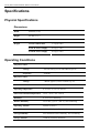
Specifications
Physical Specifications
Dimensions
Width
440 mm (17.4”)
Height
44 mm (1.73”)
Depth
419 mm (16.5”)
Weight
Chassis without PSU
3.7 kg (8.2 lbs)
Each AC Power Supply
0.6 kg (1.3 lbs)
Each DC Power Supply
0.6 kg (1.3 lbs)
Operating Conditions
AC power source
Voltage:
100-120 VAC@ 5A or [email protected]
Frequency:
50/60Hz
DC power source
-48VDC typical (-36V to -60VDC) @ 3A
Voltage:
January 2007
Operating temperature:
0 °C to 45 °C (32 °F to 104 °F)
Short term extended temperature:
-20°C – 60°C (-4°F - 140°F)
Humidity:
0 - 95% non-condensing
Relative Humidity:
5% to 90%, @45 °C (104 °F), non-condensing
Operating Altitude:
6,600 ft (2,012 m)
Storage Temperature:
-25 ºC to 70 ºC (-13 ºF to 158 °F)
Storage Humidity:
95% maximum relative humidity, non-condensing
Storage Altitude:
15,000 ft (4,500 m) maximum
© 2007 Foundry Networks, Inc.
31
Foundry NetIron M2404C/M2404F Metro Access Switches
The equipment is designed for use in indoor
applications only.
Environment:
Management Features
Inband:
Integrated SNMP agent
Java applet , Telnet and SSH
MIBs
Supported:
MIB II, Bridge MIB, Private MIB ,RMON MIB (Groups 1,2,3,9)
Traps/Alarms:
SNMP traps to NMS
Console Port:
For initial configuration via dedicated RJ-45 connector
EIA 232 protocol
VT-100 compatible
Out-of-band
Ethernet Port:
For Software Update via dedicated RJ-45 connector
Software
Download:
Via TFTP
Safety and Electromagnetic Compatibility
Safety
EN/ UL 60950-1, CAN/CSA C22.2 No. 60950-1-03 and IEC 60950:2001
EMC
EN 55022: 1998 + A1:2000 class A, EN 300386 V1.3.1:2001, harmonized under EMC directive
89/336/EEC
EN55024 (CE mark) (Immunity) for Information Technology Equipment
ICES-003 (Canada) (Class A)
AS/NZ 55022 (Australia) (Class A)
VCCI CISPR 22 (Japan) (Class A)
ETSI 300 386 Telecommunication Centers
EN 61000-3-2
EN 61000-3-3
EN 61000-6-1
January 2007
© 2007 Foundry Networks, Inc.
32
Foundry NetIron M2404C/M2404F Metro Access Switches
FCC 47 CFR: 2003 part 15 subpart B, class A
This equipment has been tested and found to comply with the limits for a Class A digital device,
pursuant to Part 15 of the FCC Rules. These limits are designed to provide reasonable protection
against harmful interference when the equipment is operated in a commercial environment. This
equipment generates, uses, and can radiate radio frequency energy and, if not installed and used
in accordance with the instruction manual, may cause harmful interference to radio
communications. Operation of this equipment in a residential area is likely to cause harmful
interference in which case the user will be required to correct the interference at his/her own
expense.
Caution: Changes or modifications made to this device which are not expressly approved by the
party responsible for compliance could void the user’s authority to operate the equipment.
CISPR 22 CLASS A Warning
This is a class A product. In a domestic environment this product may cause radio interference
in which case the user may be required to take adequate measures.
VCCI (Japan) (Class A)
This is a Class A product based on the standard of the Voluntary Control Council for
Interference by Information Technology Equipment (VCCI). If this equipment is used in a
domestic environment, radio disturbance may arise. When such trouble occurs, the user may be
required to take corrective actions.
.
January 2007
© 2007 Foundry Networks, Inc.
33
Foundry NetIron M2404C/M2404F Metro Access Switches
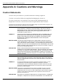
Appendix A: Cautions and Warnings
Caution Statements
A caution calls your attention to a possible hazard that can damage equipment.
"Vorsicht” weist auf die Gefahr einer möglichen Beschädigung des Gerätes in.
Une mise en garde attire votre attention sur un risque possible d'endommagement de
l'équipement. Ci-dessous, vous trouverez les mises en garde utilisées dans ce manuel.
Un mensaje de precaución le advierte sobre un posible peligro que pueda dañar el equipo. Las
siguientes son precauciones utilizadas en este manual.
CAUTION:
Remove the power cord from a power supply before you install it in or remove
it from the device. Otherwise, the power supply or the device could be
damaged as a result. (The device can be running while a power supply is
being installed or removed, but the power supply itself should not be
connected to a power source.)
VORSICHT:
Trennen Sie das Stromkabel vom Netzteil ab, bevor es installiert oder vom
Gerät entfernt wird. Andernfalls kann das Netzteil oder Gerät beschädigt
werden. (Das Gerät kann während der Installation oder Entfernen eines
Netzteils laufen. Allerdings sollte das Netzteil an keine Stromquelle
angeschlossen sein.)
MISE EN GARDE : Afin d'éviter d'endommager le bloc d'alimentation, assurez-vous que le
cordon d'alimentation ne soit pas connecté à une source de courant lorsque
celui-ci est inséré or retiré du châssis. Le commutateur peut fonctionner en
utilisant une source de courant alternative au bloc d'alimentation que l'on veut
insérer ou enlever, mais il est important que celui que l'on insère ou retire ne
soit pas raccordé électriquement.
PRECAUCIÓN
Retire el cable de alimentación de un suministro de energía antes de
instalarlo en él o de retirarlo del dispositivo. De no hacerse así, el suministro
de energía o el dispositivo podrían resultar dañados. (El dispositivo puede
estar funcionando mientras se está instalando o retirando un suministro de
energía, pero el suministro de energía en sí no deberá estar conectado a una
toma de corriente)
CAUTION:
To avoid improper ventilation to the switch’s internal circuitry and units, never
leave an empty slot uncovered. If a removed power supply is not replaced,
insert the supplied blank PSU filler into the slot and fasten it to the panel with
the two screws.
VORSICHT:
Ein leerer Steckplatz darf unter keinen Umständen zugedeckt werden, um eine
mangelnde Be- und Entlüftung der Schaltkreise und Bauteile im Schalter
auszuschließen. Falls ein abentferntes Netzteil nicht wieder ersetzt wird, benutzen
Sie bitte die mitgelieferte Abdeck-Blende und schrauben Sie diese mit den beiden
Schrauben an die Frontplatte
MISE EN GARDE : Pour éviter un dysfonctionnement du circuit de ventilation et ainsi un mauvais
refroidissement des éléments qui composent le dispositif, ne laissez jamais un
emplacement vide non couvert. Si un bloc d’alimentation enlevé n’est pas remplacé,
insérez un cache de bloc d’alimentation dans l’emplacement vide et fixez-le au
panneau avec les deux vis
PRECAUCIÓN:
January 2007
Para evitar una ventilación inadecuada a la circuitería interna y unidades del
interruptor, no deje nunca un slot vacío al descubierto. Si un suministro de
© 2007 Foundry Networks, Inc.
34
Foundry NetIron M2404C/M2404F Metro Access Switches
energía retirado no se reemplaza, inserte el relleno PSU en blanco provisto
en el slot y asegúrelo al panel con los dos tornillos.
CAUTION:
Changes or modifications made to this device that are not expressly
approved by the party responsible for compliance could void the user’s
authority to operate the equipment.
VORSICHT:
Falls dieses Gerät verändert oder modifiziert wird, ohne die ausdrückliche
Genehmigung der für die Einhaltung der Anforderungen verantwortlichen
Partei einzuholen, kann dem Benutzer der weitere Betrieb des Gerätes
untersagt werden.
MISE EN GARDE: Les modifications ou changements apportés à ce dispositif n’ayant pas été
expressément approuvés par la partie responsable d’en évaluer la conformité
peuvent annuler le droit de l’utilisateur à utiliser cet équipement.
PRECAUCIÓN:
Los cambios o modificaciones realizados a este dispositivo que no estén
expresamente aprobados por la parte responsable del cumplimiento de las
normas podrían anular la autoridad del usuario para operar este equipo.
CAUTION:
For a DC system, use a grounding wire of at least 10 American Wire Gauge
(AWG). The 10 AWG wire should be attached to an agency-approved crimp
connector, crimped with the proper tool. The crimp connector should allow for
securement to both ground screws on the enclosure.
VORSICHT:
Für ein Gleichstromsystem ist ein Erdungsdraht (wenigstens 10 AWG)
erforderlich. Der 10 AWG-Draht sollte an einen behördlich genehmigten
Crimpverbinder angebracht werden, der mit einem ordnungsgemäßen
Werkzeug gecrimpt wurde. Der einzelne Crimpverbinder dient der Sicherung
beider Erdungsschrauben am Gehäuse.
MISE EN GARDE: Pour les systèmes C.C., utilisez un fil de mise à la terre de calibre 10 AWG
(American Wire Gauge) minimum. Ce fil doit être relié à un connecteur à
sertir homologué, serti avec l’outil approprié. Le connecteur à sertir unique
devrait permettre le rattachement aux deux vis de borne de terre sur
l’enveloppe.
PRECAUCIÓN:
Para un sistema de corriente continua, utilice cable de conexión a tierra de
calibre 10 AWG (Calibración de cables americana), por lo menos. El cable de
AWG deberá acoplarse a un conector ondulado normalizado, ondulado con
la herramienta apropiada. El conector ondulado simple deberá permitir
fijación a los dos tornillos de conexión a tierra en el armario.
CAUTION
For the DC input circuit to the system, make sure there is a 10 amp circuit on
the input to the terminal block.
VORSICHT:
Für den Eingangs-Gleichstromkreis zum System ist ein 10 ALeistungsschalter am Eingang zur Reihenklemme zu installieren.
MISE EN GARDE: Pour le circuit d’alimentation C.C. du système, assurez-vous de la présence
d’un disjoncteur de 10 ampères sur l’entrée vers le bloc d’alimentation.
PRECAUCIÓN:
January 2007
Para el circuito de entrada de corriente continua al sistema, verifique que
exista un cortacircuitos de 10 amperios en la entrada al bloque terminal.
© 2007 Foundry Networks, Inc.
35
Foundry NetIron M2404C/M2404F Metro Access Switches
Warning Statements
A warning calls your attention to a possible hazard that can cause injury or death. The following
are the warnings used in this manual.
"Achtung" weist auf eine mögliche Gefährdung hin, die zu Verletzungen oder Tod führen
können. Sie finden die folgenden Warnhinweise in diesem Handbuch:
Un avertissement attire votre attention sur un risque possible de blessure ou de décès. Cidessous, vous trouverez les avertissements utilisés dans ce manuel.
Una advertencia le llama la atención sobre cualquier posible peligro que pueda ocasionar daños
personales o la muerte. A continuación se dan las advertencias utilizadas en este manual.
WARNING:
The procedures in this manual are for qualified service personnel.
ACHTUNG:
Die Verfahren in diesem Handbuch sind nur für qualifiziertes
Wartungspersonal gedacht.
AVERTISSEMENT:
Les procédures décrites dans ce manuel doivent être effectuées par le
personnel de service qualifié uniquement.
ADVERTENCIA:
Los procedimientos de este manual se han hecho para personal de
servicio cualificado.
WARNING:
For safety reasons, the ESD wrist strap should contain a series 1 meg
ohm resistor.
ACHTUNG:
Aus Sicherheitsgründen sollte ein EGB-Armband zum Schutz von
elektronischen gefährdeten Bauelementen mit einem 1 MegaohmReihenwiderstand ausgestattet sein.
AVERTISSEMENT:
Pour des raisons de sécurité, la dragonne ESD doit contenir une
résistance de série 1 méga ohm.
ADVERTENCIA:
Por razones de seguridad, la correa de muñeca ESD deberá contener
un resistor en serie de 1 mega ohmio.
WARNING:
The equipment is designed to be used with Class 1 Laser fiber optic
transmitters which may endanger your eyes. Do not look directly into
the fiber optic cables or transmitter.
ACHTUNG:
Die Anlage ist für den Betrieb mit Lichtleitersendern der Klasse 1
ausgelegt, die Ihre Augen gefährden können. Schauen Sie auf keinen
Fall direkt in Lichtleiterkabel oder –sender.
AVERTISSEMENT:
L’équipement est conçu pour être utilisé avec des transmetteurs laser
par fibres optiques de classe 1 qui peuvent endommager vos yeux. Ne
regardez pas directement le transmetteur ou les câbles en fibres
optiques.
ADVERTENCIA:
El equipo está diseñado para utilizarlo con transmisores ópticos de
fibra Láser de Clase 1 que pueden ser perjudiciales para los ojos. No
mire directamente a los cables o al transmisor ópticos de fibra.
WARNING:
HIGH VOLTAGE
Disconnect the product from the power line before removing the cover.
Any adjustment and maintenance of the opened device should be done
only while the device is disconnected from its source of power and
January 2007
© 2007 Foundry Networks, Inc.
36
Foundry NetIron M2404C/M2404F Metro Access Switches
should only be performed by qualified personnel, authorized by
Foundry Networks.
ACHTUNG:
Hochspannung
Trennen Sie das Gerät vom Netz, bevor Sie die Abdeckung abnehmen.
Alle Einstellungs- und Wartungsarbeiten am geöffneten Gerät dürfen
nur von Fachleuten durchgeführt werden, die eine Foundry Networks
Zertifizierung nachweisen können. Diese Arbeiten dürfen nur an einem
von seiner Stromquelle abgetrennten Gerät erfolgen.
AVERTISSEMENT :
Haute tension
Débranchez le produit de sa source d’alimentation avant de retirer le
couvercle. Tout ajustement ou toute maintenance d’un dispositif ouvert
doit être effectué uniquement lorsque le dispositif est hors tension et
doit être effectué uniquement par du personnel qualifié, agréé par
Foundry Networks.
ADVERTENCIA:
Alto voltaje
Desconecte el producto de la alimentación de corriente antes de retirar
la cubierta. Cualquier ajuste o mantenimiento realizado al dispositivo
abierto deberá hacerse únicamente cuando el dispositivo esté
desconectado de su toma de corriente, y solo deberá ser realizada por
personal calificado y autorizado por Foundry Networks.
WARNING:
GROUNDING
Before connecting the product to the power line, make sure that the
protective ground terminal of the device is connected to the safety
ground conductor of the mains power cord.
The main power supply plug should only be inserted in a socket outlet
provided with a connected safety ground. The protective action must
not be negated by use of an extension cord (power cable) without a
protective conductor (grounding). Any interruption of the protective
(grounding) conductor or disconnection of the protective ground
terminal can make the device unsafe to use. Intentional interruption is
prohibited.
This equipment has a connection between the earthed conductor of the
DC supply circuit and the grounding conductor.
ACHTUNG:
ERDUNG
Stellen Sie sicher, dass der Schutzerdanschluss des Geräts an den
Sicherheitserdleiter des Hauptnetzkabels angeschlossen ist, bevor das
Gerät an das Netz angeschlossen wird.
Der Hauptnetzstecker darf nur in eine Steckdose mit angeschlossener
Sicherheitserde gesteckt werden. Diese Schutzfunktion darf nicht durch
den Gebrauch eines Verlängerungsstromkabels ohne Schutzleiter
(Erde) außer Kraft gesetzt werden. Alle Unterbrechungen des
Schutzerdleiters oder Abtrennen vom Schutzerdanschluss machen die
Benutzung des Gerätes gefährlich. Eine absichtliche Unterbrechung ist
verboten.
Diese Anlage weist einen Anschluss zwischen dem Erdleiter des
Gleichstromkreises und dem Schutzleiter auf.
Avertissement :
Mise à la terre.
Avant de brancher l’unité à une source de courant, vérifiez que la prise
de terre est branchée à la mise à la terre du câble d’alimentation
secteur.
January 2007
© 2007 Foundry Networks, Inc.
37
Foundry NetIron M2404C/M2404F Metro Access Switches
La prise d’alimentation principale doit être insérée uniquement dans
une prise ayant un raccordement à la terre. Cette protection ne doit pas
être remise en cause par l’utilisation d’une rallonge (câble
d’alimentation) ne possédant pas de mise à la terre. Toute discontinuité
du circuit de mise à la terre ou déconnexion de la prise de terre risque
de rendre l’utilisation du dispositif dangereuse. Toute interruption
intentionnelle est interdite.
Cet équipement possède un raccordement entre la mise à la terre du
circuit d’alimentation continue (DC) et le câble de la mise à la terre.
ADVERTENCIA:
CONEXIÓN A TIERRA
Antes de conectar el producto a la corriente, verifique que el terminal
protector de conexión a tierra del dispositivo esté conectado al
conductor de seguridad de conexión a tierra del cable de alimentación
principal.
El enchufe del suministro de energía principal solo deberá insertarse
en una toma de zócalo provista con una toma de tierra de seguridad
conectada. No deberá denegarse la acción protectora por el uso de
cable de extensión (cable de alimentación) sin un conductor protector
(conexión a tierra). Cualquier interrupción del conductor protector
(conexión a tierra) o la desconexión del terminal protector de conexión
a tierra pueden hacer que el uso del dispositivo resulte peligroso. Esta
prohibida la interrupción intencional.
Este equipo cuenta con una conexión entre el conductor conectado a
tierra del circuito de suministro de CC y el conductor de conexión a
tierra.
WARNING:
WIRING FOR NATIONAL POWER PLUG
A mains power cable according to National Electrical Code (NEC) with
molded IEC socket is supplied with each unit. The specific national
mains power plug should be wired as follows:
ACHTUNG:
Brown lead
Live (phase)
Blue lead
Neutral
Green/Yellow lead
Safety ground
VERDRAHTUNG DES NATIONAL-STECKERS
Ein Hauptnetzstromkabel gemäß NEC (National Electric Code der
USA) mit in Kunststoff gegossener IEC-Buchse wird mit jeder Einheit
geliefert. Der National-Hauptnetzstecker ist wie folgt zu verdrahten:
AVERTISSEMENT :
Braune Leitung
Stromführend (Phase)
Blaue Leitung
Neutral
Grüngelbe Leitung
Sicherheitserde.
CÂBLAGE POUR PRISE D’ALIMENTATION NATIONALE
Un câble d’alimentation secteur selon le code national de l’électricité
(National Electric Code ou NEC) avec une prise IEC moulée est fourni
avec chaque unité. La prise d’alimentation secteur nationale spécifique
doit être câblée comme suit:
January 2007
Fil marron
Phase
Fil bleu
Neutre
Fil vert/jaune
Terre
© 2007 Foundry Networks, Inc.
38
Foundry NetIron M2404C/M2404F Metro Access Switches
ADVERTENCIA:
CABLEADO PARA ENCHUFE DE CORRIENTE NACIONAL
Con cada unidad se suministra un cable de alimentación principal
según el Código eléctrico nacional (National Electrical Code o NEC)
con zócalo IEC moldeado. El enchufe de alimentación principal
específico deberá estar cableado de la manera siguiente:
WARNING:
Conductor marrón
Activo (fase)
Conductor azul
Neutro
Conductor verde/amarillo
Conexión a tierra de seguridad
LINE VOLTAGE
Before connecting the product to the power line, make sure the voltage
of the power source matches the requirements of the product, as
marked on the label located near the power connectors
ACHTUNG:
NETZSPANNUNG
Stellen Sie sicher, dass die Spannung der Stromquelle den
Geräteanforderungen entspricht (siehe Etikett neben den
Netzanschlüssen), bevor Sie das Gerät an das Netz anschließen.
AVERTISSEMENT :
TENSION DU RÉSEAU
Avant de brancher le produit à l’alimentation électrique, vérifiez que le
voltage de la source d’alimentation correspond aux spécifications du
produit, telles qu’elles sont portées sur l’étiquette en regard des
connecteurs d’alimentation.
ADVERTENCIA:
VOLTAJE DE LÍNEA
Antes de conectar el producto a la línea de alimentación, verifique que
el voltaje de la fuente de alimentación se ajusta a los requisitos del
producto, según lo indicado en la etiqueta situada junto a los
conectores de alimentación.
WARNING:
DC POWER SOURCE
The DC power source should be protected with a branch circuit overcurrent protection rated at 10Amp, located in the building installation.
ACHTUNG:
GLEICHSTROMQUELLE
Die Gleichstromquelle ist mit einem Zweigstromkreis mit
Überstromschutz (10 A) in der Gebäudeinstallation zu schützen
AVERTISSEMENT :
SOURCE D’ALIMENTATION C.C.
La source d’alimentation continue (DC) doit être protégée par
disjoncteur de 10A, situé dans l’installation du bâtiment.
ADVERTENCIA:
FUENTE DE ALIMENTACIÓN DE CC
La fuente de alimentación de CC deberá protegerse con un circuito en
bifurcación contra sobretensión con capacidad nominal de 10 Amp,
situado en la instalación del edificio
January 2007
WARNING:
Make sure the rack or cabinet housing the device is adequately
secured to prevent it from becoming unstable or falling over.
ACHTUNG:
Das Gestell oder der Schrank muss standfest und stabil aufgestellt
werden.
© 2007 Foundry Networks, Inc.
39
Foundry NetIron M2404C/M2404F Metro Access Switches
AVERTISSEMENT:
Vérifiez que le chassis ou l’armoire incluant l’unité est bien fixé afin qu’il
ne devienne pas instable ou qu’il ne risque pas de tomber.
ADVERTENCIA:
Verifique que el montante o el gabinete que alberga el dispositivo está
asegurado adecuadamente para evitar que se haga inestable o que se
caiga.
WARNING:
Before connecting power to the switch, make sure that both grounding
posts in the rear panel are firmly connected to a reliable ground through
a #10 AWG grounding wire terminated by a UL-listed two-hole longbarrel 5/8 10 AWG compression lug with hole size and spacing as
shown in Figure 15.
The Burndy YAZV10-2TC14 or an equivalent UL-listed two-hole
compression lug is recommended.
ACHTUNG:
Stellen Sie sicher, dass die beiden Erdungsstäbe in der Rückwand fest
mit einem 2,59 mm dicken Draht (AWG 10) an eine zuverlässige Erde
angeschlossen sind. Der Draht muss mit einem UL-zugelassenen
langen Kabelschuh (5/8 AWG 10) mit zwei Löchern abgeschlossen
werden. Für Lochdurchmesser und Abstand siehe die folgende
Abbildung Figure 15.
Als Kabelschuh wird das Modell Burndy YAZV10-2TC14 oder ein
gleichwertiger UL-zugelassener langer Kabelschuh mit zwei Löchern
empfohlen
AVERTISSEMENT:
Avant de brancher le commutateur à une source de courant, vérifiez
que les fiches de mise à la terre du panneau arrière sont fermement
connectées à une prise de terre fiable. Pour cela, utilisez un fil de mise
à la terre de calibre 10 AWG se terminant par une cosse à
compression 5/8 10 AWG cylindrique longue à deux trous, homologuée
UL. Espacement et taille de trou sont indiqués dans Figure 15 cidessous.
La cosse à compression deux trous homologuée UL Burndy YAZV102TC14 ou équivalente est recommandée.
ADVERTENCIA:
Antes de conectar la alimentación al interruptor, verifique que ambos
postes de conexión a tierra del panel posterior estén bien conectados a
una tierra de confianza por medio de un cable de conexión a tierra de
calibre #10 AWG de 5/8 terminado en una garra de compresión de
calibre10 AWG de 5/8 de rodillo largo con dos agujeros listada por UL
con tamaño de agujero, según se muestra en Figure 15 más abajo.
Se recomienda Burndy YAZV10-2TC14 o una garra de compresión con
dos agujeros equivalente listada por UL.
January 2007
© 2007 Foundry Networks, Inc.
40