1
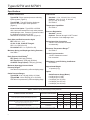
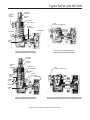
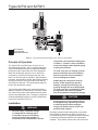
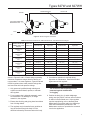
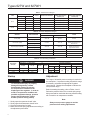
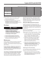
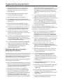
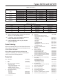
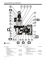
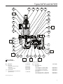
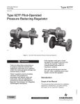
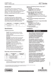
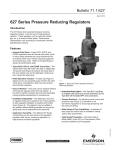
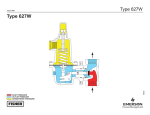
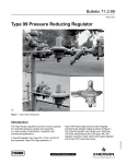
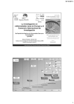
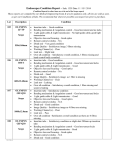
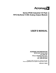
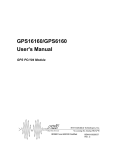
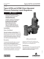
Types 627W and 627WH
Instruction Manual
Form 5447
March 2009
Types 627W and 627WH Direct-Operated
Pressure Reducing Liquid Regulators
!
Warning
Fisher® regulators must be installed,
operated, and maintained in accordance
with federal, state, and local codes,
rules and regulations, and
manufacturer’s instructions.
Installation, operation, and maintenance
procedures performed by unqualified
personnel may result in improper
adjustment and unsafe operation.
Either condition may result in
equipment damage or personal
injury. Use qualified personnel when
installing, operating, and maintaining
the Types 627W and 627WH regulators.
Introduction
Scope of the Manual
This Instruction Manual provides installation, startup,
adjustment, maintenance, and parts ordering
information for the Types 627W and 627WH pressure
reducing regulators for liquid service. Only personnel
qualified through training or experience should install,
operate, and maintain these regulators. If there are
any questions concerning these instructions, contact
your local Sales Office before proceeding.
Description
W4793
Figure 1. Types 627W and 627WH
Pressure Reducing Liquid Regulator
The Types 627W and 627WH (Figure 1) are directoperated pressure reducing regulators for liquid
service. On the internal registration version,
downstream pressure is registered internally through
the body to the underside of the diaphragm.
seal and a 1/4 NPT control line connection in the
diaphragm case. The stem seal separates the body
outlet pressure from the diaphragm case.
Types 627W and 627WH direct-operated regulators
are also available in a downstream control line version
for external pressure registration. The control line
version has a blocked throat with an O-ring stem
Refer to Specifications lists for Types 627W and 627WH
constructions on page 2. Specifications for a given
regulator as it originally comes from the factory are
stamped on the spring case nameplate.
D102504X012
Specifications
www.emersonprocess.com/regulators
Types 627W and 627WH
Specifications
Available Construction
Orifice Sizes
Type 627W: Direct-operated pressure reducing
liquid regulator (Figure 2)
Type 627WH: Type 627W with a diaphragm
limiter to deliver a higher outlet pressure
(Figure 2)
Control Line Option: Type 627W or 627WH
with a stem seal between the body outlet pressure
and diaphragm case. Pressure is measured under
the diaphragm through the 1/4 NPT downstream control line connection (Figure 2)
Body Sizes and End Connection Styles
Temperature Capabilities
See Table 4
Pressure Registration
Standard: Internal
Optional: External through 1/4 NPT control
line connection in the diaphragm case
Spring Case Vent Connection
3/4 NPT with removable screened vent assembly
NPT: NPS 3/4, 1, or 2
CL150, CL300, CL600 RF Flanged:
NPS 1 or 2 (DN 25 or 50)
PN 16/25/40: NPS 1 or 2 (DN 25 or 50)
Maximum Spring and Diaphragm Casing Pressure(1)
See Table 1
Body Pressure Shell Rating
(1)
NPT (Steel): 2000 psig (138 bar)
NPT (Ductile Iron): 1000 psig (68,9 bar)
CL600 RF Flanged (Steel): 1500 psig (103 bar)
Elastomer Temperature Ranges(1)
See Table 4
Control Line Connection
1/4 NPT downstream control
line connection
Wide-Open Cv and IEC Sizing Coefficients
See Table 5
Maximum Operating Inlet and Outlet
Pressure Ranges(1)
See Table 2 for pressures by orifice and spring range
Approximate Weight
10 pounds (5 kg)
Option
Outlet Pressure Ranges
Standard: 1/4 or 1/2-inch (6,4 or 13 mm)
Optional: 3/32,1/8, 3/16, or 3/8-inch (2,4; 3,2; 4,8; or 9,5 mm)
See Table 8
Type 627W: 10 to 150 psig (0,69 to 10,3 bar)
Type 627WH: 140 to 500 psig (9,7 to 34,5 bar)
See Table 2 for pressures by orifice and spring range
Outlet Pressure Gauge (Brass):
0 to 30 psi (0 to 2,1 bar)
0 to 60 psi (0 to 4,1 bar)
0 to 160 psi (0 to 11,0 bar)
0 to 300 psi (0 to 20,7 bar)
0 to 600 psi (0 to 41,4 bar)
1. The pressure/temperature limits in this Instruction Manual or any applicable standard limitation should not be exceeded.
Table 1. Maximum Spring and Diaphragm Casing Pressure(1)
TYPE 627WH
DIAPHRAGM CASING material
Psig
bar
Psig
bar
Maximum pressure to spring and diaphragm casings to prevent
leak to atmosphere (internal parts damage may occur)
Ductile iron
250
17,2
----
----
Steel or Stainless steel
250
17,2
800
55,2
Ductile iron
465
32,1
----
----
Steel or Stainless steel
1500
103
1500
103
All materials
60
4,1
120
8,3
Maximum pressure to spring and diaphragm casings to prevent
burst of casings during abnormal operation (leak to atmosphere
and internal parts damage may occur)
Maximum diaphragm casing overpressure (above setpoint) to
prevent damage to internal parts
1. If the spring case is pressurized, a metal adjusting screw cap is required. Contact your local Sales Office for details.
2
TYPE 627W
MAXIMUM PRESSURE DESCRIPTION
Types 627W and 627WH
SCREENED
VENT
ASSEMBLY
ADJUSTING
SCREW CAP
ADJUSTING
SCREW
SPRING CASE
CONTROL SPRING
1/4 NPT
CONTROL LINE CONNECTION
INTERNAL
REGISTRATION
DISK ASSEMBLY
DIAPHRAGM
PUSHER
POST
W6483-2
W6306-1
DETAIL OF TYPE 627W WITH EXTERNAL
DOWNSTREAM PRESSURE REGISTRATION
DETAIL OF TYPE 627W WITH INTERNAL
DOWNSTREAM PRESSURE REGISTRATION
ADJUSTING
SCREW CAP
ADJUSTING
SCREW
SCREENED
VENT
ASSEMBLY
SPRING CASE
1/4 NPT
CONTROL LINE CONNECTION
CONTROL SPRING
DIAPHRAGM
LIMITER
O-RING
DIAPHRAGM
head
INTERNAL
REGISTRATION
DISK ASSEMBLY
DIAPHRAGM
LIMITER
DIAPHRAGM
PUSHER
POST
W5482-1
W6305-1
DETAIL OF TYPE 627WH WITH INTERNAL
DOWNSTREAM PRESSURE REGISTRATION
DETAIL OF TYPE 627WH WITH EXTERNAL DOWNSTREAM PRESSURE
REGISTRATION AND CONNECTION FOR OUTLET PRESSURE GAUGE
Figure 2. Types 627W and 627WH Construction Details
3
Types 627W and 627WH
Type 627W
July 2008
Type 627W
M1037
M1037
inlet
INLETpressure
PRESSURE
OUTlet
pressure
OUTLET
PRESSURE
ATMOSPHERIC
pressure
ATMOSPHERIC
INLET PRESSURE PRESSURE
OUTLET PRESSURE
ATMOSPHERIC PRESSURE
Figure 3. Type 627W Operational Schematic (Also Typical of Type 627WH)
Principle of Operation
The Type 627W or 627WH (refer to Figure 2) is a
direct-operated regulator. On the internal registration
version, downstream pressure is registered internally
through the body to the under side of the diaphragm.
When the downstream pressure is at or above the
set pressure, the disk is held against the seat, and
there is no flow through the regulator. When demand
increases, downstream pressure drops slightly allowing
the spring to extend, moving the stem down and the
disk away from the seat. This allows flow through the
body to the downstream system.
Types 627W and 627WH direct-operated regulators
are also available in a downstream control line version.
This version has a stem seal between the body outlet
pressure and diaphragm case. Pressure is registered
under the diaphragm through the 1/4 NPT downstream
control line connection (Figure 2).
Installation
!
Warning
Personal injury, equipment damage,
or leakage due to escaping liquid
or bursting of pressure-containing
parts may result if this regulator is
overpressured or installed where service
4
connection could exceed the limits given
in Tables 1, 2, and 4 or where conditions
exceed any ratings of the adjacent piping
or piping connections.
To avoid such injury or damage, provide
pressure-relieving or pressure-limiting
devices to prevent service conditions
from exceeding those limits.
Additionally, the control line could be
broken off the regulator by physical
damage, causing personal injury and
property damage due to escaping liquid.
To avoid such injury and damage, install
the regulators and control line where
they are protected from physical damage.
caution
Liquid pressure control systems should
be designed using engineering practices
to eliminate quick control starting or
stopping of the flow stream, which can
produce water hammer.
Regulator operation within ratings does not preclude
the possibility of damage from debris in the lines or
from external sources. A regulator should be inspected
for damage periodically and after any overpressure
condition. Key numbers referenced in this section are
Types 627W and 627WH
working regulator
control line
monitor
Type 627W set higher than
working regulator
INLET
TYPE 627W
A6623
TYPE 627W
Figure 4. Monitor Regulator Schematic
Table 2. Maximum Inlet Pressure, Differential Pressure, and Outlet Pressure Ranges
Type
627W
627WH
OUTLET PRESSURE
RANGE, SPRING PART Orifice Size,
NUMBER, AND COLOR, Inches (mm)
PSIG (bar)
Maximum Inlet Pressure, Psig (bar)
Maximum Differential Pressure, Psid (bar d)
Elastomer Disk
Nylon Disk
Elastomer Disk
Nylon Disk
10 to 20 (0,69 to 1,4)
10B3076X012
Yellow
1/4 (6,4)
220 (15,2)
420 (29,0)
200 (13,8)
400 (27,6)
1/2 (13)
220 (15,2)
250 (17,2)
200 (13,8)
250 (17,2)
15 to 40 (1,0 to 2,8)
10B3077X012
Green
1/4 (6,4)
240 (16,5)
440 (30,3)
200 (13,8)
400 (27,6)
1/2 (13)
240 (16,5)
300 (20,7)
200 (13,8)
300 (20,7)
35 to 80 (2,4 to 5,5)
10B3078X012
Blue
1/4 (6,4)
280 (19,3)
480 (33,1)
200 (13,8)
400 (27,6)
1/2 (13)
280 (19,3)
480 (33,1)
200 (13,8)
400 (27,6)
70 to 150 (4,8 to 10,3)
10B3079X012
Red
1/4 (6,4)
350 (24,1)
550 (37,9)
200 (13,8)
400 (27,6)
1/2 (13)
350 (24,1)
550 (37,9)
200 (13,8)
400 (27,6)
140 to 250 (9,7 to 17,2)
10B3078X012
Blue
1/4 (6,4)
450 (31,0)
650 (44,8)
200 (13,8)
400 (27,6)
1/2 (13)
450 (31,0)
500 (34,5)
200 (13,8)
250 (17,2)
240 to 500 (16,5 to 34,5)
10B3079X012
Red
1/4 (6,4)
700 (48,3)
900 (62,1)
200 (13,8)
400 (27,6)
1/2 (13)
700 (48,3)
750 (51,7)
200 (13,8)
250 (17,2)
shown in Figures 5 and 6. Ensure that the operating
elastomer temperature ranges listed in Table 4 are
not exceeded. Like most regulators, Types 627W and
627WH regulators have outlet pressure ratings that
are lower than their inlet pressure ratings.
1. Only personnel qualified through training and
experience should install, operate, or maintain
this regulator.
2. For a regulator that is shipped separately, make
sure that there is no damage to, or foreign
material in, the regulator.
3. Ensure that all tubing and piping have been blown
free of foreign debris.
4. The regulator may be installed in any position as
long as the flow through the body is in the
direction indicated by the arrow cast on the body.
5. If continuous operation is required during
inspection or maintenance, install a three-valve
bypass around the regulator.
!
Warning
The vent line or stack opening must be
protected against condensation
or clogging.
6. Position the body (key 1) and/or diaphragm
spring case (key 29) so it will not collect moisture
or debris in the screened vent. If the regulator
requires repositioning, refer to the Body Area
Maintenance Procedures and/or the diaphragm
case area maintenance procedures in the
Maintenance section to reposition the screened
vent for the application.
5
Types 627W and 627WH
Table 3. Outlet Pressure Ranges
SPRING RANGE
COLOR
SPRING PART NUMBER
SPRING FREE LENGTH,
INCHES (mm)
SPRING WIRE DIAMETER,
INCHES (mm)
0,69 to 1,4
Yellow
10B3076X012
3.19 (81,0)
0.170 (4,32)
15 to 40
1,0 to 2,8
Green
10B3077X012
3.19 (81,0)
0.207 (5,26)
35 to 80
2,4 to 5,5
Blue
10B3078X012
3.20 (81,3)
0.262 (6,66)
70 to 150
4,8 to 10,3
Red
10B3079X012
3.07 (78,0)
0.313 (7,95)
140 to 250
9,7 to 17,2
Blue
10B3078X012
3.20 (81,3)
0.262 (6,66)
240 to 500
16,5 to 34,5
Red
10B3079X012
3.07 (78,0)
0.313 (7,95)
TYPE
627W
627WH
Psig
bar
10 to 20
Table 4. Elastomer Temperature Ranges
MATERIAL
TEMPERATURE RANGE
DISK/DIAPHRAGM
Disk
Nitrile (NBR)
Diaphragm
Disk
Fluorocarbon (FKM)
Diaphragm
Disk
Ethylenepropylene (EPDM)
Diaphragm
USAGE
°F(1)
°C(1)
-40 to 180
-40 to 82
General
0 to 300
-18 to 149
Not Recommended for Hot
Water Service
-40 to 275
-40 to 135
Not Recommended for
Hydrocarbon Service
Perfluoroelastomer (FFKM)
Disk
0 to 400
-18 to 204
Corrosive
Nylon (PA)
Disk
-40 to 200
-40 to 93
General
Polytetrafluoroethylene (PTFE)
Diaphragm Protector
-40 to 400
-40 to 204
Corrosive
1. Stainless steel body is rated to -40°F (-40°C). Steel and ductile iron bodies are rated to -20°F (-29°C).
Table 5. Flow and Sizing Coefficients
ORIFICE SIZE, INCHES (mm)
BODY SIZES,
NPS (DN)
Wide-Open CV for Relief Sizing
1/4 (6,4)
1/2 (13)
3/4
1.63
4.87
1 (25)
1.70
5.29
2 (50)
1.66
5.01
Km
1/4 (6,4)
IEC Sizing Coefficients
1/2 (13)
0.76
Startup
FD
1/4 (6,4)
1/2 (13)
0.592
0.962
0.543
0.815
0.620
1.01
FL
1/4 (6,4)
1/2 (13)
1/4 (6,4)
1/2 (13)
0.50
0.50
0.87
0.86
Adjustment
!
Warning
To avoid personal injury or property
damage during startup, release
downstream pressure to prevent
an overpressure condition on the
diaphragm of the regulator. In order to
avoid an overpressure condition and
possible equipment damage, pressure
gauges should always be used to
monitor pressure during startup.
1. Slowly open the upstream shutoff valve.
2. Slowly open the downstream shutoff valve.
3. Check all connections for leaks.
4. Make final control spring adjustments according to the adjustment procedures.
6
0.74
XT
The range of allowable pressure settings is marked on
the nameplate. If a pressure setting beyond this range
is necessary, substitute the appropriate regulator
control spring. Change the nameplate to indicate the
new pressure range.
Before increasing the setting, refer to Tables 1 and 2.
Review the pressure limits for the control spring range
being used and be certain that the new pressure setting
will not result in an overpressure condition.
Note
Always use a pressure gauge to monitor
pressure when making adjustments.
Types 627W and 627WH
Table 6. Maximum Torque Values
Key Number
Description
Foot Pounds
Newton Meters
2
Orifice
25
34
3
Cap Screw (with ductile iron or steel diaphragm casing)
25
34
9
(1)
18
37
Lever, Cap Screw
7
Spring Case Cap Screw (with ductile iron diaphragm casing)
7
9
Spring Case Cap Screw (with steel diaphragm casing)
35
47
Diaphragm Cap Screw (Type 627W)
7
9
Diaphragm Cap Screw (Type 627WH)
14
19
46
1. Refer to Figures 5 and 6 for key numbers.
Refer to Figures 5 and 6 for key number location.
1. Remove the adjusting screw cap (key 36).
2. Loosen the locknut (key 34).
3. Increase the outlet pressure setting by turning
the adjusting screw (key 35) clockwise.
Decrease the outlet pressure settings by turning
the adjusting screw counterclockwise.
Shutdown
!
Warning
To avoid personal injury or property
damage or damage to regulator or
downstream components during
shutdown, release downstream pressure
to prevent an overpressure condition on
the diaphragm of the regulator.
1. Close the nearest upstream shutoff valve.
2. Close the nearest downstream shutoff valve.
3. Open the vent between the regulator and the downstream shutoff valve nearest to it.
Maintenance
Unless otherwise specified the following maintenance
procedures apply to all Types 627W and 627WH
regulators. For a summary of maximum torque values,
refer to Table 6.
Due to normal wear, damage from external sources,
or debris in the line, regulator parts such as the
valve plug assembly, orifice, and diaphragm must be
inspected periodically and replaced as necessary to
ensure correct performance.
The frequency of inspection and replacement depends
upon the severity of conditions and the requirements
of state and federal laws and regulations. Normal
wear of the orifice and disk assembly is accelerated
with high pressure drops and with large amounts of
impurities in the flow stream. Instructions are given
below for replacing the valve plug assembly, orifice,
diaphragm, and O-rings. These procedures may also
be used for disassembly required for inspection and
replacement of other parts.
Body Area Maintenance Procedures
These procedures are for gaining access to the
valve plug assembly, orifice, lower casing O-ring and
stem assembly. All pressure must be released from
the diaphragm casing before the following steps can
be performed.
While using the following procedures, refer to Figures 5
and 6 for key number location.
Replacing the Valve Plug Assembly or Orifice
1. To inspect and replace the valve plug assembly
(key 9) or orifice (key 2), remove the cap screws
(key 3, not shown), and separate the lower
diaphragm casing (key 5) from the body (key 1).
2. Inspect and, if necessary, remove the orifice
(key 2). If removed, coat the threads of the
replacement orifice with lubricant (key 38) and
tighten to 25 foot-pounds (34 N•m).
3. Inspect the valve plug assembly (key 9) and, if
necessary, remove the hair pin clip (key 13) that
holds the valve plug assembly in place. If
replacing the valve plug assembly is the only
maintenance required, skip to step 10.
Replacing the Stem Assembly
If it is necessary to perform maintenance on the stem
assembly, continue with steps 4 through 13.
4. Remove the stem guide (key 8) from the lower
diaphragm casing (key 5). Unhook from the lever
(key 15) and remove the stem (key 10) from the
lower diaphragm casing (key 5).
7
Types 627W and 627WH
5.
Remove and inspect the stem O-ring (key 11)
and replace if necessary. Also inspect and if
necessary replace the O-ring (key 44) and
backup springs.
6. Remove and inspect the stem backup rings
(key 12) and replace if necessary.
7. Apply lubricant to the stem O-ring (key 11).
3. Remove the diaphragm limiter (key 50) and
O-ring (key 51) on the Type 627WH only. Remove
the diaphragm assembly by tilting it so that the
pusher post assembly (key 19) slips off the lever
(key 15).
4. If it is necessary to replace the lever assembly
(key 15), remove the lever cap screws (key 18).
9. Insert parts into the lower diaphragm casing
(key 5) that were removed in steps 4 through 6.
5. Install the replacement lever (key 15) into the lever
retainer (key 16) by inserting the lever pin
(key 17). Secure the lever assembly (key 15)
into the lower diaphragm casing (key 5) with the
cap screws (key 18) and tighten the cap screw to
7 foot-pounds (9 N•m).
10. Install the valve plug assembly (key 9), line up
the hole in the valve plug assembly and stem
(key 10) and insert the hair pin clip (key 13).
If it is necessary to perform maintenance on the
diaphragm assembly continue with steps 6 through 10
and step 17, otherwise skip to step 11.
11. Position the diaphragm casing plus attached
parts in relation to the body (key 1) so that they
are correct for the application.
6.
8. For assembly, insert the stem (key 10) into the
lower diaphragm casing (key 5) and hook it on the
lever (key 15).
12. Secure the lower diaphragm casing to the body
with the cap screw (key 3). For ductile iron or
steel diaphragm casings, tighten the cap screws
(key 3) to 25 foot-pounds (34 N•m).
13. It may be necessary to reposition the diaphragm
spring case to prevent rain, ice, and foreign
debris from entering the spring case. Refer to
the Diaphragm and Spring Case Area
Maintenance Procedures.
Remove cap screw (key 46), lower spring seat
(key 31 for Type 627W only, Figure 5) and
diaphragm head (key 24). On the Type 627WH
remove O-ring (key 52, Figure 6). Separate the
diaphragm (key 23) from the pusher post (key 19).
7. Install the diaphragm (key 23), in reverse order of
step 6. On the pusher post (key 19), insert and
finger tighten the cap screw (key 46).
8. Hook the pusher post (key 19) on the lever
(key 15), then turn the diaphragm (key 23) to
match the holes in the diaphragm with the holes in
the lower diaphragm casing (key 5).
Diaphragm and Spring Case Area
Maintenance Procedures
9. Unhook the pusher post (key 19) from the lever
(key 15) and tighten the cap screw (key 46) to
7 foot-pounds (9 N•m).
These procedures are for gaining access to the control
spring, diaphragm assembly, and lever assembly. All
spring pressure must be released from the diaphragm
casing before these steps can be performed.
10. Hook the pusher post (key 19) on the lever
(key 15) and check the hole alignment. If
necessary, loosen the cap screw (key 46) and
reposition the diaphragm (key 23) on the pusher
post (key 19). Tighten the cap screw to 7 footpounds (9 N•m).
While using the following procedures, refer to Figures 5
and 6 for key number locations.
1. Remove the adjusting screw cap (key 36), loosen
the lock nut (key 34), and turn the adjusting screw
(key 35) counterclockwise until all compression is
removed from the control spring (key 32).
2. Remove the cap screws (key 37), and lift off
the spring case (key 29). If changing the spring
(key 32) or repositioning the spring case is the
only maintenance required, install the replacement
spring (key 32) or rotate the spring case so it
is correct for the application. Skip to step 13. For
diaphragm area maintenance, continue with step 3.
8
11. Insert the diaphragm assembly into the lower
diaphragm casing (key 5).
12. Install the spring (key 32) and upper spring seat
(key 33), and apply lubricant to the upper
spring seat.
13. Install the spring case (key 29) so that the vent
(key 30) is in the correct position for the
application. Insert the cap screws (key 37) and
finger tighten.
14. Screw in the adjustment screw (key 35) to put
slack into the diaphragm (key 23).
Types 627W and 627WH
Table 7. Body (Key 1)
END CONNECTION STYLE
NPT
Cl150 RF
CL300 RF
CL600 RF
PN 16/25/40
BODY MATERIAL
Ductile Iron (Type 627W only)
WCC Steel
CF8M Stainless Steel
WCC Steel
CF8M Stainless Steel
WCC Steel
CF8M Stainless Steel
WCC Steel
CF8M Stainless Steel
WCC Steel
CF8M Stainless Steel
NPS 3/4
30B3046X012
30B3050X012
30B3050X062
-------------------------
NPS 1 (DN 25)
30B3048X012
30B3051X012
30B3051X092
43B8656X022
43B8656X052
41B8978X012
41B8978X072
40B6754X012
40B6754X102
44B0386X012
44B0386X032
NPS 2 (DN 50)
30B3096X012
30B7452X012
30B7452X052
44B0666X012
44B0666X022
41B8080X012
41B8080X072
40B6756X012
40B6756X062
44B3342X012
44B3342X032
Table 8. Orifice (Key 2)
ORIfiCE DIAMETER
Inches
3/32
1/8
3/16
1/4
3/8
1/2
PART NUMBER
mm
2,4
3,2
4,8
6,4
9,5
13
303 Stainless Steel
0R044135032
1A936735032
00991235032
0B042035032
0B042235032
1A928835032
15. Using a crisscross pattern, tighten the cap screw
(key 37) to 7 foot-pounds (9 N•m).
16. If necessary, refer to the installation and/or the
startup and adjustment procedures.
17. Install the adjusting screw cap (key 36) after
regulator adjustment.
Parts Ordering
When corresponding with your local Sales Office about
this equipment, always reference the information found
on the regulator nameplate.
When ordering replacement parts, reference the
complete 11-character part number of each needed
part as found in the following parts list.
Parts List
Key Description
Part Number
1
Body (See Table 7)
2*
Orifice (See Table 8)
3
Cap Screw (2 required, Not shown)
Ductile iron or steel
spring case and diaphragm casing
(plated steel cap screw)
Stainless steel spring case and
diaphragm casing (SST cap screw)
5
Lower Diaphragm Casing
Type 627W
Ductile iron
WCC Steel
CF8M Stainless steel
1A560724052
1A5607X0052
30B3053X012
30B3104X012
30B3104X082
316 Stainless Steel
0R0441X0012
1A9367X0022
009912X0012
0B0420X0012
0B0422X0012
1A9288X0012
Key Description
5
Lower Diaphragm Casing (continued)
Type 627W with control line or 1/4 NPT Tap
Ductile iron
WCC Steel
CF8M Stainless steel
Type 627WH
WCC Steel
CF8M Stainless steel
Type 627WH with control line or 1/4 NPT Tap
WCC Steel
CF8M Stainless steel
Part Number
39A5987X012
30B8734X012
30B8734X032
30B3104X012
30B3104X082
30B8734X012
30B8734X032
8
Stem Guide, 316 Stainless steel
Standard
With control line
14B7259X012
10B3085X012
9* Valve Plug Assembly
Stainless steel/Nitrile (NBR)
Stainless steel/Nylon (PA)
Stainless steel/Fluorocarbon (FKM)
Stainless steel/Ethylenepropylene (EPDM)
Stainless steel/Perfluoroelastomer (FFKM) 1C4248X0202
1C4248X0062
1C4248X0052
1C4248X0302
1C4248X0392
10
10B3059X012
Stem, 416 Stainless steel
11* Stem O-Ring (material same as diaphragm)
Nitrile (NBR)
Fluorocarbon (FKM)
Ethylenepropylene (EPDM)
Perfluoroelastomer (FFKM)
(with Diaphragm Protector)
1D687506992
1N430406382
1D6875X0032
1D6875X0082
12* Stem Backup Ring,
Polytetrafluoroethylene (PTFE) (2 required)
1K786806992
13
Hair Pin Clip, Stainless steel
10B3058X012
14
Drive Pin, Stainless steel
1H3671X0012
15
Lever, 304 Stainless steel
20B3063X022
16
Lever Retainer, Stainless steel
34B6659X012
17
Lever Pin, Stainless steel
10B3083X022
18
Cap Screw, 18-8 Stainless steel (2 required)
1B2905X0012
19
Pusher Post Assembly, Stainless steel
10B3098X032
*Recommended spare part
9
Types 627W and 627WH
35
36
34
32
29
33
18
30
5
31
44
24
45
37
8
23
46
1
19
2
15
9
14 17
16
11
12
10
13
34B7395
apply lubricant
parts not shown: 3
Figure 5. Type 627W Regulator Assembly
Key Description
23* Diaphragm
Type 627W with Ductile iron spring case and
diaphragm casing
Nitrile (NBR)
Fluorocarbon (FKM)
Ethylenepropylene (EPDM)
Type 627W with WCC steel
or CF8M Stainless steel spring case and
diaphragm casing
Nitrile (NBR)
Fluorocarbon (FKM)
Ethylenepropylene (EPDM)
*Recommended spare part
10
Part Number
10B3069X012
10B3069X032
10B3069X042
12B0178X012
12B0178X022
12B0178X042
Key Description
Part Number
23* Diaphragm (continued)
Type 627WH use with WCC steel
or CF8M Stainless steel spring case and
diaphragm casing
Nitrile (NBR)
Fluorocarbon (FKM) (2 required)
Ethylenepropylene (EPDM) (2 required)
12B0178X012
12B0178X022
12B0178X042
24 Diaphragm Head
Type 627W, Zinc-plated steel
Type 627WH, Stainless steel
14B5728X012
12B0175X012
Types 627W and 627WH
35
36
34
32
29
52
51
18
33
50
30
5
24
44
37
45
8
23
46
1
19
2
15
9
14 17
16
11
12
10
13
37B9752
apply lubricant
parts not shown: 3
Figure 6. Type 627WH Regulator Assembly
Key Description
Part Number
29 Spring Case
Ductile iron (Type 627W only)
WCC Steel
CF8M Stainless steel
30B3055X012
30B3102X012
30B3102X092
30 Vent Assembly
10B3093X012
31 Lower Spring Seat, Zinc-plated steel
Type 627W only
T1142524152
Key Description
32 Spring, Plated steel Type 627W
10 to 20 psig (0,7 to 1,4 bar), Yellow 15 to 40 psig (1,0 to 2,8 bar), Green
35 to 80 psig (2,4 to 5,5 bar), Blue 70 to 150 psig (4,8 to 10,3 bar), Red Type 627WH
140 to 250 psig (9,65 to 17,2 bar), Blue 240 to 500 psig (16,5 to 34,5 bar), Red Part Number
10B3076X012
10B3077X012
10B3078X012
10B3079X012
10B3078X012
10B3079X012
*Recommended spare part
11
Types 627W and 627WH
Key Description
Part Number
Key Description
33
Upper Spring Seat, Zinc-plated steel
1D667125072
34
Locknut, Zinc-plated steel
1D667728982
35
Adjusting Screw, Plated steel
10B3081X012
36
Adjusting Screw Cap, Plastic
20B3082X012
51* O-Ring
Type 627WH only
Nitrile (NBR)
Fluorocarbon (FKM)
Ethylenepropylene (EPDM)
Perfluoroelastomer (FFKM)
(with Diaphragm protector)
37 Cap Screw, Plated steel (8 required)
Type 627W
Ductile iron casings
WCC Steel casings
CF8M Stainless steel casings (SST cap screw)
Type 627WH
WCC Steel casings
CF8M Stainless steel casings (SST cap screw)
1A391724052
1A368324052
1A6751X0092
1A346424052
1A3464X0022
44* O-Ring, Material same as diaphragm (2 required)
Nitrile (NBR)
1E264306992
Fluorocarbon (FKM)
1E2643X0022
Ethylenepropylene (EPDM)
1E2643X0032
Perfluoroelastomer (FFKM)
(with Diaphragm protector)
1E2643X0042
45* Backup Ring,
PTFE (2 required)
10B3106X012
46 Cap Screw, Zinc-plated steel
Type 627W
Type 627WH
1A381624052
1C379124052
50 Diaphragm Limiter, Zinc-plated steel
Type 627WH only
22B0176X012
Part Number
52* O-Ring (material same as diaphragm)
Type 627W (1 required, not shown)
Nitrile (NBR)
Fluorocarbon (FKM) Ethylenepropylene (EPDM)
Perfluorelastomer (FFKM)
(with Diaphragm protector)
Type 627WH (2 required)
Nitrile (NBR)
Fluorocarbon (FKM)
Ethylenepropylene (EPDM)
Perfluoroelastomer (FFKM)
67
Drive Screw (2 required, Not shown)
1K877606992
1K8776X0062
1K8776X0032
1K8776X0072
1C853806992
1C8538X0052
1C8538X0072
1C8538X0072
1C853806992
1C8538X0052
1C8538X0072
1C8538X0072
1A368228982
68* Diaphragm Protector (Not shown)
Ductile iron casing
Steel or stainless steel
14B3636X012
14B4324X012
72 Pipe Plug for 1/4 NPT Tap (Not shown)
Zinc-plated steel
Stainless steel
1A767524662
1A767535072
*Recommended spare part
Industrial Regulators
Natural Gas Technologies
TESCOM
Emerson Process Management
Regulator Technologies, Inc.
Emerson Process Management
Regulator Technologies, Inc.
Emerson Process Management
Tescom Corporation
USA - Headquarters
McKinney, Texas 75069-1872 USA
Tel: 1-800-558-5853
Outside U.S. 1-972-548-3574
USA - Headquarters
McKinney, Texas 75069-1872 USA
Tel: 1-800-558-5853
Outside U.S. 1-972-548-3574
USA - Headquarters
Elk River, Minnesota 55330-2445 USA
Tel: 1-763-241-3238
Asia-Pacific
Shanghai, China 201206
Tel: +86 21 2892 9000
Asia-Pacific
Singapore, Singapore 128461
Tel: +65 6777 8211
Europe
Bologna, Italy 40013
Tel: +39 051 4190611
Europe
Bologna, Italy 40013
Tel: +39 051 4190611
Gallardon, France 28320
Tel: +33 (0)2 37 33 47 00
Middle East and Africa
Dubai, United Arab Emirates
Tel: +971 4811 8100
Europe
Selmsdorf, Germany 23923
Tel: +49 (0) 38823 31 0
For further information visit www.emersonprocess.com/regulators
The Emerson logo is a trademark and service mark of Emerson Electric Co. All other marks are the property of their prospective owners. Fisher is a mark owned by Fisher Controls, Inc., a
business of Emerson Process Management.
The contents of this publication are presented for informational purposes only, and while every effort has been made to ensure their accuracy, they are not to be construed as warranties or
guarantees, express or implied, regarding the products or services described herein or their use or applicability. We reserve the right to modify or improve the designs or specifications of such
products at any time without notice.
Emerson Process Management does not assume responsibility for the selection, use or maintenance of any product. Responsibility for proper selection, use and maintenance of any Emerson
Process Management product remains solely with the purchaser.
©Emerson Process Management Regulator Technologies, Inc., 1998, 2009; All Rights Reserved