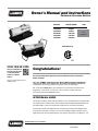
1
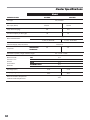
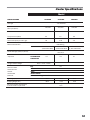
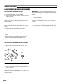
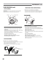
Owner’s Manual and Instructions
Tradesman Kerosene Heaters
MODELS
OUTPUT (BTUH)
CP045DK
CP075DK
CP125EK
CP175EK
CP210EK
45,000
75,000
125,000
175,000
210,000
FUEL
1-K
Kerosene
Certification by:
C
SCAN THIS QR CODE
with your smartphone or
visit http://goo.gl/nvneR
to view maintenance
videos for L.B.White
heaters.*
US
Congratulations!
You have purchased the finest kerosene portable forced air construction
heater available.
*Requires an app like QR Droid for Android or
QR Reader for iPhone.
manufacturer of heating products using state-of-the-art technology.
We, at L.B. White, thank you for your confidence in our products and welcome any
suggestions or comments you may have...call us, toll-free, at (800) 345-7200
or e-mail [email protected]
ATTENTION ALL USERS
This heater has been tested and evaluated by C.S.A. International in accordance with
the requirements of Standard UL733 and ANSI A10.10-1998, CAN/CSA B140.0-03
and CSA B140.8 - 1967 and is listed and approved as a Kerosene forced-air
construction heater with application for the temporary heating of buildings under
construction, alteration, or repair. If you are considering using this product for any
application other than its intended use, then please contact the L.B. White Co., Inc.
Quality heaters you can count on.
411 Mason St., Onalaska, WI 54650 • (800) 345-7200 • (608)783-5691 • (608) 783-6115, fax • [email protected]
150-28814
GENERAL HAZARD WARNING
Failure to comply with the precautions and instructions provided with this heater, can result in:
— Death
— Serious bodily injury or burns
— Property damage or loss from fire or explosion
— Asphyxiation due to lack of adequate air supply or carbon monoxide poisoning
— Electrical shock
Read this Owner’s Manual before installing or using this product.
Only properly-trained service people should repair or install this heater.
Save this Owner’s Manual for future use and reference.
Owner’s Manuals and replacement labels are available at no charge. See website, or for assistance, contact
L.B. White at 800-345-7200.
WARNING
Fire and Explosion Hazard
Not for home or recreational vehicle use.
Installation of this heater in a home or recreational
vehicle may result in a fire or explosion.
Fire or explosions can cause property damage or loss
of life.
FOR YOUR SAFETY
Do not store or use gasoline or other flammable vapors
and liquids in the vicinity of this or any other appliance.
WARNING
Fire and Explosion Hazard
Keep solid combustibles a safe distance away from
the heater.
Solid combustibles include wood, paper, or plastic
products, building materials and dust.
Do not use the heater in spaces which contain or may
contain volatile or airborne combustibles.
Volatile or airborne combustibles include gasoline,
solvents, paint thinner, dust particles or unknown
chemicals.
Failure to follow these instructions may result in a fire
or explosion.
Fire or explosions can lead to property damage,
personal injury or loss of life.
1
IMKFAT-GCU
Table of Contents
SECTION PAGE
General Information . . . . . . . . . . . . . . . . . . . . . . . . . . . . . . . . . . . . . . . . . . . . . . . . . . . . . . . . . . . . . . . . . . . . 2. 2
Heater Specifications . . . . . . . . . . . . . . . . . . . . . . . . . . . . . . . . . . . . . . . . . . . . . . . . . . . . . . . . . . . . . . . . . . . 3. 4
Safety Information
Hazard Definitions . . . . . . . . . . . . . . . . . . . . . . . . . . . . . . . . . . . . . . . . . . . . . . . . . . . . . . . . . . . . . . . . . . . 5. 5
General Safety Information . . . . . . . . . . . . . . . . . . . . . . . . . . . . . . . . . . . . . . . . . . . . . . . . . . . . . . . . . . . .5. 5
Installation & Assembly
Heater Specifications . . . . . . . . . . . . . . . . . . . . . . . . . . . . . . . . . . . . . . . . . . . . . . . . . . . . . . . . . . . . . . . . .7.7
Assembly . . . . . . . . . . . . . . . . . . . . . . . . . . . . . . . . . . . . . . . . . . . . . . . . . . . . . . . . . . . . . . . . . . . . . . . . . . .8.8
Operation
Overview of Heater Design . . . . . . . . . . . . . . . . . . . . . . . . . . . . . . . . . . . . . . . . . . . . . . . . . . . . . . . . . . . . 9
.9
The Safety System . . . . . . . . . . . . . . . . . . . . . . . . . . . . . . . . . . . . . . . . . . . . . . . . . . . . . . . . . . . . . . . . . . . 9. 9
Fuel Specifications . . . . . . . . . . . . . . . . . . . . . . . . . . . . . . . . . . . . . . . . . . . . . . . . . . . . . . . . . . . . . . . . . . 9
Fueling Your Heater . . . . . . . . . . . . . . . . . . . . . . . . . . . . . . . . . . . . . . . . . . . . . . . . . . . . . . . . . . . . . . . . . . 10
11
10
To Start Heater . . . . . . . . . . . . . . . . . . . . . . . . . . . . . . . . . . . . . . . . . . . . . . . . . . . . . . . . . . . . . . . . . . . . . .11
To Shutdown Heater . . . . . . . . . . . . . . . . . . . . . . . . . . . . . . . . . . . . . . . . . . . . . . . . . . . . . . . . . . . . . . . . . 10
11
10
To Restart Heater . . . . . . . . . . . . . . . . . . . . . . . . . . . . . . . . . . . . . . . . . . . . . . . . . . . . . . . . . . . . . . . . . . . .11
Extra Electrical Outlet . . . . . . . . . . . . . . . . . . . . . . . . . . . . . . . . . . . . . . . . . . . . . . . . . . . . . . . . . . . . . . . . 10
11
11
Longterm Storage of Your Heater . . . . . . . . . . . . . . . . . . . . . . . . . . . . . . . . . . . . . . . . . . . . . . . . . . . . . . .12
Maintenance
Fuel Tank . . . . . . . . . . . . . . . . . . . . . . . . . . . . . . . . . . . . . . . . . . . . . . . . . . . . . . . . . . . . . . . . . . . . . . . . . . 12
13
12
Air Intake Filter . . . . . . . . . . . . . . . . . . . . . . . . . . . . . . . . . . . . . . . . . . . . . . . . . . . . . . . . . . . . . . . . . . . . . .13
12
Air Output /Lint Filter . . . . . . . . . . . . . . . . . . . . . . . . . . . . . . . . . . . . . . . . . . . . . . . . . . . . . . . . . . . . . . . . .13
12
Rotor/Vanes, Rotor Insert . . . . . . . . . . . . . . . . . . . . . . . . . . . . . . . . . . . . . . . . . . . . . . . . . . . . . . . . . . . . .13
Fan Blades . . . . . . . . . . . . . . . . . . . . . . . . . . . . . . . . . . . . . . . . . . . . . . . . . . . . . . . . . . . . . . . . . . . . . . . . . 13
Nozzle . . . . . . . . . . . . . . . . . . . . . . . . . . . . . . . . . . . . . . . . . . . . . . . . . . . . . . . . . . . . . . . . . . . . . . . . . . . . .14
Spark Plug . . . . . . . . . . . . . . . . . . . . . . . . . . . . . . . . . . . . . . . . . . . . . . . . . . . . . . . . . . . . . . . . . . . . . . . . . .15
15
Photocell . . . . . . . . . . . . . . . . . . . . . . . . . . . . . . . . . . . . . . . . . . . . . . . . . . . . . . . . . . . . . . . . . . . . . . . . . . 15
Fuel Filter . . . . . . . . . . . . . . . . . . . . . . . . . . . . . . . . . . . . . . . . . . . . . . . . . . . . . . . . . . . . . . . . . . . . . . . . . . 16
16
Pump Pressure Adjustment . . . . . . . . . . . . . . . . . . . . . . . . . . . . . . . . . . . . . . . . . . . . . . . . . . . . . . . . . . . .16
17
Replacing Fuse . . . . . . . . . . . . . . . . . . . . . . . . . . . . . . . . . . . . . . . . . . . . . . . . . . . . . . . . . . . . . . . . . . . . . .17
Wiring Diagram . . . . . . . . . . . . . . . . . . . . . . . . . . . . . . . . . . . . . . . . . . . . . . . . . . . . . . . . . . . . . . . . . . . . . . . . 18
Troubleshooting . . . . . . . . . . . . . . . . . . . . . . . . . . . . . . . . . . . . . . . . . . . . . . . . . . . . . . . . . . . . . . . . . . . . . . . 20
Parts Identification
Parts Schematic (CP045DK & CP075DK) . . . . . . . . . . . . . . . . . . . . . . . . . . . . . . . . . . . . . . . . . . . . . . . . 21
21
Parts List (CP045DK & CP075DK) . . . . . . . . . . . . . . . . . . . . . . . . . . . . . . . . . . . . . . . . . . . . . . . . . . . . . . 22
22
23
Parts Schematic (CP125EK & CP175EK) . . . . . . . . . . . . . . . . . . . . . . . . . . . . . . . . . . . . . . . . . . . . . . . . 23
24
Parts List (CP125EK & CP175EK) . . . . . . . . . . . . . . . . . . . . . . . . . . . . . . . . . . . . . . . . . . . . . . . . . . . . . . 24
25
Parts Schematic (CP210EK) . . . . . . . . . . . . . . . . . . . . . . . . . . . . . . . . . . . . . . . . . . . . . . . . . . . . . . . . . . .25
26
Parts List (CP210EK) . . . . . . . . . . . . . . . . . . . . . . . . . . . . . . . . . . . . . . . . . . . . . . . . . . . . . . . . . . . . . . . . .26
Parts Schematic (Handles/Wheels) . . . . . . . . . . . . . . . . . . . . . . . . . . . . . . . . . . . . . . . . . . . . . . . . . . . . . 27
Warranty Information . . . . . . . . . . . . . . . . . . . . . . . . . . . . . . . . . . . . . . . . . . . . . . . . . . . . . . . . . . . . . . . . . . . 28
General Information
This Owner’s Manual includes all options and accessories
commonly used on this heater.
When calling for technical service assistance, or for other
specific information, always have model number,
configuration number and serial number available. This
information is contained on the dataplate.
This manual will instruct you in the operation and care of
your unit. Have your qualified installer review this manual
with you so that you fully understand the heater and how it
functions.
The installation, repair, and servicing of the heater
requires continuing expert training and knowledge of
kerosene heaters and should not be attempted by anyone
who is not so qualified.
Contact your local L.B. White distributor or the L.B. White
Co., Inc. for assistance, or if you have any questions about
the use of the equipment or its application.
The L.B. White Co., Inc. has a policy of continuous product
improvement. It reser ves the right to change
specifications and design without notice.
2
Heater Specifications
Model
SPECIFICATIONS
CP045DK
Fuel Type
CP075DK
1-K, Kerosene
Max Input (BTUH)
45,000
75,000
Pump Pressure (psig)
2.8
3.8
Fuel Consumption per Hour (gal)
.35
.57
Ball Bearing
Motor Characteristics
1/8 HP, 3120 RPM
1/8 HP, 3,300 RPM
Electrical Supply (Voltz/Hz/Phase)
Amp Draw
120/60/1
CONTINUOUS
OPERATION
1.6
Dimensions (Inches) Length x width x height
Minumum Safe
Distances From
Nearest
Combustible
Materials
32” x 11.8” x 16.8”
TOP
SIDES
4 ft.
4 ft.
BACK
BLOWER OUTLET
BULK FUEL STORAGE CONTAINER
4 ft.
8 ft.
25 ft.
Net Weight (Lbs.)
27.6
27.6
Shipping Weight (Lbs.)
32.0
32.0
Minimum Ambient Temperature
in Which Heater May Be Used
3
1.6
-20oF
Heater Specifications
Model
SPECIFICATIONS
CP125EK
Fuel Type
CP175EK
CP210EK
1-K, Kerosene
125,000
Max Input (BTUH)
175,000
210,000
Pump Pressure (PSIG)
5.5
7.5
8.5
Fuel Consumption per Hour (gal)
.95
1.32
1.6
Ball Bearing
Motor Characteristics
1/5HP 3455 RPM
Electrical Supply (Voltz/Hz/Phase)
Amp Draw
1/4HP 3430 RPM
1/3HP 3380 RPM
120/60/1
CONT INUOUS
2.5
3.2
3.7
OPERAT ION
Length x Width x Height
Minumum Safe
Distances From
Nearest
Combustible
Materials
36.1” x 21.5” x 24.6”
Top
Sides
Back
Blower Outlet
Bulk Fuel Storage Container
41.8” x 23.1” x 26.1”
4 ft.
4 ft.
4 ft.
8 ft.
25 ft.
Net Weight (lbs.)
58.6
65.0
66.6
Shipping Weight (lbs.)
65.9
73.9
75.4
Minimum Ambient Temperature
in which Heater may be used
-20oF
4
Safety Information
HAZARD DEFINITIONS
DANGER
Indicates an imminently hazardous situation which, if
not avoided WILL result in death or serious injury.
WARNING
Indicates a potentially hazardous situation which, if
not avoided, COULD result in death or serious injury.
CAUTION
Indicates a potentially hazardous situation which, if
not avoided, MAY result in minor or moderate injury.
GENERAL SAFETY INFORMATION
WARNING
Before using this heater, please read this USER’S
MANUAL very carefully. This USER’S MANUAL has
been designed to instruct you as to the proper
manner in which to assemble, maintain, store, and
most importantly, how to operate the heater in a
safe and efficient manner.
WARNING
Never leave the heater unattended while burning!
DANGER
Improper use of this heater can result in serious
injury or death from burns, fire, explosion, electrical
shock, and/or carbon monoxide poisoning.
5
GENERAL SAFETY INFORMATION (cont.)
WARNING
Risk of CO Poisoning!
- Use this heater only in well ventilated areas.
Provide proper ventilation. Proper ventilation air for
combustion must be provided in accordance with
OSHA 29 CFR 1926.154, Temporary Heating Devices.
ANSI A 10.10, Safety Requirements for Temporary
and Portable Space Heating Devices, or the Natural
Gas and Propane Installation Code, CAN/CSA B149.1
as appropriate.
CANADIAN RESIDENTS: Use of this heater shall be in
accor dance with authorities having juris diction and
CSA Standard B139.
NEW YORK CITY RESIDENTS: For use only at construction
sites in accordance with applicable NYC codes under
NYCFD certificate of approval #5034 and 5037
WARNING
- Never use this heater in living or sleeping areas.
- Carbon Monoxide Poisoning: Early signs of carbon
such as headaches, dizziness, and/or nausea. If you
have these symptoms, your heater may not be
working properly.
- Get fresh air at once! Have the heater serviced.
- People with breathing problems should consult a
physician before using the heater.
WARNING
Risk of Electric Shock!
- Use only the electrical power (voltage and
heater. Use only a three prong, grounded outlet and
extension cord.
- ALWAYS install the heater so that it is not directly
exposed to water spray, rain, dripping water, or wind.
- ALWAYS unplug the heater when not in use.
CALIFORNIA RESIDENTS: This heater produces carbon
monoxide, which is listed by the State of California as a
reproductive toxin under Proposition 65.
MASSACHUSETTS RESIDENTS: Massachusetts state law
prohibits the use of this heater in any building which is
used in whole or in part for human habitation. Use of this
heating device in Massachusetts requires local fire dept.
permit (M.E.L.C. 148, Section 10A).
Risk of Burns/Fire/Explosion!
- Keep all combustible materials away from this heater.
Minimum Clearances
Outlet 8 feet (250 cm)
Sides, Top and Rear 4 feet (125 cm)
- NEVER use fuels such as gasoline, benzene, paint
thinners, or other oil compounds in this heater
(RISK OF FIRE OR EXPLOSION).
be present.
operating or still hot. This heater is EXTREMELY HOT
while in operation.
- NEVER block air inlet (rear) or air outlet (front) of
heater.
- NEVER use duct work in front or at rear of heater.
- NEVER move or handle heater while still hot.
- NEVER transport heater with fuel in its tank.
- When used with optional thermostat or if equipped
with a thermostat, the heater may start at any time.
- ALWAYS locate heater on a stable and level surface.
- Use 1-K kerosene in this heater. #1 fuel oil is a
suitable substitute.
- Bulk fuel storage should be a minimum of 25 ft. from
heaters, torches, portable generators, or other sources
of ignition. All fuel storage should be in accordance
with federal, state, or local authorities having jurisdiction.
6
Installation and Assembly Instructions
HEATER SPECIFICATIONS
Introduction
Please read this USER’S MANUAL carefully. It will show you
how to assemble, maintain and operate this heater safely
features.
Consumer: Retain these instructions for future reference.
Product Features
Fan Guard
Upper Shell
Hot Air Outlet
Unpacking
1. Remove all packing items applied to heater for
shipment.
2. Remove all items from carton.
3. Check all items for shipping damage.
If heater is damaged, promptly inform dealer where you
purchased heater.
Dimensions
Handle
Pressure Gauge
Lower Shell
Cord Wrap
Fuel Tank
Side Cover
Fuel Gauge
Lamp
Fuel Cap
Thermostat Knob
(CP075DK model only)
LED Power/Reset Switch
Power Cord
6 8 10
4PRESSURE
GAUGE
12
2
0 PSI14
Figure 2.1 - Features
16 3/4"
11 3/4"
32"
Models CP045DK and CP075DK
Figure 1.1 - Heater Dimensions
Dimensions
Product Features
Handle Front
8
4 6 10
GAUGE
12
2PRESSURE
0 PSI14
H
Hot Air Outlet
Upper Shell
L
W
Pressure Gauge
Lower Shell
Figure 1.2 - Heater Dimensions
Cord Wrap
Handle Rear
Fuel Gauge
7
CP125EK
CP175EK
CP210EK
Height
24.6”
26.1”
Length
36.1”
41.8”
Width
21.5”
23.1”
Fuel Cap
Power Cord
(Piggy Back)
Side Cover
Lamp
Thermostat
Knob
Figure 2.2 - Features
Power/Reset Switch
Room Temp. Display
Installation and Assembly Instructions
ASSEMBLY
TOOLS REQUIRED
CP045DK/CP075DK
- Medium Phillips screwdriver.
on the upper housing.
2. Align the holes in upper housing with two mounting holes on the handle as shown in Figure 4.
3. Secure handle with screws provided.
4. Insert cord wrap into the rectangle holes on the supporter and align the hole on the cord wrap with
the mounting hole on the side covers shown in Figure 4.
5. Secure cord wrap with screws provided.
CP125EK/CP175EK/CP210EK
- Medium Phillips screwdriver.
- M5 open, or adjustable wrench.
1. Slide threaded axle through the rear section of the wheel support frame.
2. Slide one axle bushing on to each side of the axle. Slide one wheel on to each side of the axle.
3. Attach one cap nut on to each side of the threaded axle and tighten well.
4. Place heater on wheel support frame. Make sure the air inlet end (rear) of heater is over wheels. Align the holes on fuel
6. Align the hole on the handle (front and rear) with the mounting hole on the cord wrap.
Model
WARNING
Fire or explosion hazard!
- Do not operate heater without support frame fully
assembled to tank.
CP045DK/CP075DK
CP125EK
CP175EK
CP210EK
Wheel Support Frame
No
Yes
Yes
Yes
Wheels
No
Yes
Yes
Yes
Front-Handle
No
Yes
Yes
Yes
Rear-Handle
No
Yes
Yes
Yes
Axle
No
Yes
Yes
Yes
Cord Wrap
Yes
Yes
Yes
Yes
Hardware Kit
Yes
Yes
Yes
Yes
Handle
Yes
No
No
No
Handle
CP045DK / CP075DK Models
Screw
Handle
Wedged
Portion
Side Cover
Hardware Kit
Cord Wraps
Slit Hole
Cord Wrap
Supporter
Figure 3.1 – Component Identification
Front Guard
Screw
Figure 4 – Handle and Cord Wrap Installation CP045DK and CP075DK
CP125EK / CP175EK / CP210EK
Wheel Support Frame
Screws
Cap Nut S
Wheels
Flange Screws
Bushings
Nuts
Front Handle
Cap Nuts L
Cord Wraps
Axle
Rear Handle
8
Assembly
(cont.)
Screw
Front Handle
Flange Screw
Cord Wrap
Hot Air Outlet
Rear Handle
Cap Nut S
Fuel Tank
Flange
Air Inlet
Wheel Support Frame
Nut
Axle
Wheel Bushing
Wheel
OPERATION
Figure 5 - Assembly
Cap Nut L
Electrical System Protection: This heater’s electrical
system is protected by a fuse mounted to the PCB
Assembly that protects it and other electrical components
from damage. If your heater fails to operate, check this
Flame-Out Sensor: Utilizes a photocell to monitor the
extinguish.
FUEL SPECIFICATIONS
Figure 6 – Overview of Heater Design
OVERVIEW OF HEATER DESIGN
Fuel System: This heater is equipped with an electric air
pump that forces air through the air line connected to the
fuel intake, and then through a nozzle in the burner head.
When air passes in front of the fuel intake, it causes fuel to
rise from the tank and into the burner nozzle.
This fuel and air mixture is then sprayed into the
SureFire Ignition: The electronic ignitor sends voltage to
a specially designed spark plug. The spark plug ignites the
fuel and air mixture described above.
The Air System: The heavy duty motor turns a fan that
forces air into and around the combustion chamber. Here,
the air is heated and then forced out the front of the
heater.
THE SAFETY SYSTEM
Temperature Limit Control: This heater is equipped with
a Temperature Limit Control designed to turn the heater
off should the internal temperature rise to an unsafe level.
If this device activates and turns your heater off, it may
require service.
Once the temperature falls below the reset temperature,
you will be able to start your heater.
Model
CP045DK/CP075DK
176°F/80°C
122°F/50°C
CP125EK
230°F/110°C
194°F/90°C
CP175EK
158°F/70°C
194°F/90°C
104°F/40°C
140°F/60°C
CP210EK
9
Internal Shut-off
Reset Temp.
Temp.+/-10 Degrees +/-10 Degrees
KEROSENE (1-K)
For optimal performance of this heater, it is strongly
suggested that 1-K kero sene be used. 1-K kerosene has
as sulfur, which can cause a rotten egg odor during the
operation of the heater. However, #1 or #2 fuel oil (diesel
fuel) may also be used if 1-K kerosene is not available. Be
advised that these fuels do not burn as clean as 1-K
kerosene, and care should be taken to provide more
fresh air ventilation to accommodate any added
contaminants that may be added to the heated space.
WARNING
Fire or explosion hazard!
- Kerosene should only be stored in a blue container
that is clearly marked “kerosene”. Never store
kero sene in a red container. Red is associated with
gasoline.
- NEVER store kerosene in the living space. Kerosene
should be stored in a well ventilated area outside
the living area.
- NEVER use fuel such as gasoline, benzene, alcohol,
white gas, camp stove fuel, paint thinners, or other
oil compounds in this heater (THESE ARE VOLATILE
FUELS THAT CAN CAUSE A FIRE OR EXPLOSION).
- NEVER store kerosene in direct sunlight or near a
source of heat.
- NEVER use kerosene that has been stored from one
season to the next. Kerosene deteriorates over time.
OLD KEROSENE WILL NOT BURN PROPERLY IN THIS
HEATER.
- Use 1-K kerosene in this heater. #1 fuel is a suitable
substitute.
OPERATION (cont.)
FUELING YOUR HEATER
tank outdoors.
TO SHUT DOWN HEATER
Turn switch to “OFF” and unplug power cord.
Model CP045DK
Model CP075DK
Lamp
Lamp
WARNING
Fire and explosion hazard!
still hot.
IMPORTANT : REGARDING FIRST IGNITION OF
be done OUTDOORS. This allows the oils, etc., used
in manufacturing heater to be burned off outside.
Power/Reset Switch
- Extension Cord Wire Size Requirements:
- 6 to 100 feet (1.8 to 30.53 meters) long, use 16
AWG conductor.
- 101 to 200 feet (30.8 to 61 meters) long, use 14
AWG conductor.
NO THERMOSTAT ON 45
4. Turn thermostat control knob to desired setting and
push power switch to “ON” position. Power lamp will
light and heater will start.
NOTE: Room Temp. display indicates as following:
- When room temp. is less than 0ºF: “lo”.
- When room temp. is between 0ºF and 99ºF:
“Temp. is Displayed”
- When room temp is greater than 99ºF: “Hi”
If heater does not start, the thermostat setting
may be too low. Turn THERMOSTAT CONTROL
KNOB to higher position to start heater. If heater
still does not start, turn power switch to “OFF”
and then to “ON” position (See Figure 7.1 &7.2)
If heater still does not start, see Troubleshooting
on page 18.
Thermostat Control Knob
Figure 7.1 - Controls
Model CP125EK, CP175EK, CP210EK
Lamp
Room Temp. Display
TO START HEATER
1. Fill fuel tank with kerosene or No. 1 fuel oil.
2. Attach fuel cap.
3. Plug power cord into three prong, grounded extension
cord. Extension cord must be at least six feet long.
Power/Reset
Switch
Power/Reset
Switch
Thermostat
Control Knob
Figure 7.1 - Controls
TO RESTART HEATER
1. Wait 10 seconds after stopping heater.
2. Repeat steps under, “TO START HEATER.”
PIGGYBACK POWER CORD
Cover
Electric Outlet
Figure 7.2 - Controls
WARNING
SHOCK HAZARD!
• Always cover electric outlet when not in use.
Don’t plug and use an appliance of more than
5A current in this outlet.
NOTE: The major electrical components of this
heater are protected by a safety fuse mounted to
the PCB board. If your heater fails to start, check
should also check your power source to insure
that proper voltage and frequency are being
supplied to the heater.
10
OPERATION (cont.)
LONG-TERM STORAGE OF YOUR HEATER
FUEL TANK DRAIN CP045DK & CP075DK
1. Drain fuel tank through fuel cap opening.
2. Using a small amount of kerosene, swirl and rinse the
inside of the tank.
NEVER MIX WATER WITH KEROSENE, as it will cause rust
inside the tank. Pour the kerosene out, making sure that
you remove it all.
IMPORTANT: Do not store kerosene over summer for use
during next heating season. Using old fuel may damage
heater.
3. Reinstall fuel cap. Properly dispose of old and
dirty fuel.
- Make sure storage place is free of dust and corrosive
fumes.
- Store the heater in the original box with the original
packing material and keep USER’S MANUAL with
heater.
FUEL TANK DRAIN CP125EK & CP175EK & CP210EK
1. Remove drain bolt from bottom of fuel tank . See
Figure 9.
Seal
Seal
Fuel
Bolt
FuelDrain
Drain
Bolt
Figure 9 – Drain Plug Removal
1. Using a small amount of kerosene, swirl and rinse the
inside of the tank.
NEVER MIX WATER WITH KEROSENE, as it will cause rust
inside the tank. Pour the kerosene out, making sure that
you remove it all.
11
IMPORTANT: Do not store kerosene over summer for use
during next heating season. Using old fuel may damage
heater.
3. Tighten drain bolt firmly into the tank, otherwise it will
not seal completely.
- Make sure storage place is free of dust and corrosive
fumes.
- Store the heater in the original box with the original
packing material and keep USER’S MANUAL with heater.
MAINTENANCE
USE ORIGINAL EQUIPMENT REPLACE MENT PARTS. Use of third-party or other alternate components will void warranty and
may cause unsafe operating conditions.
WARNING
Fire or explosion hazard!
•Never service heater while it is plugged in or while hot!
REPLACE EVERY 500 HOURS OF OPERATION OR ONCE A
YEAR
- Remove upper shell and fan guard (See Air Intake Filter
Figure 10).
- Turn air pressure gauge counter-clockwise and remove.
screwdriver.
FUEL TANK
FLUSH EVERY 200 HOURS OF OPERATION OR AS NEEDED
(See Longterm Storage, page 11).
AIR INTAKE FILTER
Screw
- Reinstall fan guard and upper shell.
PUMP SERVICING
Upper Shell
Air Intake Filter
●PUMP ROTOR
Pump Body
Screw
Fan Guard
Vane
End Pump Cover
Rotor Insert
Figure 10 - Air Filter Access
WASH AND DRY WITH SOAP AND WATER EVERY 500 HOURS
OF OPERATION, OR AS NEEDED.
- Remove screws along each side of heater using medium
Phillips screwdriver.
- Lift off upper shell.
- Remove fan guard.
- Reinstall fan guard and upper shell.
AIR OUTPUT FILTER, LINT FILTER
Air Output Filter
End Filter Cover
Screw
Screw
Rotor
Figure 12 - Rotor Pump Assembly
REPLACE IF CHIPPED, CRACKED OR AS NEEDED
- Remove upper shell and fan guard (See Air Intake
Filter Figure 10).
- Turn air pressure gauge counter-clockwise and
remove.
Phillips Screwdriver (See Air Output Filter, Lint Filter
Figure 11).
- Remove end pump cover screws using a 5/16”
(8mm) nut driver/socket.
- Replace rotor, all 4 vanes and plastic rotor insert. All
of these components must be replaced at the same
time.
Lint Filter
Air Pressure Gauge
Figure 11 - Filter Assembly
Air Intake Filter
12
MAINTENANCE (cont.)
PUMP SERVICING (cont.)
●END FILTER COVER & GASKET(LEAKING)
●ROTOR GAPPING
IMPORTANT: The newly inserted rotor must be gapped
properly before you reinstall the end pump cover.
Rotor Gap
Pump Body Screw
REPLACE IF SPLIT,CRACKED OR AS NEEDED.
- Replace End filter cover.(See Air output filter,page 12)
- Replace Air ouput filter.(See Air output filter,page 12)
FAN BLADES
Set Screw
Flush
Motor Shaft
Fan Blade
Motor
Rotor
Pump Body
Figure 15 - Fan Assembly
Figure 13 - Rotor Gapping
- Slightly loosen the pump body screws using a medium
screw driver.
- Position pump body to set rotor gap to .003’’~.004’’ at top
dead center and retighten pump body screws.
- Verify the gap using calipers, a micrometer or a dollar bill.
- Reinstall the end pump cover.
- Reinstall air output filter and lint filter.
- Reinstall end filter cover and air pressure gauge.
- Reinstall fan guard and upper shell.
●AIR LINE (LEAKING)
REPLACE IF SPLIT,CRACKED OR AS NEEDED.
- Remove air line from air line fitting (See Figure 14) and from
nozzle adaptor.(See Nozzle, page 14)
- Reinstall Air line to air line fitting and nozzle adaptor.
Air Line Fitting
Gasket
Air Outfilter Filter
End Filter Cover
Air Line
Air Line
Figure 14 - Check Air leaks around Pump.
13
CLEAN EVERY SEASON OR AS NEEDED
- Remove upper shell (See Air Intake Filter Figure 10).
- Use M6 Allen wrench to loosen set screw which holds fan
blade to motor shaft.
- Slip fan blade off motor shaft.
- Clean fan blade using soft cloth moistened with kerosene
or solvent.
- Dry fan blade thoroughly.
- Reinstall fan blade to motor shaft.
- Place fan blade hub flush with end of motor shaft.
- Place set screw on flat of shaft.
- Tighten screw firmly (40-50 inch-pounds/4.5-5.6 N-m).
Reinstall upper shell.
MAINTENANCE (cont.)
NOZZLE
Combustion Chamber
Screw
Ignitor Wire
Combustion Chamber
Screw
Ignitor Wire
Spark Plug
Spark Plug
Nozzle Adaptor
Nozzle Adaptor
Burner Head
Fuel Line
Bracket-Burner
Air Line
Air Line
Nozzle Face
Fuel Line
Nozzle Face
Nozzle Adaptor
Nozzle
Nozzle Adaptor
Nozzle Adaptor
Nozzle
Nozzle Adaptor
Figure 16 – Nozzle Replacement For Models CP045DK-CP175EK
Figure 17 – Nozzle Replacement CP210EK
CLEAN NOZZLE AS NEEDED
(For Models CP045DK - CP175EK only)
- Remove upper shell (See Air Intake Filter, page 12).
- Remove fan blade (See Fan Blades).
- Remove fuel and air line hoses from nozzle adaptor.
- Remove ignitor wire from spark plug.
- Remove spark plug from nozzle adaptor using medium
phillips screwdriver.
- Turn nozzle adaptor 1/9 turn(40°) to counter clock wise
and pull toward motor to remove. (See Figure 16)
- Place plastic hex-body into vise and lightly tighten.
- Carefully remove nozzle from burner head using 5/8”
socket wrench.
- Blow compressed air through face of nozzle.
(this will remove any dirty in nozzle)
- Reinstall nozzle into nozzle adaptor until nozzle seats.
Tighten 1/3 turn more using 5/8” socket wrench.
(40~45 inch-pounds)
- Reinstall nozzle adaptor to burner head.
- Reinstall spark plug to nozzle adaptor.
- Attach ignitor wire to spark plug.
- Attach fuel and air line hoses to nozzle adaptor.
- Reinstall fan blade and upper shell.
(For Model CP210EK Only)
- Remove upper shell (See Air Intake Filter, page 12).
- Remove fan blade (See Fan Blades, page 13).
- Remove fuel and air line hoses from nozzle adaptor.
- Remove ignitor wire from spark plug.
- Remove spark plug from nozzle adaptor using medium
phillips screwdriver.
- Turn nozzle adaptor 1/8 turn (45°) to counter clock wise
and pull toward motor to remove. (See Figure 17)
- Place plastic hex-body into vise and lightly tighten.
- Carefully remove nozzle from adaptor-nozzle using 5/8”
socket wrench.
- Blow compressed air through face of nozzle.
(this will remove any dirt in nozzle)
- Reinstall nozzle into nozzle adaptor until nozzle seats
Tighten 1/3 turn more using 5/8” socket wrench
(40~45 inch-pounds)
- Reinstall nozzle adaptor to burner bracket
- Reinstall spark plug to nozzle adaptor.
- Attach ignitor wire to spark plug.
- Attach fuel and air line hoses to nozzle adaptor.
- Reinstall fan blade and upper shell.
14
MAINTENANCE (cont.)
SPARK PLUG
PHOTOCELL
CLEAN AND REGAP EVERY 600 HOURS OF OPERATION OR
REPLACE AS NEEDED.
Screw
Side Cover
Power
Switch
Spark Plug
GAP
Ignitor Wire
Nozzle Adaptor
Spark Plug
Screw Switch
Wires
PhotocellWire
Bracket
Photocell
Lens
Install Photocell
Incorrect
Correct
Figure 18 – Spark Plug Replacement
(For Models CP045DK-CP175EK)
- Remove upper shell (See Air Intake Filter, page 12).
- Remove fan (See Fan Blades, page 13).
- Remove ignitor wire from spark plug.
- Remove spark plug from nozzle adaptor using
medium phillips screwdriver.
- Clean and regap spark plug electrodes to 3.5mm gap.
- Reinstall spark plug to nozzle adaptor.
- Attach ignitor wire to spark plug.
- Reinstall fan and upper shell.
Nozzle Adaptor
GAP
Spark Plug
Screw
Spark Plug
Ignitor Wire
Figure 19 – Spark Plug Replacement
(For Model CP210EK only)
- Remove upper shell (See Air Intake Filter, page 12).
- Remove fan (See Fan Blades, page 13).
- Remove ignitor wire from spark plug.
- Remove spark plug from nozzle adaptor using
mediumphillips screwdriver.
- Clean and regap spark plug electrodes to 3.5mm gap.
- Reinstall spark plug to nozzle adaptor.
- Attach ignitor wire to spark plug.
- Reinstall fan and upper shell.
15
Figure 20 – Photocell Replacement
CLEAN PHOTOCELL ANNUALLY OR AS NEEDED.
- Remove upper shell (See Air Intake Filter, page 12)
- Remove fan (See Fan Blades, page 13)
- Remove photocell from its mounting bracket.
- Clean photocell lens with cotton swab.
TO REPLACE: Remove side cover near power switch.
- Disconnect wires from power switch and remove
side cover.
- Disconnect wires from circuit board and remove
photocell.
- Install new photocell and attach wires to circuit board
- Replace switch wires to power switch and side cover.
- Replace fan and upper shell.
MAINTENANCE (cont.)
FUEL FILTER
PUMP PRESSURE ADJUSTMENT
CLEAN OR REPLACE TWICE PER HEATING SEASON OR AS
NEEDED.
Fuel Filter
Fuel Line
Switch Wires
Flat blade
Screwdriver
Pressure Gauge
Screw
Side Cover
Power Switch
Figure 21 – Fuel Filter Replacement
- Remove side cover screws using medium Phillips
screwdriver.
- Disconnect switch wires from power switch and remove
side cover.
Relief Valve
Figure 22 – Adjusting Pump Pressure
- Start heater (See “Operation”, page 9).
- Allow motor to reach full speed.
- Reinstall side cover.
- Turn relief valve clockwise to increase pressure.
- Turn relief valve counterclockwise to decrease
pressure.
- Set pump pressure to correct pressure for each
model.
- Stop heater (see “Operation”, page 9).
Model
Pump Pressure
CP045DK
CP075DK
2.8 PSI
3.8 PSI
CP125EK
5.5 PSI
CP175EK
7.5 PSI
CP210EK
8.5 PSI
NOTE: USE ONLY ORIGINAL EQUIPMENT
REPLACEMENT PARTS. Use of alternate or third party
components will void warranty and may cause an
unsafe operating condition.
16
MAINTENANCE (cont.)
REPLACING FUSE
NOTE: The heater is fuse protected. If your heater fails to ignite, DO NOT
RETURN YOUR HEATER TO THE STORE.
Please follow the simple instructions below to inspect and change the fuse.
- Unplug heater.
- Remove side cover screws using medium Phillips screwdriver.
Fuse Holder
Fuse
WARNING
Burn hazard!
•SHOCK HAZARD. To prevent presonal injury, unplug the
power cord before replacing fuse.
- Remove fuse from fuse holder (See Figure 23).
- Replace fuse with enclosed fuse.
- Replace switch wires to power switch.
- Replace side cover.
NOTE:
Model : CP075DK
Side Cover
Power
Switch
Screw
Switch
Wires
Fuse
Fuse Holder
Model : CP045DK
Fuse Holder
Fuse
Figure 23 – Replacing Fuse
17
WIRING DIAGRAM
CONTROL PCB
DISPLAY PCB
BLACK SPARK PLUG
RED
POWER LAMP
(LED)
CN3
CN1
IGNITOR
RED
BLACK
2P
CN1
ORANGE
CN7
BLACK
PUMP
MOTOR WHITE
RED
CAPACITOR
GREEN
15uF/230VAC
PW-W/H
EARTH
PW-BLK
CN2
BLACK
POWER
SWITCH
POWER
PLUG
AC120V
60Hz
BLACK
PHOTO CELL
WHITE
BLACK
BLACK
BLACK
GREEN
LIMIT
CONTROL
FUSE
8A/125VAC
WHITE
EARTH
Figure 24 - Wiring Diagram Model CP045DK
CONTROL PCB
BLACK SPARK PLUG
RED
CN4
POWER LAMP
(LED)
RED
IGNITOR
BLACK
ORANGE
CN3
ROOM
SENSOR
THERMOSTAT
(TEMP. CONTROL)
CN6
CN5
RED
BLACK
PUMP
MOTOR WHITE
GREEN
CN2(AC2)/
WHT
CN1(AC1)/
BLK
CAPACITOR
15uF/230VAC
EARTH
AC120V
60Hz
POWER
PLUG
BLACK
POWER
SWITCH
BLACK
GREEN
BLACK
LIMIT
CONTROL
WHITE
PHOTO
CELL
BLACK
BLACK
FUSE
8A/125VAC
WHITE
EARTH
Figure 25 - Wiring Diagram Model CP075DK
18
WIRING DIAGRAM
CONTROL PCB
BLACK SPARK PLUG
RED
CN4
POWER LAMP
(LED)
RED
BLACK
ORANGE
CN3
ROOM
SENSOR
THERMOSTAT
(TEMP. CONTROL)
CN6
CN5
RED
AC120V
60Hz
POWER
PLUG
CN2(AC2)/
WHT
CN1(AC1)/
BLK
EARTH
BLACK
GREEN
BLACK
LIMIT
CONTROL
WHITE
EARTH
Figure 26 – Wiring Diagram Models CP125EK, CP175EK, CP210EK
19
FUSE
8A/125VAC
WHITE
BLACK
BLACK
POWER
SWITCH
BLACK
PUMP
MOTOR WHITE
GREEN
BLACK
PHOTO
CELL
IGNITOR
CAPACITOR
20uF/350VAC
Troubleshooting
Symptom
Heater ignites but MAIN PCB
assembly shuts heater off after a
short period of time. (Indicator
display indicates “E1”)
Possible (Cause(s))
Corrective Action
1. Wrong pump pressure
2. Dirty air output, air Intake or lint lilter
3. Dirty fuel filter
4. Dirt in nozzle
5. Dirty photocell lens
6. Photocell assembly not properly Installed (not
1. See Pump Pressure Adjustment, page 16
2. See Air Output, Air Intake and Lint Filters, page 13
3. See Fuel Filter, page 16
4. See Nozzle, page 14
5. Clean Photocell Lens, page 15
6. Make sure photocell boot is properly seated in
bracket, Page 15
7. Check electrical components. See Wiring Diagrams,
page 18
8. Replace Photocell, page 15
9. Check for cracks in end filter cover.
Replace if cracked,page 13
10. Check rotor & vane condition.
Replace if chipped,cracked,page 12
11. Check air line for splits/cracks.
Replace if splited,cracked,page 13
12. Check air leaks around the pump area,page 13
7. Bad electrical connection between photocell and
MAIN PCB assembly.
8. Defective photocell
9. Cracks in end filter cover.
10. Defective rotor& vane.
11. Splits/cracks on air line.
12. Air leaks around the pump area.
Heater will not ignite but motor
runs for a short period of time.
room temp. display indicates
“E1”)
1. No fuel in tank
2. Wrong pump pressure
3. Carbon deposits on spark plug and/or improper
gap
5. Dirt in nozzle
6. Water in fuel tank
7. Bad electrical connection between igniter and
MAIN PCB Assembly
8. Igniter wire is not attached to spark plug
Fan does not turn when heater is
plugged in and power switch was
in the “ON” position. (Indicator
room temp. display indicates “E2”)
1. Fill tank with kerosene
2. See Pump Pressure Adjustment, page 16
3. See Spark Plug, page 15
4. See Fuel Filter, page 16
5. See Nozzle, page 14
6. Flush fuel tank with clean kerosene, page 12
7. Check electrical components. See Wiring Diagram,
page 18
8. Attach igniter to spark plug. See Spark Plug, page 15
1. Thermostat setting is too low
2. Bad electrical connection between motor and MAIN
PCB Assembly
3. Jammed/shattered rotor
1. Turn thermostat control knob to a higher setting
2. Check electrical connections. See Wiring Diagram, page 18
1. Sensor failure
1. Replace sensor. See Wiring Diagram, page 18
1. Thermostat switch failure
2. Temperature limit safety device is overheated
3. No electrical power
4. Blown fuse
5. Bad electrical connection between temperature
limit safety device and PCB board
1. Replace MAIN PCB
2. Turn power switch to “OFF” and allow to cool (about 10 min.)
3. Check to insure heater cord and extension cord are
plugged in. Check power supply
4. Replace safety fuse in PCB board. See Replacing
Fuse, page 17
5. Check electrical connections. See Wiring Diagrams page 18
3. See Servicing Pump, page 12.
room temp. display indicates “E3”)
Heater will not turn-on (Indicator
Lamp is off)
20
Parts Identification
PARTS SCHEMATIC (CP045DK, CP075DK)
For Repair Parts,
call 1-800-345-7200
Please provide following information:
-Model number
-Serial number (if any)
-Part description and number as shown in parts list
14-4
26
24
23
14-1
14-2
14-3
16
11
13
15
14
17
12
17-2
22
25
17-4
17-7
17-8
17-1
17-3
21
18
20
17-9
19
8
10
17-5
17-6
1
6
9
3
2
7
4
5
Figure 27– Repair Parts Illustration for Portable Oil-Fired Heaters Models CP045DK, CP075DK
21
Parts List (CP045DK, CP075DK)
Reference
Number Description
Part Number for Models:
CP045DK
CP075DK
1 Fuel Tank Assembly
572701
572700
572453
572454
2 Fuel Gauge
3 Fuel Cap
----------573414---------4 Panel Right Side Assembly
572920
572919
5 Power Switch
----------572251 ---------6 Display P.C.B. Assembly
572162
----572159
7 Power Cord
----------------8 Panel Left Side Assembly
572254
572257
9 Ignition Transformer
----------573399---------10 Fuel Filter
---------572154---------572698
572699
11 Combustion Chamber
12 Photocell Bracket
572184
572185
13 Photocell Assembly
----------572186---------14 Burner Head Assembly
572901
572903
14-1
Burner Head
----------572692---------14-2
Nozzle Assembly
572192
572193
14-3
Nozzle Adaptor
----------572652--------14-4
Spark Plug Assembly
----------572200-------------------572265---------15 Fan Guard
16 Fan Assembly
572232
572233
----------572651---------17 Motor and Pump Assembly
----------572694---------17-1
Motor
----------572650---------17-2
Capacitor
17-3
Motor Support
----------572695---------17-4
Pump Body
----------572223---------17-5
Filter Kit*
----------572227---------Pump Adjustment Kit***
----------572230---------17-6
17-7
Rotor Kit**
----------572225---------17-8
Pump Cover
----------572696---------17-9
Filter Cover
----------572229---------18 Pressure Gauge
----------572231---------19 Main P.C.B. Assembly
572653
573403
----------572691---------20 Air/Fuel Lines
21 Clip Nut (8-Pack)
----------572284-------------------572726--------22 Temperature Limit Assembly
23 Screw (12-Pack)
----------572282-------------------572697--------24 Upper Shell
----------572693---------25 Lower Shell
26 Front Guard
----------572270---------Fuse
----------572447-------------------572324---------Hardware Kit
Pump/Filter Cover Screws (10-Pack)
----------572283---------Filter Kit* - Includes Intake, Outlet, and Lint Filter
Rotor Kit** - Include Rotor, Blades, and Insert
Pump Adjustment Kit*** - Includes Ball Spring and Adjusting Screw
22
Parts Identification
PARTS SCHEMATIC (CP125EK & CP175EK)
For Repair Parts,
call 1-800-345-7200
Please provide following information:
-Model number
-Serial number (if any)
-Part description and number as shown in parts list
14-4
24
23
14-1
14-2
14-3
11
16
13
17-2
17
12
17-4
17-5
25
22
17-8
17-9
17-1
17-3
15
14
21
17-10
18
20
10
17-6
17-7
19
1
8
2
9
3
7
4
6
5
Figure 28– Repair Parts Illustration for Portable Oil-Fired Heaters Models CP125EK, CP175EK
23
PARTS LIST (CP125EK & CP175EK)
Reference
Number
Description
CP125EK
Part Number for Models:
CP175EK
1 Fuel Tank Assembly
572707
572714
2 Fuel Gauge
572455
572456
----------573414---------3 Fuel Cap
4 Panel Right Side Assembly
572925
572924
5 Power Switch
----------572251---------6 Drain Plug
----------572450---------7 Power Cord
----------573404---------8 Panel Left Side Assembly
573406
573407
----------573399---------9 Ignition Transformer
10 Fuel Filter
----------572155---------11 Combustion Chamber
572706
572713
----------572185---------12 Photocell Bracket
----------572186---------13 Photocell Assembly
14 Burner Head Assembly
572897
572898
14-1
Burner Head
572705
572711
14-2
Nozzle Assembly
572194
572195
-----------572658----------14-3
Nozzle Adaptor
14-4
Spark Plug Assembly
----------572201---------572266
572907
15 Fan Guard
16 Fan Assembly
572234
572235
17 Motor and Pump Assembly
572659
572660
17-1
Motor
572709
572716
17-2
Capacitor
-----------572655----------17-3
Motor Support
---------572703--------17-4
Capacitor Holder
---------572702--------17-5
Pump Body
----------572223---------17-6
Filter Kit*
----------572227---------17-7
Pump Adjustment Kit***
----------572230---------17-8
Rotor Kit**
----------572225---------17-9
Pump Cover
---------572696--------17-10 Filter Cover
----------572229---------18 Pressure Gauge
----------572231---------19 Main P.C.B. Assembly
-----------573402 ----------20 Air/Fuel Lines
572704
572712
21 Clip Nut (8-Pack)
----------572284---------22 Temperature Limit Assembly
572727
572933
23 Screw (12-Pack)
----------572282---------24 Upper Shell
572710
572717
25 Lower Shell
572708
572715
Fuse
----------572447---------Hardware Kit
-----------572928----------Pump/Filter Cover Screws (10-Pack)
----------572283---------Filter Kit* - Includes Intake, Outlet, and Lint Filter
Rotor Kit** - Include Rotor, Blades, and Insert
Pump Adjustment Kit*** - Includes Ball Spring and Adjusting Screw
24
Parts Identification
PARTS SCHEMATIC (CP210EK)
For Repair Parts,
call 1-800-345-7200
Please provide following information:
-Model number
-Serial number (if any)
-Part description and number as shown in parts list
15-4
25
20
15-2
15-1
15-3
11
17-4
13
17-3
17-6
17-7
19
16
17
12
17-5
17-1
17-2
15
14
24
17-9
23
18
22
17-8
10
17-10
21
9
1
8
2
3
7
4
6
5
Figure 29 – Repair Parts Illustration for Portable Oil-Fired Heater (Model CP210EK)
25
PARTS LIST (CP210EK)
Reference
Number
1
2
3
4
5
6
7
8
9
10
11
12
13
14
15
15-1
15-2
15-3
15-4
16
17
17-1
17-2
17-3
17-4
17-5
17-6
17-7
17-8
17-9
17-10
18
19
20
21
22
23
24
25
Description
Part Number for Models:
CP210EK
Fuel Tank Assembly
Fuel Gauge
Fuel Cap
Panel Right Side Assembly
Power Switch
Drain Plug
Power Cord
Panel Left Side Assembly
Ignition Transformer
Fuel Filter Assembly
Combustion Chamber
Photocell Bracket
Photocell Assembly
Temperature Limit Assembly
Burner Assembly
Nozzle Assembly
Bracket Burner
Nozzle Adapter
Spark Plug Assembly
Fan Assembly
Motor and Pump Assembly
Motor
Motor Support
Capacitor Holder
Capacitor
Pump Body
Rotor Kit**
Pump Cover
Filter Kit*
Filter Cover
Pump Adjustment Kit***
Pressure Gauge
Fan Guard
Screw (12-Pack)
Main P.C.B. Assembly
Air/Fuel Lines
Clip Nut (8-Pack)
Lower Shell
Upper Shell
Hardware Kit
Fuse
Pump/Filter Cover Screws (10-Pack)
572721
572457
573414
572923
572251
572450
573404
573407
573399
572155
572720
572185
572186
572725
572899
572196
572719
572662
572202
572235
572661
572723
572703
572702
572655
572224
572226
572696
572227
572229
572230
572231
572267
572282
573402
572718
572284
572722
572724
572928
572447
572283
Filter Kit* - Includes Intake, Outlet, and Lint Filter
Rotor Kit** - Include Rotor, Blades, and Insert
Pump Adjustment Kit*** - Includes Ball Spring and Adjusting Screw
26
Parts Identification
PARTS SCHEMATIC HANDLES & WHEELS
For Repair Parts,
call 1-800-345-7200
Please provide following information:
-Model number
-Serial number (if any)
-Part description and number as shown in parts list
1
4
5 HARDWARE KIT
2
3
Figure 30– Repair Parts Illustration for Models CP125EK, CP175EK, CP210EK
Replacement Parts List for Models CP125EK, CP175EK, CP210EK
27
Part No. for Models:
CP175EK & CP210EK
CP125EK
Ref.
No.
Description
1
2
3
4
5
Upper Handle Kit
572927
572926
Wheel Support/Axle Kit 572273
572277
Wheels Kit
576416
Cordwarp Kit
572275
Hardware Kit
572928
Warranty Policy
EQUIPMENT
L.B. White Co., Inc. warrants that the component parts of its
heater are free from defects in material and workmanship,
when properly installed, operated, and maintained in
accordance with the Owner’s Manual safety guides and
labels contained with each unit. If, within 24 months from
the date of purchase by the end user, any component is
found to be defective, L.B. White Co., Inc. will at its option,
repair or replace the defective part or heater, with a new
part or heater, F.O.B., Onalaska, Wisconsin, USA.
Registering your product online with L.B. White will
automatically qualify a unit and its component parts for
warranty consideration. If a product has not been registered
with L.B.White, a copy of the bill of sale will be required to
establish warranty qualification. If neither is available, the
warranty period will be 24 months from date of shipment
from L.B.White.
PARTS
L.B. White Co., Inc. warrants that replacement parts
purchased from the company and used on the appropriate
L. B. White heater are free from defects both in material and
workmanship for 24 months from the date of purchase by
the end user. Warranty is automatic if a component is found
defective within 24 months of the date code marked on the
part. If the defect occurs more than 24 months later than
the date code but within 24 months from the date of
purchase by the end user, a copy of a bill of sale will be
required to establish warranty qualification.
The warranty set forth above is the exclusive warranty
provided by L.B. White, and all other warranties, including
any implied warranties or merchantability or fitness for a
particular purpose, are expressly disclaimed. In the event
any implied warranty is not hereby effectively disclaimed
due to operation of law, such implied warranty is limited in
duration to the duration of the applicable warranty stated
above. The remedies set forth above are the sole and
exclusive remedies available hereunder. L.B. White will not
be liable for any incidental or consequential damages
directly or indirectly related to the sale, handling or use of
the heater, and in any event L.B. White's liability in
connection with the heater, including for claims based on
negligence or strict liability, is limited to the purchase price.
Some states do not allow limitations on how long an implied
warranty lasts, so the above limitation may not apply to you.
Some states do not allow the exclusion or limitation of
incidental or consequential damages, so the above
limitation or exclusion may not apply to you. This warranty
gives you specific legal rights, and you may also have other
rights which vary from state to state.
To register your product and ensure full warranty, go to http://www.lbwhite.com/product-registration.
Please have the serial number(s) and model(s) handy for the products you are registering.
Replacement Parts and Service
Contact your local L.B. White dealer for replacement parts and service. You may also call L.B White Co., Inc.
at (800)345-7200 for assistance or email to [email protected].
Be sure that you have heater model number and configuration number when calling.
28