1
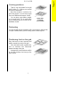
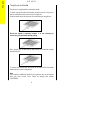
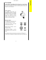
SIG 405 R
Operating
and
Installation Instructions
n
SIG 405R
u
c
iot
Introduction
nI
t
or
d
This gas appliance has been designed and manufactured to all the
necessary British Standards. It also carries the C.E. mark. The
appliance complies with European Council Directive 90/396/EEC.
It is important that you understand how to use and care for the appliance
properly before you use it for the first time.
We have written this booklet with your safety in mind. Read the booklet
thoroughly before you use the appliance. Keep the booklet in a safe
place so that anyone who uses the appliance can read it. Pass the
booklet on with the appliance if you give or sell it to someone else.
For your safety
This appliance is not intended to be operated by means of an
external timer or separate remote control system.
The appliance is designed for domestic use to cook food. You
must not use it for any other purpose. It is not designed for
commercial use.
Keep children, babies and toddlers away from the appliance at all
times.
The installation instructions tell you how and where it can be
fitted. If the appliance is already installed you must make sure
that all instructions have been followed. If you are in any doubt
ask a registered person. More details on installation on page 28.
We have included several drawings to show the right and wrong way
of doing things.
The right way will have a smiling face by it.
A sad face shows something is wrong.
RATING PLATE
This is situated on the lower front frame of the appliance and can be
seen upon opening the door. Alternatively the rating plate may also be
found on the back or top of some models (Where applicable). Do not
remove the rating plate from the appliance as this may invalidate
the guarantee.
2
Contents
Contents
SIG 405R
Page
Lighting the appliance
4
The grill
6
The hotplate
9
The oven
12
Oven cooking chart
15
The electronic minute minder
18
Slow cooking
22
Care and cleaning
24
Installing the appliance
29
General information
31
What is wrong and why?
33
Servicing
35
Installation Instructions
37
Technical Data
38
Safety requirements/ventilation
39
Location of appliance
40
Installation
41
Testing
43
3
Lighting the appliance
SIG 405R
Lighting the appliance
The system works by means of an electric spark system. Details about
the plug are given on page 31.
Hotplate & Grill
To light
1. Lift up the lid. You cannot use the hotplate when the lid is down.
2. Push in the control knob and turn it to the large flame symbol
(highest setting), and press the ignition button immediately. When
the burner has lit release the button
3. Leave the grill door open when you are using the grill.
Warning: If the ignition button is not pressed immediately a build up of
gas may cause the flame to spread.
For your safety
If you close the lid of the appliance while any of the hotplate
burners are lit the gas will go out. This is because it would be
dangerous if the burners stayed on when the lid was closed.
Always use the control knob to turn off a burner. Do not use
the lid as a cut-off device. This will only cut off the gas when
the lid is closed. The gas will flow again when the lid is
opened.
Please note: If you have any trouble lighting a hotplate burner turn all
the hotplate control knobs off and make sure the hotplate burner parts
have been replaced correctly.
See page 25 for more information.
4
The oven
To light:
1 Open the oven door.
2 Push in the control knob and turn it to gas mark 9.
3 Now turn the control knob back to the gas
mark you want.
4 Wait until the burner is showing large
flames.
5 Close the oven door.
To turn off any burner
1 Push in the control knob and turn it to the off position. This is shown
by a large dot.
For your safety
When you are lighting any burner check that it has lit before you
leave the appliance.
When you are turning off a burner, do not leave the appliance until
the flame has gone out.
5
Lighting the appliance
SIG 405R
The grill
SIG 405R
The grill
The grill is a high-speed grill. The instructions below tell you how to vary
the heat setting and how to change the height of the grid to suit the food
you are cooking. You should remember to turn the food regularly.
You should not use the grill to keep food warm as it will continue to
cook the food.
Prior to using the grill
We suggest that you operate the grill for approximately 5 - 10 mins to
burn off any residue from the surface. During this period a slight odour
may be emitted, it is therefore advisable to open a window for
ventilation.
When you first operate the grill you may hear some sounds as the
burner heats up, this is quite normal and is not a fault on the appliance.
For your safety
The grill pan and handle must be in place before igniting the grill.
You must keep the grill door open when the grill burner is lit.
Accessible parts may be hot when the grill is used. Young
children should be kept away.
Never cover the grill pan or grid with foil as this can lead to grill
fires.
Heat control
The grill control has two heat settings.
The
control
knob
turns
anticlockwise from 'OFF' to 'HIGH'
and then to 'LOW'. Use the high
setting for fast cooking such as toast.
Use the low setting to cook thicker
food such as chicken after you have
browned it on the high setting.
6
Cooking positions
There is only one position for the grill
shelf (Position 2). Positions are counted
from the top downwards.
Most food should be cooked on the
grid in the grill pan. You can turn the grid
over to suit different thicknesses of food.
You can place some dishes straight
on to the grill shelf. This is useful when
you are browning the top of food such as
cauliflower cheese.
Preheating
You don't usually need to preheat the grill. You may wish to preheat it for
a couple of minutes when you are cooking steak or browning food.
Positioning food on the grid
Place food such as toast, tea-cakes and
muffins towards the centre of the grid.
Place food which needs a gentle heat,
such as tomatoes and mushrooms
towards the edge of the grid.
Arrange meat, meat products and fish
to suit their thickness and how you like
them cooked.
7
The grill
SIG 405R
The grill
SIG 405R
The grill pan and handle
The grill pan is supplied with a removable handle.
To attach the handle, place the wirework under the cut out in the pan so
that the metal plate hooks over the top of the grill pan.
Slide the handle to the left and over the central bump on the grill pan.
Ensure the handle is correctly located. It is not necessary to
remove the grill pan handle during grilling.
Place the grill pan on the shelf so that the pan is positioned centrally
beneath the grill.
To remove the handle, slide the handle to the right and lift the handle
away from the cut out on the grill pan.
Note
If you require an additional handle for your grill pan, this can be ordered
from your local Service Force Centre by quoting part number
311479800\6.
8
The hotplate
You can only use the hotplate when the lid is open. If you have any
trouble lighting a hotplate burner turn all hotplate control knobs off and
make sure the hotplate burner parts have been replaced correctly. See
page 25 for more information.
Heat control
The hotplate control knobs turn
anticlockwise from 'OFF' to 'HIGH'
and then to 'LOW'. You can adjust
the heat by turning the control
between the highest and lowest
settings. These are shown as a
large and a small flame symbol.
Burner sizes
The hotplate has three burner sizes
to suit different types of cooking:
Largest burner (Rapid) - use a large
pan for food such as chips.
Medium burners (Normal) - use for
everyday cooking.
Small burner (Simmer) - use for
simmering food such as soups and
stews.
The largest pan which you should use on any burner is 230mm (9").
The base of the smallest pan should not measure less than 100mm (4").
9
The hotplate
SIG 405R
The hotplate
SIG 405R
For your safety
1
Take care to avoid burns and scalds when you
are reaching across the hotplate.
Use pans with flat bases. They are more stable
than pans which are warped.
Do not use pans with very heavy handles which
cause the pan to tip.
Put pans on the centre of the burners.
Position pan handles so they cannot be
accidentally knocked.
Take extra care when you are deep fat frying. Do
not cover the pan with a lid.
Do not leave a pan unattended. If the pan
catches fire, leave it where it is and turn off all
controls.
Place a damp cloth or a fitting lid over the pan to
smother the flames.
Never put water on the fire.
Leave the pan to cool for 30 minutes.
7
If you are using a Wok we recommend it has a flat
base as it will stand stable on the pan supports. If
you use a round based Wok with a collar support,
the collar must be of the open wire work type. A
closed collar will affect the performance of the
burner. Before you use the Wok make sure that
the collar is stable on the pan supports. Always
follow the instructions that come with the Wok.
8
Do not use the lid as a work surface or chopping
board. This could damage the glass and reduce
its strength.
10
Helpful hints
1
Keep flames under the base of pans. If
the flames lick round the sides of the
pans you are wasting gas.
2
Only heat the amount of liquid you
need. Do not overfill pans.
3
Cover pans with a lid whenever
possible. The food will heat up more
quickly and there will be less steam in
the kitchen.
4
Try cooking more than one vegetable in
the same pan, for example potatoes
and carrots.
5
Cut vegetables into smaller pieces.
This way they will cook more quickly.
6
A pressure cooker will save time and
energy.
11
The hotplate
SIG 405R
The oven
SIG 405R
The oven
Before you use the oven you should wipe it out with a damp cloth to
remove any dust.
Heat zones
There are zones of heat within the oven. The
temperature in the middle is the gas mark you
have chosen. The top of the oven is slightly
hotter and the lower shelf slightly cooler. The
base of the oven is quite a lot cooler. You can
make use of these heat zones when you are
cooking foods that need different
temperatures all at the same time.
If you are cooking more than one tray of similar items, for example
cakes or biscuits, swap the trays around during cooking. Or you can
remove the top tray when the food is cooked and move the lower tray to
the higher shelf to finish cooking.
Preheating
You do not need to preheat the oven for casseroling and so on.
Preheat the oven for baking or when you are cooking sensitive food
such as Yorkshire puddings, soufflés and yeast mixtures.
When you are cooking or reheating frozen or chilled food read the
instructions on the packaging. When you need to preheat the oven, we
recommend you do so for 20 minutes.
Oven shelves
You can slot the oven shelves into any of five
positions in the oven. Positions are counted
from the top downwards.
For safety the shelves will only pull out so far.
If you want to remove a shelf completely, pull
it forward as far as it will go, raise the front
edge and lift it out.
To put the shelf into a different position, keep the front edge raised, slot
the shelf on to the runner, lower the front edge and slide the shelf in.
12
Baking trays and dishes
For your safety
Never place cooking dishes, trays and so
on over the oven burners. This will
damage the appliance as well as the
cookware and possibly the floor covering
underneath the appliance.
Leaveaagap
gap ofof13mm
13mm(½")
(½")between
betweenallall
Leave
dishes
and
the
sides
of
the
oven
dishes and the sides of the oven sosothethe
heatcan
cancirculate
circulateproperly.
properly.
heat
DoDonotnotpush
pushdishes
dishestootoofarfarback
backasasfood
food
will
if itifoverhangs
the burner
flames.
willburn
burn
it overhangs
the burner
flames.
For the best results from the oven we recommend that you use a baking
tray which is 310mm (12") square. If you use a tray or tin which is larger
than this, you may need to turn it around during cooking.
Place single dishes on the centre of the shelf. You may need to turn
large items around during cooking.
Roasting
For best results we recommend open roasting using minimal fat or oil to
prevent splashing.
It is not necessary to cover meat or poultry or wrap food in foil when
roasting as this restricts the circulation of heat and will lead to extended
cooktimes.
If you are using a roasting bag or cover chicken breast with foil, be
prepared to allow an extra 10 - 15 minutes for each 1/2kg (1lb).
When cooking large items such as turkeys, the use of foil may be
required to prevent the breast becoming dry before the rest of the bird is
fully cooked.
13
The oven
SIG 405R
The oven
SIG 405R
Condensation
Condensation may form on the appliance. This is quite normal and
nothing to worry about. The condensation forms when heat and
moisture are present, for example during cooking. Whenever possible
try to make sure that food which contains a lot of moisture, for example
casseroles, are covered. If you do notice any condensation, wipe it up
straight away.
14
15
5
5
5
Beef
Lamb
Pork and Veal
Roasting meat:
4
4
4
Shelf
position
Medium:
Well Done:
Medium:
Well Done:
Rare:
Medium:
Well Done:
Approximate
cooking time
Oven cooking chart
30 mins. per ½ kg (1lb) and 30 mins.
35 mins. per ½ kg (1lb) and 35 mins.
25 mins. per ½ kg (1lb) and 25 mins.
30 mins. per ½ kg (1lb) and 30 mins.
20 mins. per ½ kg (1lb) and 30 mins.
25 mins. per ½ kg (1lb) and 25 mins.
30 mins. per ½ kg (1lb) and 30 mins.
Thaw frozen joints thoroughly before cooking them.
Gas
mark
Food
These instructions are for cooking in the oven after it has been pre-heated for 20 minutes.
If you are cooking more than one tray of similar items, for example cakes or biscuits, swap the trays around during cooking or you
can take the top tray out of the oven when the food is cooked and move the lower tray to the higher shelf to finish cooking.
Always leave at least one shelf position between shelves to allow heat to circulate.
The recommended shelf positions give the best results.
Put the dishes in the centre of the shelf.
You can change the gas marks and cooking times to suit your own tastes.
It is important to check that food is piping hot before serving.
Oven cooking chart
SIG 405R
Approximate
cooking time
5
4
20 mins. per ½kg (1lb) and 20 mins.
4
4
25 mins. per ½kg (1lb) and 25 mins.
4
4 or 5
15 mins. per ½kg (1lb) and 15 mins.
5
4
25 mins. per ½kg (1lb)
Cook as above but calculate weight including stuffing.
Shelf
position
Thoroughly thaw frozen joints before cooking them.
Chicken
Turkey below 4.5kg (10lbs)
over 4.5kg (10lbs)
Duck and duckling
Stuffed poultry
Gas
mark
16
4
4
4
2&4
2&4
2&4
2&4
2
2
4
5
7
4
4
Rich fruit, 180mm (7")
205 mm (8")
Madeira, 180 mm (7")
Small cakes
Scones
Victoria Sandwich
180mm (7")
205 mm (8")
4
2
Christmas Cake (8")
2
2
Cakes:
7
7
- large
- individual
Yorkshire pudding
20 - 30 mins.
20 - 35 mins.
2¼ - 2¾ hours.
2½ - 2¾ hours.
1 hour.
15 - 25 mins.
10 - 20 mins.
4 - 5 hours.
25 - 30 mins.
15 - 25 mins.
The times given above are for open roasting. If you cover with foil or a lid allow an extra 10 - 15 minutes cooking time for each ½kg (1lb)
Poultry:
Food
Oven cooking chart
SIG 405R
Plate tart (shortcrust)
Fruit pie (shortcrust)
Mince pies (flan pastry)
Shelf
position
2
2
2&4
Gas
mark
6
6
5
25 - 35 mins.
25 - 35 mins.
15 - 25 mins.
Approximate
cooking time
17
Bread 0.45 kg (1lb loaves)
0.90 kg (2 lb loaves)
Rolls and buns
Yeast mixtures:
8*
8*
8*
2
4
3
3
3
2
3
4
4
30 - 40 mins.
30 - 40 mins.
10 - 20 mins.
2 hrs. approx.
45 - 60 mins.
50 - 60 mins.
Oven cooking chart
* Note: When baking bread, cook for 10 minutes at Gas mark 8 then reduce to mark 6 for the remaining cook time.
Note: You must soak dried beans then boil them in an open pan for 15 minutes before you add them to any dish.
Milk pudding
Baked sponge pudding
Baked custard
Puddings:
To help pastry brown on the underside cook on a metal plate,or if plates are flat and have no rim underneath,place on baking tray.
Pastries:
Food
SIG 405R
The electronic minute minder
SIG 405R
THE ELECTRONIC MINUTE MINDER
1=
(-)
DECREASE CONTROL & MINUTE
MINDER
2=
(+)
INCREASE CONTROL
(
)
COOKPOT SYMBOL
1
2
The electronic minute minder can indicate the time of day, operate as a
minute minder and it can be used to time and switch off the main oven.
Please note that this is a 24 hour clock, for example 2.00pm is shown
as 14.00.
In the following pages we explain how to use the minute minder and set
the time of day. Read through them until you are familiar with the
procedure.
Fig.1
1. SET THE TIME OF DAY
When the electricity supply is first
switched ON, the display will flash 0.00.
See Fig. 1.
Press buttons (1) and (2) together.
Release buttons, 0.00 will appear in
the display as Fig. 2. Within 5
seconds press button (2), 12.00
will show in the display as Fig. 3.
Fig.2
Within 5 seconds press and hold
either button (1) to decrease or button
(2) to increase the time until the
correct time of day on the 24 hour clock
is reached, e.g.14.30. See Fig. 4.
Fig.3
Note: The increase and decrease
control buttons operate slowly at
first, and then more rapidly. They
should be pressed separately.
Fig.4
18
2 TO USE THE MINUTE MINDER
IMPORTANT
The minute minder can be used to time a set cooking period. At the end
of the cook time the minute minder will automatically switch off the main
oven if in use.
The minute minder gives an audible reminder at the end of any period of
cooking up to 23 hours and 59 minutes.
To set press button (1) and the display
will read 0. 00, see Fig. 5.
Release button (1) and press and hold
button (2). The display will count up in
one minute intervals until the interval to
be timed is reached e.g. 30 minutes,
see Fig. 6. If necessary press and hold
button (1) to achieve the correct time
interval.
Fig.5
Fig.6
The minute minder will begin to count
down once set. The time of day will
show in the display. To show the remainder of the cook time. Press
button (1).
At the end of the timed period the minute minder will click, switching the
main oven OFF if in use.
An audible signal will sound for up to 2
minutes. The Auto symbol will flash and
the cookpot symbol will go out. The
time of day will show in the display. See
Fig. 7.
Fig.7
To stop the sound press button (1). Fig.8
The display will stop flashing and show
the time of day, e.g. 15.00.
To return the timer to manual press
button (1) again. See Fig. 8. If using
the main oven it will come on again
once button (1) has been depressed. When cooking is complete
remove food and turn OFF oven temperature control.
19
The electronic minute minder
SIG 405R
The electronic minute minder
SIG 405R
3. TO CANCEL THE MINUTE MINDER
If you change your mind and want to
cancel the minute minder. Press and
release button (1). Press and hold
button (1) and the display will count
down in one minute intervals to 0. 00
See Fig. 9. Release button (1).
Fig.9
Fig.10
After a few seconds the time of day
will show in the display. See Fig. 10.
If the main oven is in use this will switch
OFF after a few seconds.
Fig.11
To reset, press buttons (1) and (2)
together. See Fig. 11.
4. THINGS TO NOTE
1. The time of day must be set before the main oven will operate.
There will be a few seconds delay before the oven switches on.
2. The minute minder function controls the main oven only and will
switch the oven OFF at the end of a timed period. This function is useful
if you want to begin cooking now and have the oven switch OFF
automatically.
3. If you have used the minute minder to time food cooking in the main
oven you will need to reset the timer by pushing button (1) before the
oven can operate again.
20
The electronic minute minder
SIG 405R
5. LOCK FEATURE - MAIN OVEN ONLY
Please read the following information with care.
TO LOCK THE OVEN USING THE TIMER
Press and hold Buttons (1) and (2) for 3
- 8 seconds. See Fig 12.
'On' will appear in the display. See Fig
13.
Press Button (2) to change the display
to 'Of'.
The key symbol (
) appears in the
display.
The oven will now not operate.
After a few seconds the time of day will
show in the display.
Wait 3 seconds before selecting another
function.
Fig.12
1
Fig.13
TO UNLOCK THE OVEN
Press and hold Buttons (1) and (2) for 3
- 8 seconds.
'Of' will appear in the display. See Fig
14.
Press Button (2) to change the display
to 'On'.
The key symbol ( ) will go out.
After a few seconds the time of day will
show in the display.
The oven can now be operated
normally.
21
Fig.14
2
Slow cooking
SIG 405R
Slow cooking
The slow cook setting gives a very low heat in the oven. It is particularly
useful when you are cooking soups, stews and casseroles because the
long slow cooking will make cheaper, tougher cuts of meat more tender.
You need to cook food at gas mark 6 for 30 minutes before you turn
the oven down to the slow cook setting. This makes sure that the
temperature of the food gets hot enough to start the food cooking.
Mark 6
Turn to S
Some foods such as pastry and biscuits are not suitable for slow
cooking because the temperature is too low.
Cover all food during cooking to prevent it from drying out. You can
uncover food for the last half hour if it is normally served golden brown.
Food preparation - slow cooking
Joints of meat and poultry
l
l
l
l
l
l
l
l
l
l
l
Do not cook meat joints over 2.7kg (6lb).
Do not cook poultry over 2kg (4lb 8oz).
Cook on the middle shelf of the oven or above.
Cook stuffing separately.
Cook for a minimum of 6 hours.
Joints of pork must only be cooked if you can ensure, by using a
meat thermometer, that an internal temperature of at least 88oC has
been reached.
For good air circulation always stand joints on a rack in a roasting tin
or casserole.
Thaw all frozen meat and poultry before cooking.
Prime cuts of meat do not benefit from slow cooking.
Remove excess fat and skin unless browned first.
Cook for 30 minutes at gas mark 6, then reduce to the slow cook
setting.
22
Soups, casseroles and stews
l
l
l
l
Do not cook casseroles over 2.7kg (6lb).
Bring to the boil on the hotplate then cook on slow cook.
Cook in the middle of the oven or above.
Cover food with a tight fitting lid or tin foil.
Vegetables
l
l
l
l
l
Cut into small pieces.
Dried beans must be pre-soaked then boiled in an open pan for 15
minutes before adding to any dish.
Place vegetables under meat in casseroles.
Cover food with a tight fitting lid or tin foil.
Cook for 30 minutes at gas mark 6, then reduce to the slow cook
setting.
Milk puddings
l
l
l
Cover the cereal with boiling water and allow to stand for 30 minutes.
Drain and make the pudding in the usual way.
Cook for 30 minutes at gas mark 6, then reduce to the slow cook
setting.
General points for slow cooking
Frozen foods
Thaw thoroughly before cooking.
Thickening
Toss meat in flour for casseroles. Alternatively blend cornflour with
water and add at the end of cooking.
Flavouring
Flavours are retained because there is little evaporation. Adjust at the
end of the cooking time.
Liquid
Reduce normal liquid quantities slightly as there is little evaporation
during cooking time.
Milk and milk products, for example cream
Add these towards the end of cooking to prevent them from curdling.
Reheating
Left over food should be cooled quickly and refrigerated.
Do Not reheat food using the slow cook setting. Reheat food
conventionally or in a microwave. Food must only be reheated once.
23
Slow cooking
SIG 405R
Care and cleaning
SIG 405R
Care and cleaning
For your safety
For hygiene and safety reasons you must keep this gas
appliance clean. A build up of fat or other foodstuff could cause
a fire.
Try to mop up spills and splashes as soon as they happen. But
be careful as parts of the appliance will be hot.
Do not use any polishes, caustic cleaners, abrasives, washing soda or
soap powder except those recommended in this booklet.
Please note: If we recommend you
use hot soapy water we mean hot
water with washing up liquid in it and
not any other cleaning product.
If you own a dishwasher please
read the operating instructions for the
machine before you wash any part of
your appliance in it.
Clean your appliance regularly using a cloth that has been wrung out
in hot soapy water. Rinse and polish it dry using a soft cloth.
When you remove parts of your appliance for cleaning do not
plunge them into water whilst they are very hot as this may damage the
finish of the parts.
The hotplate
Clean the hotplate top using a mild abrasive such as 'Cif'. Take care not
to damage the spark electrodes. If the spark electrodes are damaged
the burners will not light.
You can remove the pan supports, burner caps and burner crowns
to clean them. Again take care not to damage the spark electrodes.
If any food spills during cooking you can place the pan on another
burner to finish cooking. Then you can remove the dirty parts and clean
them before the spill 'burns on'.
Clean the burner crowns by soaking them in very hot soapy water.
You can remove any stubborn stains by scouring with a soap filled pad
such as 'Brillo'. If you look after the burner crowns in this way they will
stay reasonably clean. However the surface will dull with time.
24
Aluminium based saucepans can leave shiny metal marks on the
pan supports. Clean the pan supports regularly to remove the marks
using a mild abrasive like 'Cif' with a soft scourer. For more stubborn
marks you can use a soap-filled pad such as 'Brillo'.
After cleaning the appliance parts, dry
them thoroughly before you put them back.
When replacing hotplate burner parts
1. Crown to body (Do not try to force the
crown on to the body).
Make sure that the hole in the crown is
over the electrode. Check that the two
longer location pegs sit in the slots in the
body. When the crown is in this position
let it fall freely on to the body. Check that
the crown can be moved slightly from
side to side.
2. Cap to crown
Place cap centrally on the top of crown
(enamel side up). Move sideways and
front to back to check the cap is properly
fitted.
3. Check for ignition
If a burner will not light then you need to
check the crown and cap positions.
The grill and oven furniture
Clean the grill and oven furniture frequently using hot soapy water.
After use you can soak the grill pan for a few minutes and then clean
it using mild abrasives or a soap filled pad such as 'Brillo'.
Clean the shelf, grill pan grid and handle using hot soapy water. Mild
abrasives can be used if necessary.
25
Care and cleaning
SIG 405R
Care and cleaning
SIG 405R
The grill
Do not clean the grill burner itself.
The burner is designed to be self cleaning. Cleaning the grill may cause
the holes in the burner to become blocked preventing it from operating
correctly.
Please note that due to the nature of stainless steel the grill burner may
tarnish through use over a period of time. This is quite normal and is not
a fault on the appliance.
Clean the area around the grill frequently using hot soapy water.
After use you can soak the pan for a few minutes and then clean it using
mild abrasives or a soap filled pad such as 'Brillo'.
Clean the grill shelf using hot soapy water. Mild abrasives can be used
if necessary.
26
The oven
The sides and back of your oven are coated in a special material which
helps to keep itself clean.
Follow these simple rules to maintain the appearance of the special
finish.
Do not overfill dishes or they will boil over.
Do not put dishes too high in the oven. If
you do they may stick to the oven roof.
Cover your roasting tins with foil. This will
prevent fat splashing.
Use a roasting tin which is just large
enough for the meat and potatoes. This will
help to reduce fat splashing.
Dry any vegetables that you are going to
roast. If they are wet there will be more fat
splashing.
6
Follow the oven cleaning cycle regularly.
27
Care and cleaning
SIG 405R
Care and cleaning
SIG 405R
Oven cleaning cycle
You need to follow the cycle to keep the inside of the oven in good
condition. The type of cooking you do will affect how often you need to
follow the cycle.
If you do a lot of roasting and very little other baking you should
follow the cleaning cycle once a week. If you do very little roasting you
will only need to follow the cleaning cycle every 2-3 weeks.
To carry out a cleaning cycle:
1. Remove the oven shelves.
2. Set the oven to mark 5 for at
least 30 minutes.
MARK 5
3. Turn the temperature up to
mark 7 for 2 hours or until the
oven is presentably clean.
Some staining will remain.
MARK 7
Do not use any cleaning
agents or scrapers on the
inside of the oven. Do not
wash the special finish.
You can replace the oven roof if you need to. You may order this from
your supplier. When you are ordering quote part number 359001018.
General
Clean the base of the oven, the oven shelves and the oven doors while
they are still slightly warm. This way you can easily remove any
splashes or spills. Wipe the oven base with a cloth that has been wrung
out in hot soapy water. You may use mild abrasives.
28
Installing the appliance
For your safety
This appliance must be installed and serviced by a competent
person as stated in the Gas Safety (Installation & Use)
regulations current editions and the IEE Wiring Regulations.
It is important that the appliance is suitable for your gas
supply. Your installer should check the rating plate.
Make sure that a stability bracket is fitted.
Location
For your safety
The use of a gas cooking appliance results in the production
of heat and moisture in the room in which it is installed.
Ensure that the kitchen is well ventilated: keep natural
ventilation holes open or install a mechanical ventilation
device (mechanical extractor hood).
Prolonged intensive use of the appliance may call for
additional ventilation, for example opening of a window, or
more effective ventilation, for example increasing the level of
mechanical ventilation where present.
For further details see page 39.
29
Installation
SIG 405R
Installation
SIG 405R
Positioning
The diagram shows how close to the appliance cupboards, shelves,
curtains and so on can be fitted. Look at the diagram and carefully read
the instructions to make sure your appliance is fitted safely. If you are in
doubt your installer will give you advice.
Do not fit any materials which may catch fire, for example wood or
curtains behind the appliance.
Base units which are higher than the hotplate must be 100mm away.
l
l
l
l
If a cooker hood is fitted check the cooker hood installation
instructions.
We recommend that cabinets fitted next to or above the appliance
meet British Standards. Your installer will give you advice if you are
not sure.
Appliance dimensions
Height to hotplate:
Width:
Depth:
900mm - 920mm
(adjusted by four screw feet )
550mm
600mm (to front of door panel)
30
General information
For your safety
Do not block any of the appliance vents.
Never line any part of the appliance with aluminium foil.
Do not let items which can catch fire or electric mains leads such
as kettle flexes trail over any part of the appliance.
Moving your appliance
You may damage some soft or badly fitted floor coverings when you
move the appliance. The floor covering under the appliance should be
securely fixed so it does not ruck up when you move the appliance
across it. Alternatively you could remove the floor covering.
To move the appliance open the second oven door. Raise the
appliance off its front feet by lifting it from inside the oven. Pull the
appliance forward. When you replace the appliance push it back to the
stop and make sure there is the same gap at each rear corner.
For your safety
Do not try to disconnect the appliance from the gas supply if the
supply pipe does not have a bayonet connection, as described in
the installation instructions. If this is the case contact the person
who installed the appliance.
Connecting to the electricity supply
For your safety
This appliance must be earthed and protected by a 3 amp fuse.
The plug supplied with the appliance can be fitted directly to a suitable
three pin earthed socket. Ensure the plug is accessible to the user.
If you have to change the fuse replace it with a 3 amp fuse which has
been ASTA approved to BS 1362.
Do not use the plug until you have put the fuse cover back on. If the
fuse cover is lost you can get a replacement from an electrical retailer.
The correct replacement can be identified by marking or colour coding.
If you cut the plug off dispose of it safely as it will be a shock hazard
if it is inserted into a 13 amp socket elsewhere in the house.
31
General information
SIG 405R
General information
SIG 405R
If the ignition system doesn't work there may be a fault with the
electrical supply. First, check the socket by trying out another piece of
electrical equipment in it, if that works correctly renew the fuse in the
plug.
If the fuse keeps failing there is a fault in the appliance which must
be put right. Do not use a fuse with a rating higher than 3 amps. Do not
carry out other electrical work. Unplug the appliance and tell your
installer.
32
What is wrong and why?
We strongly recommend that you carry out the following checks on your
appliance before calling a Service Engineer.
Problem
The oven, grill or hotplate will not light.
Check
l
l
l
If only the hotplate burners will not light make sure that the burner
parts have been replaced correctly. See instructions on page 25.
If you cannot hear any sparking when you press the ignition button
there may be a fault with the electrical supply. First check the socket
by trying out another piece of electrical equipment in it. If that works,
renew the fuse in the plug. Use a 3 amp fuse. If the fuse 'blows'
again there is a fault on the appliance. Do not use a fuse with a
rating higher than 3 amps. Do not carry out other electrical work.
Unplug the appliance and tell your installer. If the appliance will not
light because there is an electrical power failure such as a power cut
you cannot use the main oven. All other burners may be lit with a
match.
Check that there is not a problem with your gas supply. You can do
this by making sure that other gas appliances such as your central
heating or gas fire are working.
Problem
Food is cooking too quickly or too slowly.
Check
l
Check that you are using the recommended gas marks and shelf
positions. See pages 15 - 17. Be prepared to adjust the gas mark up
or down to get the results you want.
Problem
The oven is not cooking evenly.
Check
l
l
l
l
Check that the appliance is installed properly and is level.
Check that the main oven roof is pushed fully back into position.
Check that you are using the recommended size baking trays. See
page 13.
If you are cooking a large item be prepared to turn it round during
cooking.
33
What is wrong and why?
SIG 405R
What is wrong and why?
SIG 405R
Problem
Having difficulty cleaning any part of the appliance.
Check that the instructions for care and cleaning, beginning on page
24 are being followed.
l
34
Service and spare parts
In the event of your appliance requiring service, or if you wish to
purchase spare parts please contact your local Service Force Centre
by telephoning:-
08705 929929
Your telephone call will be automatically routed to the Service Force
Centre covering your post code area.
For the address of your local Service Force Centre and further
information about Service Force, please visit the website at
www.serviceforce.co.uk
Customers in Ireland should telephone (01) 4090755
Before you call an engineer check through the information under the
heading 'What is wrong and why? '
In-guarantee customers should ensure that the checks
under the heading 'What is wrong and why?' have been
made as the engineer will make a charge if the fault is not a
mechanical or electrical breakdown.
Please note that it is necessary to provide proof of purchase
for any in-guarantee service calls.
When you report a problem try to describe the nature of the fault.
Always give your appliance's full name, model and serial number.
Make a note of this information in this space:
Name:
Model Number:
Serial Number:
P.N.C. Number:
35
Servicing
SIG 405R
Servicing
SIG 405R
For your safety
Maintenance must only be carried out by a competent /qualified
person. Do not try to repair or alter/modify the appliance
yourself as this could be dangerous.
We recommend that your appliance has an annual gas safety
check carried out by our approved service organisation.
Customer Care Department
For general enquiries concerning your Parkinson Cowan appliance or
further information on products, you are invited to contact our Customer
Care Department by letter or telephone as follows:
Customer Care Department
Parkinson Cowan
55-77 High Street
Slough
Berkshire
SL1 1DZ
Tel: 08705 950950 *
* calls to this number may be recorded for training purposes.
The Gas Consumers' Council
The Gas Consumers' Council (GCC) is an independent organisation
which protects the interests of gas users.
If you need advice, you will find the telephone number in your local
telephone directory under Gas.
36
INSTALLATION INSTRUCTIONS
Serial number on front frame.
Rating Plate on top rear of
panel.
Please note that the handle may differ in type and shape from that shown in the diagram.
For your safety
Where applicable Natural Gas and L.P. Gas versions of this
appliance are available.
Check that this model is suitable for the type of supply available.
In the interest of safety this appliance must be installed and/or
serviced by a competent person, as stated in the Gas Safety
(Installation and Use) Regulations Current Editions.
37
TECHNICAL DATA
DIMENSIONS
Height to hotplate
Space for fixing at hotplate level
Space for fixing above hotplate level
Minimum space above hotplate
Weight of appliance
Minimum distance from rear wall
Height
900mm (nominal)
Width
550mm (nominal)
Depth
600mm
(to front of
door panel)
2mm minimum clearance
Flush-see important note 'Location of Appliance' page 40.
787mm (If a cooker hood is fitted refer to the cooker hood
installation instructions).
61.8kg.
5mm (spacer given by pressed spacer on vent panel).
CONNECTIONS
Gas
Electric
GRILL
Heat Input
Injector Marking
Rear left hand side of appliance at hotplate level.
Rc½ (½" B.S.P. female).
230V-240V 50 Hz mains 3 core cable is supplied with an integral,
moulded plug fitted with a 3 amp fuse.
Natural Gas
2.7kW (9215 Btu/h)
121
HOTPLATE
Heat Input
Injector Marking
Heat Input
Injector Marking
R.H.F.
1.0kW
(3412 Btu/h)
079
L.P.Gas
2.45kW (176 g/h)
078
Natural Gas
R.H.R.
L.H.R.
2.0kW
2.0kW
(6824 Btu/h) (6824 Btu/h)
104
104
L.P.Gas
R.H.R.
L.H.R.
2.0kW
2.0kW
(143.7 g/h)
(143.7 g/h)
072
072
R.H.F.
1.0kW
(71.85 g/h)
051
38
L.H.F
2.8kW
(9554 Btu/h)
130
L.H.F.
2.7kW
(194 g/h)
083
OVEN
Heat Input
Injector Marking
Thermostat By-Pass Marking
Natural Gas
2.4kW (8189Btu/h)
108
69
L.P.Gas
2.4kW (172.4 g/h)
078
78
GENERAL
Ignition
Spark Gap
GAS CATEGORY
H. T. Spark
3-4mm
COUNTRIES OF DESTINATION
CAT.
I2 H
GB, IE
CAT.
I3+
GB, IE
IMPORTANT - SAFETY REQUIREMENTS
This appliance must be installed in accordance with the Gas Safety (Installation and Use) Regulations
Current Editions and the I.E.E. Wiring Regulations. Detailed recommendations are contained in the following
British Standard Codes of Practice - BS.6172, BS.5440: Part 2 and B.S.6891. All British Standards must be
'Current Editions'.
PROVISION FOR VENTILATION
This appliance is not connected to a combustion products evacuation device. It shall be installed and
connected in accordance with the current installation regulations. Particular attention shall be given to the
relevant requirements regarding ventilation.
The room containing the appliance should have an air supply in accordance with BS. 5440: Part 2 Current
Edition. All rooms require an openable window or equivalent and some rooms will require a permanent vent
as well. For room volumes up to 5m³ an air vent of 100cm² is required: for room volumes between 5m³ and
10m³ an air vent of 50cm² is required. If the room has a door that opens directly to the outside, no air vent is
required. For room volumes that exceed 11m³ no air vent is required. If there are other fuel burning
appliances in the same room, BS.5440: Part 2 Current Edition should be consulted to determine the requisite
air vent requirements.
Prolonged intensive use of the appliance may call for additional ventilation, for example opening a window, or
more effective ventilation, for example increasing the level of mechanical ventilation where present.
39
LOCATION OF APPLIANCE
787
787
This appliance must not be installed in a bed-sitting room of volume less than 20m³ or in a bathroom, shower
room or garage. It is essential that the appliance is positioned as stated below (see Fig. 1a) i.e. shelves, wall
cabinets and cooker hoods must be fitted a minimum of 787mm directly above the top of hotplate and 400mm
above the hotplate when fitted in line with the outside of the appliance. If the units are intended to be fitted
adjacent to the appliance but less than 400mm above the hotplate, then a minimum space of 100mm must be
maintained between the sides of the unit and the appliance (see Fig.1b). Curtains must not be fitted
immediately behind the appliance or within 150mm of the sides of the hotplate. If fitted next to or between two
base units a minimum space of 1mm must be left between each unit and the sides of the appliance. The
levelling feet fitted to the appliance will achieve a nominal height to hotplate trims of 900mm - 2mm +20mm.
L.P.G. cookers MUST NOT be installed below ground level, i.e in a basement, or aboard any boat, yacht or
other vessel.
400
100
Fig.1a
All dimensions in mm
40
Fig.1b
less
than
400
INSTALLATION
1. PARTS REQUIRED
The loose hotplate parts are packed in the polystyrene fitment on top of the hotplate.
2. LEVELLING THE APPLIANCE
If the appliance requires levelling or its height adjusting (from the hotplate to any working surface), the
procedure below must be followed:
1. Adjustment to suit floor conditions or height is obtained by rotating clockwise or anticlockwise the feet, at
the front and rear of the appliance.
2. A spirit level should be placed on one of the oven shelves to confirm the appliance is correctly levelled.
3. FITTING THE STABILITY BRACKET
487mm (B)
It is recommended that if the appliance is to be installed with a flexible supply pipe, a stability bracket
(SK.4729.A) is fitted and is available from your supplier (see Important Safety Requirements, Page 39).
These instructions should be read in conjunction with the leaflet packed with the stability bracket.
1. Place the appliance in its intended position and level appliance.
2. Mark off 275mm from the left hand side of the appliance as shown in dimension 'A', Fig 2a. This is the
centre line of the fixing bracket.
3. Draw a line 100mm from the front edge of the levelling feet (see Fig.2a) and remove appliance from its
position. Mark off dimension 'B' (see Fig.2a) back from this line on the centre line of the bracket to locate
the front edge of the lower bracket. Fix lower bracket (with two fixing holes) to the floor then measure the
height from floor level to engagement edge on back of appliance, dimension 'C' of Fig.2b.
4. Assemble upper bracket to lower bracket so that underside of bracket is dimension 'C' +3mm above floor
level.
Reposition appliance and check that top bracket engages into appliance back as shown in Fig. 2b.
100mm
( C)
(A)
275mm
Fig.2a
Fig.2b
41
50
Fig.3
700
450
250
This appliance is designed to be installed with an appliance
flexible connection only. Supply piping should not be less
that R³/8. Connection is made to the Rc ½ (½" B.S.P.)
female threaded entry pipe located just below the hotplate
level on the rear left hand side of the appliance. NOTE:
ONLY LIQUID SEALANTS TO BE USED WHEN INLET
GAS PIPE IS FITTED TO SHUT OFF VALVE I.E.: DO
NOT USE P.T.F.E. SEALANT TAPE. Check for gas
soundness after connecting to the gas supply.
The gas bayonet connector must be fitted in the shaded
area indicated in Fig.3. Take into account that it must be
possible to pull the appliance forward sufficiently. The hose
must not get caught on the stability bracket.
IMPORTANT: FLEXIBLE TUBING USED MUST COMPLY
WITH BS. 669 CURRENT EDITION.
L.P.G. FLEXIBLE CONNECTIONS MUST BE OF A TYPE
SUITABLE FOR L.P.G. AND CAPABLE OF OPERATION
UP TO 50 mbar AND TO CARRY A RED STRIPE, BAND
OR LABEL.
100
850
4. CONNECTING TO GAS
All dimensions in mm
375
5. CONNECTION TO THE ELECTRICITY SUPPLY
WARNING: THIS APPLIANCE MUST BE EARTHED. DO NOT EARTH THIS APPLIANCE TO THE GAS
SUPPLY PIPING.
This appliance must be connected to 230V-240V A.C.
50Hz supply. It is supplied with 2 metres of 5 amp 3 core
cable incorporating a moulded 13 amp plug , fitted with a 3
amp fuse, which can be plugged directly into the nearest
suitable socket. Ensure the plug is accessible to the user.
If this is not long enough, the supply cable can be replaced
totally by a longer cable at least 0.75mm² nominal cross
sectional area (24/0.2mm).
IF THE MOULDED PLUG IS CUT FROM THE CABLE
FOR ANY REASON, IT MUST BE DESTROYED OR
DISPOSED OF SAFELY, AS THE PROTRUDING WIRES
WILL BE AN ELECTRIC SHOCK HAZARD.
If any other type of plug is used it should incorporate a 3
Fig.4
amp fuse in either the plug or adapter or at the distribution
board.
If the cable has to be threaded through small apertures in cabinets etc., it may be disconnected from the
appliance, then re-connected to as shown in Fig.4.
DO NOT EXTEND THE CABLE USING PLASTIC OR CERAMIC CONNECTION TERMINAL BLOCKS
AND/OR INSULATION TAPE.
ALL EXTERNAL WIRING BETWEEN THE APPLIANCE AND THE ELECTRICAL SUPPLY SHALL
COMPLY WITH I.E.E. WIRING REGULATIONS.
42
If the wiring is extended or a completely new cable fitted a 3-pin 13 amp plug should be fitted. (See Fig.4a).
Connect the wires as follows:
BROWN to the Live Terminal.
Fig.4a
BLUE to the Neutral Terminal.
GREEN and YELLOW to the Earth Terminal.
As the colours of the wires in the mains lead which you fit may
not correspond with the coloured markings identifying the
terminals in your plug, proceed as follows:
The wire which is GREEN and YELLOW must be connected to
the terminal in the plug which is marked with the letter 'E' or by
the earth symbol
or coloured GREEN or GREEN and
YELLOW.
The wire which is coloured BLUE must be connected to the
terminal which is marked with the letter 'N' or coloured BLACK.
The wire which is coloured BROWN must be connected to the
terminal which is marked with the letter 'L' or coloured RED.
FIT A 3 AMP FUSE TO THE PLUG HOLDER.
Ensure that the supply cable cannot get caught by the stability bracket. Plug in the appliance.
6. PRESSURE TESTING
1
2.
3.
4.
5.
The oven injector is used as a pressure test point.
Remove the oven furniture. Remove oven burner box retaining clips (one spring clip from each side) and
remove box front cover. Replace one clip back into the right hand side of the burner box.
Remove oven burner by removing the spring clip from the right hand side of the oven burner and slide
burner off injector whilst easing it forward and taking care not to strain the F.S.D. phial.
Connect the pressure gauge to the oven injector.
Check the supply pressure by turning the thermostat on and one hotplate tap full on and light the
appropriate burner. The pressure should be either:(i) For Natural Gas 20mbar
(ii) For LP.GasThe pressure must be set to 28 mbar for use on butane or 37 mbar for use on propane.
Turn off the taps, disconnect the pressure gauge and replace oven burner and cover, ensuring that the
F.S.D. phial is correctly located into the bracket on the burner.
Check operation of oven.
7. CHECKING THE GRILL
Place the grill pan containing the grid, with the handle attached, into the grill compartment. Light the grill
burner by turning the grill tap to its full on position and pushing the ignition button. As soon as the burner is lit
the button can be released.
8. CHECKING THE HOTPLATE
Lift the lid. Fit the burner crowns and caps ensuring that they are correctly seated. Fit the pan supports.
Check each of the hotplate burners in turn by turning the hotplate tap to it's full on position and pushing the
ignition button. As soon as the burners are lit the button can be released.
9. CHECKING LID SHUT-OFF DEVICE
1.
2.
3.
4.
Lift the lid.
Turn one hotplate burner tap to its full on position and push the ignition button.
Close lid. There should now be no gas supply to the hotplate and the burner will go out.
Turn off the hotplate tap and lift the lid. The gas supply should now be restored to the hotplate. When the
tap is turned on.
43
10. CHECKING THE OVEN
1.
2..
3.
4.
5.
6.
Turn the oven thermostat to Mk.9 and check that there is sparking from the ignition system. This should
continue until the oven burner is alight.
When the oven burner lights up the sparking should cease, there should be a low gas rate at first to the
oven burner which is the flame supervision device (F.S.D.) by pass rate.
When the F.S.D. phial has heated up it opens the F.S.D. valve and the main gas stream flows to the
burner.
After 1 minute check that the flame covers the full width of the burner and is stable.
Set the oven thermostat to Mk.2, close the oven door and check that after about 10 minutes the flame
has reduced in size.
Turn off the thermostat and check that the oven flames go out.
11. SET THE TIME OF DAY
FIG.10
To set the clock (See Fig 10).
1. Turn on electricity supply and ensure that the thermostat is in the
off position.
2. Press buttons (1) and (2) together.
3. Release buttons, 0.00 will appear in the display.
Within 5 seconds press button (2), 12.00 will show in the display.
1
2
4. Within 5 seconds press and hold either button (1) to decrease or button (2) to increase the time until the
correct time of day on the 24 hour clock is reached, e.g.14.30.
12. MINUTE MINDER OPERATION
To set press button (1) and the display will read 0. 00.
Release button (1) and press and hold button (2). The display will count up in one minute intervals until the
interval to be timed is reached e.g. 30 minutes. If necessary press and hold button (1) to achieve the correct
time interval.
The minute minder will begin to count down once set. The time of day will show in the display. To show the
remainder of the cook time. Press button (1).
At the end of the timed period the minute minder will click, switching the main oven OFF if in use.
An audible signal will sound for up to 2 minutes. The Auto symbol will flash and the cookpot symbol will go
out. The time of day will show in the display.
To stop the sound press button (1). The display will stop flashing and show the time of day, e.g. 15.00.
To return the timer to manual press button (1) again. If using the main oven it will come on again
once button (1) has been depressed. When cooking is complete remove food and turn OFF oven
temperature control.
GENERAL NOTE
Instruct the user on how to use the appliance and its ignition system. Refer the user to the wording in the
inside cover which gives advice on the safe operation of the appliance.
44
NOTES
45
NOTES
SIG405R - 311629403
46
Contents Check List
Note:
If you require relacements of the item listed below please contact your local Service
Force Centre quoting the relevant part number.
The loose contents of this pack include:No. OFF
DESCRIPTION
2
Main Oven Shelves
1
Grill Shelf
1
Guarantee Card
1
Grill pan grid (311419801)
1
Grill Pan (311409401)
1
Detachable grill pan handle (311468100)
4
Burner Crowns
4
Burner Caps
2
Pan Supports
Note :
If you require an additional handle for your grill pan. This can be ordered from your
local Service Force Centre by quoting part number 311479800/6
47
IMPORTANT NOTICE
In line with our continuing policy of research and development, we reserve the right to
alter models and specifications without prior notice.
This instruction booklet is accurate at the date of printing, but will be superseded if
specification or appearance are changed.
Description
Burner Cap - Rapid
Burner Cap - Normal
Burner Cap - Simmer
Burner Crown - Rapid - N.G.
Burner Crown - Rapid - L.P.G.
Burner Crown - Normal
Burner Crown - Simmer
Pan Support
No.
Off
Maker's Part
Number
1
2
1
1
1
2
1
2
354000610
354000609
354000608
359039100
337000302
337000402
337000502
359033302
NOTE : Failure to use manufacturers original spares could negate normal BSI approval of the product
PARKINSON COWAN
55 - 77 HIGH STREET,
SLOUGH,
BERKSHIRE,
SL1 1DZ
TELEPHONE 0870 5 950950
Part Number:311629403
© Electrolux plc 2002