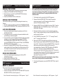
1
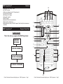
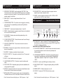
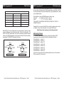
DMX Programmer™
Table of Contents
FLOW CHART................................................................................................1
CONTROLS & FUNCTIONS.......................................................................2
REAR CONTROLS.........................................................................................4
DMX-512 SET UP & ADDRESSING..............................................................5
DMX
PROGRAMMER
PROGRAMMING SCENES..........................................................................9
PROGRAMMING SCENES REVIEW:.......................................................10
SCENE COPY:.......................................................................................11
SCENE EDITING:...................................................................................11
RESET MEMORY....................................................................................11
DELETE SCENE ....................................................................................11
RECORDING PROGRAMS...........................................................................12
EDITING PROGRAMS...................................................................................13
INSERT A STEP:....................................................................................13
DELETE A STEP:....................................................................................14
DELETE A COMPLETE PROGRAM:......................................................14
PLAYBACK SCENES & PROGRAMS...........................................................15
MANUAL RUN SCENES:.......................................................................15
MANUAL RUN PROGRAMS..................................................................15
AUTO RUN PROGRAMS.......................................................................15
MUSIC RUN PROGRAMS.....................................................................15
RESET ALL MEMORY ..................................................................................15
ASSIGNABLE JOYSTICK..............................................................................16
BLACKOUT DELAY TIME.............................................................................17
FADER LEVEL DISPLAY (PERCENT OR VALUE)........................................17
READ AND WRITE A CF CARD..................................................................18
DMX-512
SOFTWARE DOWNLOADING......................................................................19
DATA UPLOAD/DOWNLOAD.......................................................................20
TROUBLE SHOOTING.................................................................................23
Elation Professional®
©
Rev. 7/04
4295 Charter Street
Los Angeles Ca. 90058
www.elationlighting.com
DIPSWITCH DMX ADDRESS CHARTS.......................................................24
CUSTOMER SUPPORT................................................................................25
WARRANTY...............................................................................................26
SPECIFICATIONS.........................................................................................29
DMX Programmer™
•
•
•
•
•
•
•
•
•
•
Features
Reversible DMX Polarity Output
64 DMX Channels
8 Scanners buttons (up to 8 Channels each)
4 Programs of 99 steps
96 Scenes in 24 Pages
Assignable Joystick
Audio Program
Speed and Fade time adjustments
Blackout Delay Adjustment
Backup Memory using a 32 MB Compact Flash Card (Not Included and
Optional)
DMX Programmer™
10
9
11
8
Program Flow Chart
7
FLOW CHART
This is the order you program the DMX Programmer.
ADDRESS
FIXTURES
12
13
6
5
4
14
15
16
17
3
2
RECORD SCENES
1
RECORD PROGRAMS
18
PLAYBACK PROGRAMS
19
Elation Professional® www.elationlighting.com - DMX Programmer
Page 1
Elation Professional® www.elationlighting.com - DMX Programmer
Page 2
DMX Programmer™
Controls and Functions
1. FIXTURE BUTTONS - Used to Select any or all of 8 fixtures.
DMX Programmer™
Controls and Functions
the fixture. When the LED is off, the fader will control Speed Time.
2. SPEED/FADE TIME FADER- Used to adjust the FADE TIME. Fade
Time is the amount of time it takes the DMX Programmer to completely
change from one scene to another. Used also to adjust the rate of the
program speed in Auto Mode.
3. BANK SELECT - Used to change between fixtures 1-4 and
fixtures 5-8.
18. SCENE BUTTONS - Used to store Scenes in program mode or
playback your scenes in playback mode
19. FADERS - Used to adjust the intensity from 0% to 100% or DMX
output level from 0 to 255 of each channel.
DMX Programmer™
Rear Controls and Functions
4. FOG MACHINE BUTTON - This button can be a trigger for controlling
a fog machine. For compatiable fog machines see Fog Machine
Connector (22).
5. PAGE SELECT - Used to select between faders 1-4 and 5-8.
6. GROUP - When this button is pressed, several fixtures can be selected
at a time. See Fixture Buttons (1).
7. LED WINDOW - Displays values and settings depending on the
chosen function.
8. UP AND DOWN BUTTONS - These buttons are used to scroll through
menus, pages, and steps.
9. USB LIGHT CONNECTION - This connector is used to connect a
gooseneck light.
10. PROGRAM - There are four program buttons, these button are used to
store or load programs.
11. BLACKOUT - Disables or enables all channel outputs.
12. PAN/TILT JOYSTICK - This joystick controls the Pan or Tilt movement
of fixtures.
13. DELETE - Used to delete scenes and programs.
14. AUDIO/PREVIEW BUTTON - This button is used to activate audio
mode.
20
21
22
23
24
25
26
20. CF CARD SLOT - Insert or unload a CF Card (Compact Flash Card)
which allows you to back up the memory using a 32 MB Compact Flash
Card. (Not Included and Optional)
Notice: Use only a 32 MB Compact Flash Card.
21. 9-Pin RS-232 CONNECTOR - The RS-232 port can be usde to connect
to a personal computer in order to do memory backups and
software updates.
22. FOG MACHINE CONNECTOR - Connects to a fog machine using a
5-pin cable. Compatiable fog machines include the Master Blaster
1000, Stallion, Vaporizer™, Vapor Flow™, Fog Storm 1200™ and
1700™.
23. DMX OUT - Used to send DMX signal to fixtures or Packs.
15. TAP SYNC BUTTON - Repeatedly tapping this button establishes the
running speed of a program.
24. DMX POLARITY SELECT - Changes the polarity setting of the DMX
output.
16. RECORD - Pressing this button for 3 seconds, activates Record mode.
Use this button to record scenes and programs.
25. POWER SWITCH - Switches the power on or off.
17. SPEED+FADE BUTTON - Used to transfer control of the Speed/Fade
Time Slider. When the LED is lit the fader will control the Fade Time of
Elation Professional® www.elationlighting.com - DMX Programmer
Page 3
26. DC INPUT - Accepts a DC 9V, 500 mA minimum, power
supply.
Elation Professional® www.elationlighting.com - DMX Programmer
Page 4
POWER
DMX Programmer™
DMX Set Up
DMX-512: DMX is short for Digital Multiplex. This is a universal protocol used
as a form of communication between intelligent fixtures and controllers. A
DMX controller sends DMX data instructions from the controller to the fixture. DMX data is sent as serial data that travels from fixture to fixture via the
DATA “IN” and DATA “OUT” XLR terminals located on all DMX fixtures (most
controllers only have a DATA “OUT” terminal).
REMOTE
CONTROL
INPUT
INPUT
OUTPUT
COMMON
REMOTE
CONTROL
1 Ground
Set DMX address 7:
Dip-switches # 1 = 1
2=2
3=4
=7
Data Cable (DMX Cable) Requirements (For DMX and Master/Slave Operation): Your DMX Programmer™ and your fixture require a standard 3-pin
XLR connector for data input and data output (Figure 1). If you are making
your own cables, be sure to use standard two conductor shielded cable (This
cable may be purprogramd at almost all pro sound and lighting stores). Your
cables should be made with a male and female XLR connector on either end
of the cable. Also remember that DMX cable must be daisy chained and can
not be split.
Elation Professional® www.elationlighting.com - DMX Programmer
Page 5
2
1
DMX512 IN
3-PIN XLR
3
2
INPUT
OUTPUT
SOUND
XLR Female Socket
2 Cold
2 Cold
1 Ground
REMOTE
CONTROL
INPUT
INPUT
Termination reduce
avoids signal tran
and interference. It
to connect a DMX te
120 Ohm 1/4 W) be
and PIN 3 (DMX +
OUTPUT
XLR Pin Configuration
Pin 1 = Ground
Pin 2 = Data Compliment (negative)
3 Hot
Figure 3
3 Hot
Pin 3 = Data True (positive)
POWER
POWER
Special Note: Line Termination. When longer runs of cable are used, you
may need to use a terminator on the last unit to avoid erratic behavior. A terminator is a 90-120 ohm 1/4 watt resistor which is connected between pins
2 and 3 of a male XLR connector (DATA + and DATA -). This unit is inserted
in the female XLR socket of the last unit in your daisy chain to terminate the
line. Using a cable terminator (ADJ part number Z-DMX/T) will decrease the
possibilities of erratic behavior.
1
Set DMX address 1:
Dip-switches # 1 = 1
1
3
DMX -
2
XLRINPUT
Male Socket
POWER
2
3
Figure 2
DMX Linking: DMX is a language allowing all makes and models of different
manufactures to be linked together and operate from a single controller, as
long as all fixtures and the controller are DMX compliant. To ensure proper
DMX data transmission, when using several DMX fixtures try to use the shortest cable path possible. The order in which fixtures are connected in a DMX
line does not influence the DMX addressing. For example; a fixture assigned a
DMX address of 1 may be placed anywhere in a DMX line, at the beginning, at
the end, or anywhere in the middle. When a fixture is assigned a DMX address
DMX512
of 1, the DMX controller knows to send DATA assigned
to address 1 to that
DMX+,DMX-,COMMON
unit, no matter where it is located in the DMX chain.
3
DMX +
1
DMX512 OUT
3-PIN XLR
SOUND
Assigning DMX Address: Each dipswitch has a preset value. A specific DMX
address is set by combining the dipswitches that sum your desired value.
For example: To achieve a DMX address of 7, combine dipswitches 1, 2, and
3. Since dipswitch 1 has a value of 1, dipswitch 2 has a value of 2, COMMON
and dipswitch 3 has a value of 4, the combination of theDMX512
threeOUT
create a DMX
value
DMX
+
3-PIN XLR
DMX of 7. (See example below).
DMX Set Up
Notice: Be sure toDMX512
follow figures two and three when making your own
DMX+,DMX-,COMMON
cables. Do not use the ground lug on the XLR connector. Do not connect
the cable’s shield conductor to the ground lug or allow the shield conductor
to come in contact with the XLR’s outer casing. Grounding the shield could
cause a short circuit and erratic behavior.
Power Supply: Before plugging your unit in, be sure the source voltage in
your area matches the required voltage for your Elation® DMX Programmer.™
The Elation® DMX Programmer™ is 120v only. Because line voltage may vary
from venue to venue, you should be sure your controller voltage matches the
wall outlet voltage before attempting to operate you fixture.
SOUND
POWER
DMX Programmer™
1
3
2
DMX512 IN
3-PIN XLR
1
3
2
Termination reduces signal errors and
avoids signal transmission problems
and interference. It is always advisable
to connect a DMX terminal, (Resistance
120 Ohm 1/4 W) between PIN 2 (DMX-)
and PIN 3 (DMX +) of the last fixture.
Figure 4
5-Pin XLR DMX Connectors. Some manufactures use 5-pin XLR connectors
for DATA transmission in place of 3-pin. 5-pin XLR fixtures may be implemented in a 3-pin XLR DMX line. When inserting standard 5-pin XLR connectors
in to a 3-pin line a cable adaptor must be used, these adaptors are readily
available at most electric stores. The chart below details a proper cable conversion.
Elation Professional® www.elationlighting.com - DMX Programmer
Page 6
DMX Programmer™
DMX Set Up
3-Pin XLR to 5-Pin XLR Conversion
Conductor
3-Pin XLR Female (Out)
5-Pin XLR Male (In)
Ground/Shield
Pin 1
Pin 1
Data Compliment (- signal)
Pin 2
Pin 2
Data True (+ signal)
Pin 3
Pin 3
Not Used
Pin 4 - Do Not Use
Not Used
Pin 5 - Do Not Use
While DMX 512 is the standard used to control lighting, at this time, there
are some differences you should know about. One is pin configuration. The
DATA + And DATA- are reversed. This can be corrected by using the reversal
switch on the DMX Programmer. If you have some fixtures from each polarity
use adapter Z-DMXADAPT between the fixtures.
TYPE 1
TYPE 2
XLR MALE SOCKET
Data+ 2
3 Data -
XLR MALE SOCKET
Data - 2
3 Data +
1 Ground
DATA IN
1 Ground
DATA IN
Elation Professional® www.elationlighting.com - DMX Programmer
Page 7
DMX Programmer™
DMX Addressing
DMX 512 is a type of protocol that sends out up to 512 multiplex channels
at once down a common cable. Each channels has a value from 0 to 255.
You set the address for each receiver(fixture) by using Dipswitches or some
type of digital readout
Each Dipswitch has an ADDRESS based on binary code.
Dipswitch
#1 #2 #3 #4 #5 #6 #7 #8 #9
Value
1 2 4 8 16 32 64 128 256
YOU SELECT THE ADDRESS WANTED BY ADDING THE TOTAL OF
DIPSWITCHES ON.
Dipswitch #10 is not used with DMX but normally to select some Function
ie: Master / Slave, Sound Activation or to receive DMX Control.
Most fixtures start receiving on the address selected
Addressing Fixtures
In order to have individual control of each fixture with the DMX
Programmer Fixture addresses should be addressed as follows.
Fixture Button # 1 starts at 1
Fixture Button # 2 starts at 9
Fixture Button # 3 starts at 17
Fixture Button # 4 starts at 25
Fixture Button # 5 starts at 33
Fixture Button # 6 starts at 41
Fixture Button # 7 starts at 49
Fixture Button # 8 starts at 57
If you are not sure how to set the starting address of your Fixture refer to
Chart on page 23 of this manual.
Elation Professional® www.elationlighting.com - DMX Programmer
Page 8
DMX Programmer™
Programming Scenes
1. PRESS AND HOLD the RECORD BUTTON for three (3) seconds to
activate record mode. A red LED above the button will be lit
and the LCD WINDOW will indicate your in record mode by displaying “1: REC”. Press the RECORD BUTTON again, the LCD Display
will show “REC.”
2. Select a fixture(s) to program, by pressing any or all FIXTURE BUTTONS
1 - 8. Press the BANK BUTTON to switch to fixtures 5 - 8.
3. Adjust the faders to the desired settings of the fixture or fixtures your
programming (i.e. Color, Gobo, Pan, Tilt, Speed, etc.), by adjusting
the fader values. Use the PAGE A B BUTTON if your Fixture has more
than eight channels. When selecting from Page A to B you have to
move Sliders to activate channels
4. Once you’ve reached your desired setting and or position for the fixture,
you can press the FIXTURE BUTTON for the fixture you were
adjusting this stops adjustment of that Fixture(s). You then press another
FIXTURE BUTTON to select another Fixture to adjust.You can adjust
more than one fixture at a time by the holding the GROUP BUTTON and
selecting more than one Fixture Button at a time
5. Repeat steps 2 and 3 until all the lights are where you want.
6. When entire scene is set to your liking, Simultaneously, press a SCENE
BUTTON 1-4 of your choice, and the RECORD BUTTON. All LEDs will
blink and one scene will be recorded.
You can copy the settings from one scanner button to another in case you
want to add more lights to your show. just press and hold the scanner button
you want to copy then press the Scanner button you want to copy to
7. Now use the UP and DOWN BUTTONS to change the pages of scenes.
There are 24 pages you can store up to 4 scenes per page for a total of
96 scenes.
8. To exit programming mode press and hold the RECORD BUTTON
for 3 seconds.
Elation Professional® www.elationlighting.com - DMX Programmer
Page 9
DMX Programmer™
Programming Scenes Review
To review, this is how you would create a simple 4 step box pattern
1. PRESS AND HOLD the RECORD BUTTON for three (3) seconds to
activate record mode. A red LED above the button will be lit
and the LCD WINDOW will indicate your in record mode by displaying “1: REC”. Press the RECORD BUTTON again, the LCD Display
will show “REC.”
2. Select a fixture(s) to program using the FIXTURE BUTTONS 1 TO 8
NOTE: WHEN YOU ARE BEGINNING IT MAY BE EASIER TO USE FOUR
CUPS OR OTHER OBJECTS PLACED ON THE FLOOR AS A GUIDE.
3. Adjust the faders to the desired Color, Gobo, then using the Pan, Tilt,
adjust the mirrors to go to the bottom corner of the dance floor.
4. Press the RECORD BUTTON and SCENE 1 BUTTON simultaneously.
ALL LEDS BLINK 3 TIMES.
5. Adjust the Pan faders to adjust the mirrors to go across to the other
bottom corner of the dance floor.
6. Press the RECORD BUTTON and SCENE 2 BUTTON simultaneously.
ALL LEDS BLINK 3 TIMES.
7. Adjust the tilt fader to adjust the mirrors to go up to the top corner
of the dance floor.
8. Press the RECORD BUTTON and SCENE 3 BUTTON simultaneously.
ALL LEDS BLINK 3 TIMES
9. Adjust the Pan fader to adjust the mirrors to go across to the other
top corner of the dance floor. By pressing Scene buttons 1 to 4 in
order you should have a box pattern. If you have a problem refer to
Trouble shooting, page 16.
You can now use these scenes to make scenes 5-8. Same box
patterns with different colors and gobos. To do this, you must first
switch to a new page. Do this by pressing the UP BUTTON. The LED
Window will read “PA:02”.
10. Press the UP BUTTON, PA:02 will be displayed in the LED Window.
11. Repeat above steps 3-9.
THIS WILL GIVE YOU 2 PAGES WITH 4 SCENES EACH, AND 2 DIFFERENT COLORED BOX PATTERNS.
ONCE YOU HAVE RECORDED ALL THE SCENES YOU CAN NOW GO
TO PROGRAMMING PROGRAMS PAGE 14.
Elation Professional® www.elationlighting.com - DMX Programmer
Page 10
DMX Programmer™
Editing Scenes
SCENE COPY:
This function allows you to copy the settings of one scene to another.
1. PRESS AND HOLD the RECORD BUTTON for three (3) seconds to
activate record mode. A red LED above the button will be lit
and the LCD WINDOW will indicate your in record mode by displaying “1: REC”. Press the RECORD BUTTON again, the LCD Display
will show “REC.”.’
2. Use the UP and DOWN BUTTONS to locate the page that contains the
scene you wish to copy.
3. Press the SCENE BUTTON, that contains the scene you want to copy.
4. Use the UP and DOWN BUTTONS to select the page you want to
copy the scene to.
5. Simultaneously, press the RECORD BUTTON and the SCENE BUTTON
you wish to copy to.
DMX Programmer™
Recording Programs
RECORD A PROGRAM USING PRE-PROGRAMMED
SCENES:
SCENE EDITING:
1. PRESS AND HOLD the RECORD BUTTON for three (3) seconds to
activate record mode. A red LED above the button will be lit
and the LCD WINDOW will indicate you are in record mode by displaying “1: REC”.
2. Press the RECORD BUTTON again, the LCD Display will show “REC.”
3. Select one of the four PROGRAM BUTTONS that you wish to record
into. Once you have selected a program, the green LED above the
selected button will continually flash and the LCD will indicated you are
in record program mode by displaying “St:00”. This means you are
at step zero for the selected program.
4. Press one of four scene button to activate the scene page menu. The
LCD will display the current active scene page by displaying; “PA:0124”. “PA” is an abbreviation for Page and “01-24” is the page number.
5. Select a desird SCENE from any page that has been previously recorded. Scroll through the SCENE pages by using up and down arrow buttons. A scene which has been programmed will have a solid green LED
lit over the button. Once a scene is selected, the green LED above the
selected button will flash continually indicating that it’s the last selected scene.
NOTE: If you have already recorded a program in the selected program
button, pressing the arrow keys will manually cycle through each previosly
recorded step. If you have selected this program button accidentally and
do not wish to record over the current program, press and hold RECORD
for (3) seconds to exit).
DELETE A SCENE:
6. Set the speed and fade time by using the “SPEED FADER” and the
“SPEED+FADE” button. The yellow LED above the button should be
OFF for Speed setting and ON for Fade setting. The range is between
five tenths of a second (0.05) and ten (10) minutes for each.
7. Press the RECORD BUTTON. All LED’s will flash. Each time the
RECORD BUTTON is pressed, all LED’s will flash and the step will
advance once. EX. - “St:01, St:02, St:03, St:04, etc....
8. Repeat steps 5-7 if you want to continue to store steps. Up to 99
steps can be put into one program.
9. To exit programming press the RECORD BUTTON for three (3) seconds to de-activate program mode.
This function allows you to make changes in a scene after it has been
programmed.
1. PRESS AND HOLD the RECORD BUTTON for three (3) seconds to
activate record mode. A red LED above the button will be lit
and the LCD WINDOW will indicate your in record mode by displaying “1: REC”. Press the RECORD BUTTON again, the LCD Display
will show “REC.”
2. Use the UP AND DOWN BUTTONS to select the page that stores
the scene you wish to edit.
3. Select the scene you want to edit by pressing its SCENE BUTTON.
4. Use the FADERS to make your desired adjustments.
5. Once you’ve made your changes, simultaneously press the RECORD
BUTTON and the SCENE BUTTON that corresponds to the scene your
editing. This will store the edited scene back into memory.
Be sure to selected the same scene you selected in step 4, otherwise you
may accidentally record over an existing scene.
This will delete a single SCENE. Make sure you are in RECORD mode.
1. While pressing DELETE, press and release the SCENE BUTTON 1-4
you want to delete.
Elation Professional® www.elationlighting.com - DMX Programmer
Page 11
Elation Professional® www.elationlighting.com - DMX Programmer
Page 12
DMX Programmer™
Recording Programs
RECORD A PROGRAM ON THE FLY:
1. PRESS AND HOLD the RECORD BUTTON for three (3) seconds to
activate record mode. A red LED above the button will be lit
and the LCD WINDOW will indicate you are in record mode by displaying “1: REC”.
2. Press the RECORD BUTTON again, the LCD Display will show “REC.”
3. Select one of the four PROGRAM BUTTONS that you wish to record
into. Once you have selected a program, the green LED above the
selected button will continually flash and the LCD will indicated you are
in record program mode by displaying “St:00”. This means you are
at step zero for the selected program.
4. Select the fixture or fixtures that you want included into your first program step by pressing the FIXTURE BUTTONS 1-4 on bank one and 58 on bank two. Next, using the faders and joysticks set the look you
want for your first step.
NOTE: When using the faders, channels 1-4 can be adjusted when the
page LED is OFF and channels 5-8 when the PAGE LED is ON.
5. Set the speed and fade time by using the “SPEED FADER” and the
“SPEED+FADE” button. The yellow LED above the button should be
OFF for Speed setting and ON for Fade setting. The range is between
five tenths of a second (0.05) and ten (10) minutes for each.
6. Press the RECORD BUTTON. All LED’s will flash. Each time the
RECORD BUTTON is pressed, all LED’s will flash and the step will
advance once. EX. - “St:01, St:02, St:03, St:04, etc....
7. Repeat steps 5-7 if you want to continue to store steps. Up to 99 steps
can be put into one program.
8. To exit programming press the RECORD BUTTON for three (3) seconds to de-activate program mode.
DMX Programmer™
Editing Programs
INSERT A STEP:
1. PRESS AND HOLD the RECORD BUTTON for three (3) seconds to
activate record mode. A red LED above the button will be lit
and the LCD WINDOW will indicate your in record mode by displaying “1: REC”. Press the RECORD BUTTON again, the LCD Display
will show “REC.”
2. Select the PROGRAM 1 TO 4 you wish to add a step to.
Elation Professional® www.elationlighting.com - DMX Programmer
Page 13
DMX Programmer™
Editing Programs
3. Use the UP and DOWN BUTTONS, to manually scroll to the STEP you
wish to insert a step after.
4. Press the Scene Button you want to insert
5. Press RECORD BUTTON to insert new step. All LED’s will blink.
6. To exit programming press the RECORD BUTTON for three (3) seconds to de-activate program mode.
DMX Programmer™
Deleting Steps and Programs
DELETE A STEP:
1. PRESS AND HOLD the RECORD BUTTON for three (3) seconds to
activate record mode. A red LED above the button will be lit
and the LCD WINDOW will indicate your in record mode by displaying “1: REC”. Press the RECORD BUTTON again, the LCD Display
will show “REC.”
2. Select the PROGRAM 1 TO 4 that contains the step you would like to
delete.
3. Use the UP and DOWN BUTTONS, to manually scroll to the step you
wish to delete.
4. When you have reached the step you wish to delete, press and
release the DELETE BUTTON. All LED’s will blink.
5. To exit programming press the RECORD BUTTON for three (3) seconds to de-activate program mode.
DELETE A COMPLETE PROGRAMS:
1. PRESS AND HOLD the RECORD BUTTON for three (3) seconds to
activate record mode. A red LED above the button will be lit
and the LCD WINDOW will indicate your in record mode by displaying “1: REC”. Press the RECORD BUTTON again, the LCD Display
will show “REC.”
2. Press and hold down the PROGRAM BUTTON that you want to delete.
3. While holding down the PROGRAM BUTTON press and release the
DELETE BUTTON. All LED’s will blink, and “del” will show in the LED
Window.
4. Release the PROGRAM BUTTON. The program should be deleted.
5. To exit programming press the RECORD BUTTON for three (3) seconds to de-activate program mode.
Elation Professional® www.elationlighting.com - DMX Programmer
Page 14
DMX Programmer™
Playback Scenes and Programs
MANUAL RUN SCENES:
1. When power is first turned on, the unit is in manual scene mode.
2. Make sure AUTO & MUSIC LED’S BUTTONS are off .
3. Select the page, using the UP and DOWN BUTTONS, that store
the scenes you wish to run.
4. Press the a SCENE BUTTON to run the scene.
MANUAL RUN PROGRAMS:
This function will allow you to manually step through all scenes in any
Program.
1. Execute a program by selecting one of the four PROGRAM BUTTONS.
2. Press the AUDIO/PREVIEW BUTTON, and tap the TAP/SYNC BUTTON.
AUTO RUN PROGRAMS:
1. Select your desired program program by pressing any of the four
PROGRAM BUTTONS.
2. The program will now run according to the speed and fade time that
you set when you made the program.
3. If you would like to control the speed and fade time while your program
is running, you need to press and hold your desired PROGRAM
BUTTON and press the SPEED+FADE BUTTON. You can now let
go of the PROGRAM BUTTON, the green LED next to the PROGRAM
BUTTON should be flashing quickly.
4. Now when you press the SPEED+TIME BUTTON you will be able to
switch between Fade Time and Speed Time. When the button LED is
lit, the fader will control the Fade Time. When the LED is not lit, the
fader will control the Speed Time.
MUSIC RUN PROGRAMS:
1. Select your desired program by pressing one of the four PRO
GRAMMED BUTTONS.
2. Press the AUDIO/PREVIEW BUTTON.
3. Program will now run in sound active mode.
DMX Programmer™
Reset All Memory
DMX Programmer™
Assignable Joystick
NOTE: The joystick will be pre-assigned to work with most American
DJ and Elation light fixtures. When using the controller with light fixtures other then American DJ and Elation, the joystick may have to be
assigned to those light fixtures. To assign the joystick follow the instructions below.
1. The fixture(s) must be connected to the DMX Programmer.
2. Press and hold the RECORD BUTTON for three (3) seconds to
activate record mode. A red LED above the button will be lit
and the LCD Window will display “1: REC”.
3. Press the UP BUTTON, the LED WINDOW will show “2:SEt”. Press the
RECORD BUTTON, the LED WINDOW will show “1:ASS”. Press the
RECORD BUTTON, again.
4. Now select the fixture or fixtures you want to assign the joystick to
control. To select multiple fixtures you must hold the GROUP BUTTON
and then select the fixtures.
5. The LED WINDOW will now show “C1:L1”. “C1” meaning Channel 1,
and “L1” meaning Output Channel 1.
6. Press the UP BUTTON to toggle through the Channel number and
Output Channel number. Press the UP BUTTON until the LED WINDOW
shows “PA:C-” (Pan Control). Press the DOWN BUTTON, to change the
output channel to whichever channel is the Pan channel on
your selected fixture. Press the UP BUTTON until the LED WINDOW
shows “tI:C-” (Tilt Control). Press the DOWN BUTTON, to
change the output channel to whichever channel is the Tilt channel on
your selected fixture. Press the RECORD BUTTON, If the channel patch
is successful, all LED’s will blink, and the LED WINDOW will
show “good”, then return to “C1:L1”.
NOTE: You must set both pan and tilt channels before saving. Saving
one at a time, will only save the last selected setting.
7. To exit Joystick Assignment, press the RECORD BUTTON for three (3)
seconds.
RESET ALL MEMORY:
This function will erase all scenes and program programs.
The unit must be off, to perform this function.
1. Press and hold down the SCENE 2 BUTTON, BANK BUTTON, and the
BLACKOUT BUTTON, and turn the power on.
Elation Professional® www.elationlighting.com - DMX Programmer
Page 15
Elation Professional® www.elationlighting.com - DMX Programmer
Page 16
DMX Programmer™
Settings
SETTTING BLACKOUT DELAY TIME
1. Press and hold the RECORD BUTTON for three (3) seconds to
activate record mode. A red LED above the button will be lit
and the LCD Window will display “1: REC”.
2. Press the UP BUTTON, the LED WINDOW will show “2:SEt”. Press the
RECORD BUTTON, the LED WINDOW will show “1:ASS”.
3. Press the UP BUTTON, the LED WINDOW will now show “2:blt”.
4. Press the RECORD BUTTON, the LED WINDOW will now show “bt:00”.
5. Now using the UP and DOWN BUTTONS you can adjust the Blackout
Delay time from 1 - 10 seconds.
6. To exit Blackout Delay setting, press and hold the RECORD BUTTON
for three (3) seconds.
NOTE: Pressing the BLACKOUT BUTTON for one second can bypass
Blackout delay.
PERCENT OR VALUE DISPLAY
You can choose whether the display shows the fader level as a Percentage
or Value. 100 means the display is showing percentage level. 255 means
the display is showing the value level.
1. Press and hold the RECORD BUTTON for three (3) seconds to
activate record mode. A red LED above the button will be lit
and the LCD Window will display “1: REC”.
2. Press the UP BUTTON, the LED WINDOW will show “2:SEt”. Press the
RECORD BUTTON, the LED WINDOW will show “1:ASS”.
3. Press the DOWN BUTTON, the LED WINDOW will now show “3:dis”.
4. Press the RECORD BUTTON, the LED WINDOW will now show “255”.
5. Now using the UP or DOWN BUTTON you can choose between
Percent or Value display.
6. To exit Display setting, press and hold the RECORD BUTTON
for three (3) seconds.
Elation Professional® www.elationlighting.com - DMX Programmer
Page 17
DMX Programmer™
Write A CF Card
There are 7 data folders in the CF Card Menu. All “ALL”, Scenes “SCEN,
Program 1 “Pro1”, Program 2 “Pro2”, Program 3 “Pro3, Program 4 “Pro4”,
and Set “SEt”.
1. Press and hold the RECORD BUTTON for three (3) seconds to
activate record mode. A red LED above the button will be lit
and the LCD Window will display “1: REC”.
2. Press the UP BUTTON, until the LED WINDOW shows “3: CF”. Press
the RECORD BUTTON, the LED WINDOW will show “1: St”.
3. Press the RECORD BUTTON, the LED WINDOW will now show “ALL”.
Press the UP BUTTON will let you scroll through all the data folders.
Select the data folder you want to write to and press the RECORD
BUTTON. Select a desired location between 01 - 99.
4. Press the RECORD BUTTON, the LED WINDOW will show “Stor”, while
the writing the CF Card. “Good” will appear in the LCD WINDOW,
when the writing proces is complete and successfull, and then will
exit Record mode automatically. If the process is not successful the
LED WINDOW will show “Err”, and then will exit Record mode automatically. Note: If the DMX Programmer continues to show “Err”,
make sure that your CF Card is formatted.
DMX Programmer™
Read A CF Card
There are 7 data folders in the CF Card Menu. All “ALL”, Scenes “SCEN,
Program 1 “Pro1”, Program 2 “Pro2”, Program 3 “Pro3, Program 4 “Pro4”,
and Set “SEt”.
1. Press and hold the RECORD BUTTON for three (3) seconds to
activate record mode. A red LED above the button will be lit
and the LCD Window will display “1: REC”.
2. Press the UP BUTTON, until the LED WINDOW shows “3: CF”. Press
the RECORD BUTTON, the LED WINDOW will show “2: rd”.
3. Press the RECORD BUTTON, the LED WINDOW will now show “ALL”.
Press the UP BUTTON will let you scroll through all the data folders.
Select the data folder you want to read and press the RECORD
BUTTON. Select the desired folder between 01 - 99.
4. Press the RECORD BUTTON, the LED WINDOW will show “rEAD”,
while reading the CF Card. “Good” will appear in the LCD WINDOW,
when the reading proces is complete and successfull, and then will
exit Record mode automatically. If the process is not successful the
LED WINDOW will show “Err”, and then will exit Record mode automatically.
NOTE: The successful operation will lose all the previous data. To protect this data, write it to a CF Card or computer database.
Elation Professional® www.elationlighting.com - DMX Programmer
Page 18
DMX Programmer™
Dowloading and Uploading
Dowloading and Uploading
hold FIXTURE BUTTONS 1, 2, 3, and 4, and switch the unit “On”.
DOWNLOAD SOFTWARE BY RS-232
To connect to a PC, you will need a serial lap link cable. NOTE: A standard RS-232 cable will not work. This cable is available at any computer
store. You will also need a PC that is running Windows Version 95/98/2000
or higher. Windows comes with an accessory called Hyper Terminal that
can communicate with SD-808 via one of the “COM” ports on your PC.
Determine which of your “COM” ports is available. COM 1 is generally used
for the mouse, so it is advisable to connect to COM 2 on your PC.
You must first configure Hyper Terminal to work with the DMX Programmer.
1. Start the Hyper Terminal program by clicking on “Start” in Windows,
then “Programs” then “Accessories” then “Communications” then
“Hyper Terminal”.
2. Once the Hyper Terminal Program is getting started, you will be asked
to choose a name and icon. Name it DMX PROGRAMMER then pick
any icon then click OK. Go to the next dialog box “Connect to” and
choose “Direct to COM 2” or whichever port is free. Ignore the telephone number and other setting in this box, then click “OK”.
3. In the next dialog box, set the Bits per Second to 57,600, the Data Bits
to 8, Parity to none, Stop Bits to 1, Flow Control to none, and then
click “OK”. You will then access the Hyper Terminal desktop.
Once you access the Hyper Terminal desktop, click the File menu in the
upper left corner of the desktop. Go into “Properties”, then select the “settings” tab. Now that you are in the “settings” menu, click on “ASCII Setup”.
In the next menu, leave all the settings deselected, then click “OK”. Close
and save the Hyper Terminal. You may want to make a shortcut on your
desktop. Now you can click on the DMX PROGRAMMER.ht icon to access
the Hyper Terminal configuration quickly.
4. Click on the “Transfer” menu in the menu bar, then select “Send text
file”.
5. A dialog box will appear, that allows you to select the data file that you
want to send. Be sure that the file is available. Clicking “OK” will allow
the unit SD-808 to download the software from the computer. While
downloading the LED WINDOW will flash “rECE”.
6. If you succeeded in downloading the software, the LED WINDOW will
show “good”, and will automatically exit from Record mode. If the
download fails, the LED WINDOW will show “Err”. If this occurs, find
out where the problem is and make adjustments, and try again.
7. If this unit loses the software because of a download faliure, you can
Elation Professional® www.elationlighting.com - DMX Programmer
DMX Programmer™
Page 19
If for someone reason Hyper Terminal is not installed on your version
of Windows, install it from your Windows CD. Go to the Control Panel,
select Add/Remove Programs, select Windows Setup, and then select
Communication. Follow the instructions to complete the installation.
1. Press and hold the RECORD BUTTON for three (3) seconds to
activate record mode. A red LED above the button will be lit
and the LCD Window will display “1: REC”.
2. Press the UP BUTTON, until the LED WINDOW shows “4:232”. Press
the RECORD BUTTON, the LED WINDOW will show “1: SOF”.
3. Press the RECORD BUTTON, the LED WINDOW will now show
“SOFT”, indicating the DMX Programmer is now receiving the software.
4. If you would like to exit from software download, press and hold the
RECORD BUTTON for three (3) seconds.
DATA UPLOAD
There are seven (7) data folders for Data Upload options, including All
“ALL”, Scenes “SCEN”, Program 1 “Pr01”, Program 2 “Pr02”, Program 3
“Pr03”, Program 4 “Pr04”, and Set “SEt”.
1. Press and hold the RECORD BUTTON for three (3) seconds to
activate record mode. A red LED above the button will be lit
and the LCD Window will display “1: REC”.
2. Press the UP BUTTON, until the LED WINDOW shows “4:232”. Press
the RECORD BUTTON, press the UP BUTTON until the LED WINDOW
shows “2:U.Pr”.
3. Press the RECORD BUTTON to access data upload, the LED WINDOW
will now show “ALL”, one of the seven (7) data folders in the DMX
Programmer.
4. Select the desired data folder you wish to backup on your PC.
5. Connect the DMX Programmer to the PC.
6. Select the version of Hyper Terminal that you created and saved to your
desktop. Click on the top menu bar and select “Capture Text”. A
dialogue box will appear allowing you to select a folder and name for
the data file you will send. Click “Start”, and Hyper Terminal will now
start the process of receiving the data file from your DMX Programmer.
7. Press the RECORD BUTTON, the LED WINDOW will show “SEND”,
which indicates it is sending the file.
8, If you succeeded in uploading the data file, the LED WINDOW will
Elation Professional® www.elationlighting.com - DMX Programmer
Page 20
DMX Programmer™
Downloading and Uploading
show “good”, and will automatically exit from Record mode. If the
upload fails, the LED WINDOW will show “Err”. If this occurs, check all
connections and configurations, and try again.
DMX Programmer™
4.
DATA DOWNLOAD
There are seven (7) data folders for Data Download options, including All
“ALL”, Scenes “SCEN”, Program 1 “Pr01”, Program 2 “Pr02”, Program 3
“Pr03”, Program 4 “Pr04”, and Set “SEt”.
1. Connect the DMX Programmer to the PC.
2. Press and hold the RECORD BUTTON for three (3) seconds to
activate record mode. A red LED above the button will be lit
and the LCD Window will display “1: REC”.
3. Press the UP BUTTON, until the LED WINDOW shows “4:232”. Press
the RECORD BUTTON, press the UP BUTTON until the LED WINDOW
shows “3:d.Pr”.
4. Press the RECORD BUTTON to access data download, the LED
WINDOW will now show “ALL”, one of the seven (7) data folders in the
DMX Programmer.
5. Select the desired data file you wish to download from your PC.
6. Connect the DMX Programmer to the PC.
7. Press the RECORD BUTTON, the LED WINDOW will show “rECE” and
the RECORD LED will blink, which indicates it is receiving the file. You
can press the RECORD BUTTON at any time to quit this process.
8. On your PC, select the version of Hyper Terminal that you created and s
aved to your desktop.
9. Click on the “Transfer” menu in the menu bar, then select “Send text
file”. Find the drive and folder where the file is located, select the file
and click on “OPEN”.
10. If you succeeded in downloading the data file, the LED WINDOW will
show “good”, and will automatically exit from Record mode. If the
download fails, the LED WINDOW will show “Err”. If this occurs, check
all connections and configurations, and try again.
5.
6.
7.
8.
9.
10.
11.
Downloading and Uploading
the RECORD BUTTON, press the UP BUTTON until the LED WINDOW
shows “3:d.Pr”.
Press the RECORD BUTTON to access data download, the LED
WINDOW will now show “ALL”, one of the seven (7) data folders in the
DMX Programmer.
Select the desired data file you wish to download from your DMX
Programmer.
On the DMX Programmer that you want to Upload data.
Press and hold the RECORD BUTTON for three (3) seconds to
activate record mode. A red LED above the button will be lit
and the LCD Window will display “1: REC”.
Press the UP BUTTON, until the LED WINDOW shows “4:232”. Press
the RECORD BUTTON, press the UP BUTTON until the LED WINDOW
shows “2:U.Pr”.
Press the RECORD BUTTON to access data upload, the LED WINDOW
will now show “ALL”, one of the seven (7) data folders in the DMX
Programmer.
Select the desired data folder you wish to store the download.
Press the RECORD BUTTON on the unit you are downloading from. The
LED WINDOW will show “SEND” and the LED WINDOW of uploading
unit will show “rECE”.
If you succeeded in swapping data, the LED WINDOWs of both units
will show “good”, and will automatically exit from Record mode. If the
swap fails, the LED WINDOWs of both units will show “Err”. If this
occurs, check all connections and configurations, and try again.
DATA SWAP BETWEEN DMX PROGRAMMERS
1. Use a RS-232 cable to connect two DMX Programmers.
2. On the DMX Programmer that you want to download data from.
Press and hold the RECORD BUTTON for three (3) seconds to activate record mode. A red LED above the button will be lit and the
LCD Window will display “1: REC”.
3. Press the UP BUTTON, until the LED WINDOW shows “4:232”. Press
Elation Professional® www.elationlighting.com - DMX Programmer
Page 21
Elation Professional® www.elationlighting.com - DMX Programmer
Page 22
DMX Programmer™
Troubleshooting
Mirrors don’t respond when I move faders
Make sure that the fixture is selected. Make sure address
is correct. Make sure speed is adjusted, if available, for faster
movement. Not all Fixtures have a speed adjustment.
If total of XLR cable is more than 90 feet make sure it is
terminated properly.
Colors don’t respond when I move faders
Make sure that the fixture is selected. Make sure address is
correct. See Chart pages 21 and 22.
If total of XLR cable is more than 90 feet make sure it is
terminated properly.
Scenes don’t playback after I record them
Make sure to press RECORD BUTTON and SCENE BUTTON
simultaneously. LED’s should blink after pressing each
SCENE BUTTON.
Make sure you are in the correct Page that has scenes
recorded.
Programs don’t playback after I record them
Make sure to press RECORD BUTTON, after pressing
SCENE BUTTON. LED’s should blink after pressing RECORD
BUTTON.
Make sure you are in the correct Program that has steps
recorded
Is Fade Time to long for Speed Selected?
If total of XLR cable is more than 90 feet make sure it is
terminated properly.
DMX Programmer™
WHEN STARTING ADDRESS IS THE ONE SELECTED
Fixture 1 Address 1
ON
Page 23
1 2 3 4 5 6 7 8 9 10
Fixture 2 Address 9
ON
1 2 3 4 5 6 7 8 9 10
Fixture 3 Address 17
ON
1 2 3 4 5 6 7 8 9 10
Fixture 4 Address 25
ON
Elation Professional® www.elationlighting.com - DMX Programmer
Dipswitch DMX Address Chart
1 2 3 4 5 6 7 8 9 10
Fixture 5 Address 33
ON
1 2 3 4 5 6 7 8 9 10
Fixture 6 Address 41
ON
1 2 3 4 5 6 7 8 9 10
Fixture 7 Address 49
ON
1 2 3 4 5 6 7 8 9 10
Fixture 8 Address 57
ON
1 2 3 4 5 6 7 8 9 10
Elation Professional® www.elationlighting.com - DMX Programmer
Page 24
DMX Programmer™
Customer Support
Elation® provides a customer support line, to provide set up help
and to answer any question should you encounter problems during your set up or initial operation. You may also visit us on the web
at www.americandj.com for any comments or suggestions. Service
Hours are Monday through Friday 9:00 A.M. to 5:00 P.M., Pacific
Standard Time.
Voice:
(323) 582-3322
Fax:
(323) 582-3108
E-mail:
[email protected]
Warning! To prevent or reduce the risk of electrical shock or fire, do
not expose this unit to rain or moisture.
Caution! There are no user serviceable parts inside this unit. Do not
attempt any repairs yourself, doing so will void your manufactures
warranty. In the unlikely event your unit may require service please
contact Elation®.
DMX Programmer™
Product Registration
The DMX Programmer™ carries a two year limited warranty. Please
fill out the enclosed warranty card to validate your purprogram. All
returned service items whether under warranty or not, must be freight
pre-paid and accompany a return authorization (R.A.) number. The R.A.
number must be clearly written on the outside of the return package. A
brief description of the problem as well as the R.A. number must also
be written down on a piece of paper included in the shipping carton.
If the unit is under warranty, you must provide a copy of your proof of
purprogram invoice. You may obtain a R.A. number by contacting our
customer support team on our customer support number. All packages returned to the service department not displaying a R.A. number
on the outside of the package will be returned to the shipper.
DMX Programmer™
Warranty
TWO YEAR LIMITED WARRANTY
A. Elation® hereby warrants, to the original purprogramr, Elation® products to be free of
manufacturing defects in material and workmanship for a period of 2 Years (730 days) from
the date of purprogram. This warranty shall be valid only if the product is purprogramd within
the United States of America, including possessions and territories. It is the owner’s responsibility to establish the date and place of purprogram by acceptable evidence, at the time
service is sought.
B. For warranty service, send the product only to the Elation® factory. All shipping charges
must be pre-paid. If the requested repairs or service (including parts replacement) are within
the terms of this warranty, Elation® will pay return shipping charges only to a designated
point within the United States. If the entire instrument is sent, it must be shipped in its original
package. No accessories should be shipped with the product. If any accessories are shipped
with the product, Elation® shall have no liability whatsoever for loss of or damage to any such
accessories, nor for the safe return thereof.
C. This warranty is void if the serial number has been altered or removed; if the product is
modified in any manner which Elation® concludes, after inspection, affects the reliability of
the product; if the product has been repaired or serviced by anyone other than the Elation®
factory unless prior written authorization was issued to purprogramr by Elation®; if the product is damaged because not properly maintained as set forth in the instruction manual.
D. This is not a service contract, and this warranty does not include maintenance, cleaning
or periodic check-up. During the period specified above, Elation® will replace defective parts
at its expense, and will absorb all expenses for warranty service and repair labor by reason
of defects in material or workmanship. The sole responsibility of Elation® under this warranty
shall be limited to the repair of the product, or replacement thereof, including parts, at the
sole discretion of Elation®. All products covered by this warranty were manufactured after
January 1, 1990, and bear identifying marks to that effect.
E. Elation® reserves the right to make changes in design and/or improvements upon its
products without any obligation to include these changes in any products theretofore manufactured.
F. No warranty, whether expressed or implied, is given or made with respect to any accessory supplied with products described above. Except to the extent prohibited by applicable
law, all implied warranties made by Elation® in connection with this product, including warranties of merchantability or fitness, are limited in duration to the warranty period set forth
above. And no warranties, whether expressed or implied, including warranties of merchantability or fitness, shall apply to this product after said period has expired. The consumer’s
and or Dealer’s sole remedy shall be such repair or replacement as is expressly provided
above; and under no circumstances shall Elation® be liable for any loss or damage, direct or
consequential, arising out of the use of, or inability to use, this product.
G. This warranty is the only written warranty applicable to Elation® Products and supersedes
all prior warranties and written descriptions of warranty terms and conditions heretofore
published.
Elation Professional® www.elationlighting.com - DMX Programmer
Page 25
Elation Professional® www.elationlighting.com - DMX Programmer
Page 26
DMX Programmer™
Elation Professional® www.elationlighting.com - DMX Programmer
Notes
Page 27
DMX Programmer™
Elation Professional® www.elationlighting.com - DMX Programmer
Notes
Page 28
DMX Programmer™
Specifications
POWER SUPPLY:
DMX CHANNELS:
INPUT/OUTPUTS:
AUDIO TRIGGER:
DIMENSIONS:
WEIGHT:
WARRANTY:
Specifications
DC 9-15V, 500mA min.
64 DMX Channels
DMX Out
3-Pin Neutrik Chassis Connector
RS-232 Port
DB 9 Connector
Fog Machine Connector
5-Pin Din Connector
USB Connector for DJ Work Light
Built-In Microphone
360mm(L) x 193mm(W) x 74mm(H)
14.25” (L) x 7.5” (W) x 3” (H)
4.6Lbs./ 2.1Kgs.
2 Year (730 Days)
Please Note: Specifications and improvements in the design
of this unit and this manual are subject to change without any
prior written notice.
Elation Professional® www.elationlighting.com - DMX Programmer
Page 29
©Elation Professional®
A Division of the American DJ Group of Companies
4295 Charter Street Los Angeles, CA 90058 USA
Tel: 323-582-2650 Fax: 323-582-2610
Web: www.elationlighting.com E-mail: [email protected]