1
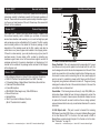
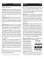
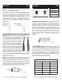
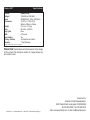
American DJ
®
Illusion 250™
General Information
Unpacking: Thank you for purchasing the Illusion 250™ by American
DJ®. Every Illusion 250™ has been thoroughly tested and has been
shipped in perfect operating condition. Carefully check the shipping
carton for damage that may have occurred during shipping. If the
carton appears to be damaged, carefully inspect your fixture for any
damage and be sure all equipment necessary to operate the unit has
arrived intact. In the event damage has been found or parts are missing, please contact our toll free customer support number for further
instructions. Please do not return this unit to your dealer without contacting customer support first.
Introduction: The Illusion 250™ is a four channel, intelligent DMX
fixture, that creates a bright, and awesome kaleidoscope effect, using
multiple gobos and colors. The fixture can operate in three different
operating modes; stand alone, sound-active, or in a Master/Slave configuration. The Illusion 250™ comes with several built in programs and
is best used in multiples of four. When used as a stand alone unit or
when used in multiples linked in a master/slave configuration. For best
results use fog or special effects smoke to enhance the beams projections.
During the initial start-up or use of this product a light smoke or
smell may arise from the unit. This is a normal process and is
cause by the heat associated with the lamp.
Customer Support: American DJ® provides a toll free customer
User Instructions
support line, to provide help and to answer any question should you
encounter problems during your set up or initial operation. You may
also visit us on the web at www.americandj.com for any comments or
suggestions. Service Hours are Monday through Friday 9:00 a.m. to 5:
00 p.m. Pacific Standard Time.
Voice:
(800) 322-6337
Fax:
(323) 582-2610
E-mail:
[email protected]
To purchase parts online visit http://parts.americandj.com
Warning! To prevent or reduce the risk of electrical shock or fire, do
12/04
American DJ®
4295 Charter Street
Los Angeles CA. 90058
www.americandj.com
not expose this unit to rain or moisture.
Warning! This may cause severe eye damage. Avoid looking directly
into the light source at all times!
American DJ® - www.americandj.com - Illusion 250™ Instruction Manual Page 2
Illusion 250™
Safety Precautions
Illusion 250™
Handling Precautions
For Your Own Personal Safety, Please Read and Understand This
Manual Completely Before You Attempt To Install Or Operate
This Unit!
• To reduce the risk of electrical shock or fire, do not expose this unit
rain or moisture
• Do not spill water or other liquids into or on to your unit.
• Be sure that the local power outlet match that of the required voltage for your unit.
• Do not attempt to operate this unit if the power cord has been
frayed or broken.
• Do not attempt to remove or break off the ground prong from
the electrical cord. This prong is used to reduce the risk of electrical
shock and fire in case of an internal short.
• Disconnect from main power before making any type of connection.
• Do not remove the cover under any conditions. There are no user
serviceable parts inside.
• Never operate this unit when it’s cover is removed.
• Always be sure to mount this unit in an area that will allow proper
ventilation. Allow about 6” (15cm) between this device and a wall.
• Do not attempt to operate this unit, if it becomes damaged.
• This unit is intended for indoor use only, use of this product outdoors voids all warranties.
• Always mount this unit in safe and stable matter.
• Power-supply cords should be routed so that they are not likely to
be walked on or pinched by items placed upon or against them,
paying particular attention to cords at plugs, convenience receptacles, and the point where they exit from the appliance.
• Cleaning -The fixture should be cleaned only as recommended by
the manufacturer. See page 15 for cleaning details.
• Heat -This fixture should be situated away from heat sources such
as radiators, heat registers, stoves, or other appliances (including
amplifiers) that produce heat.
• The fixture should be serviced by qualified service personnel when:
A. Objects have fallen, or liquid has been spilled into the appliance.
B. The appliance has been exposed to rain or water.
C. The appliance does not appear to operate normally or exhibits a
marked change in performance.
Caution! There are no user serviceable parts inside this unit. Do not
American DJ® - www.americandj.com - Illusion 250™ Instruction Manual Page 3
American DJ® - www.americandj.com - Illusion 250™ Instruction Manual Page 4
attempt any repairs yourself, doing so will void your manufactures
warranty. In the unlikely event your unit may require service please
contact American DJ®.
During operation the housing may become extremely hot. Avoid
touching the unit with bare hands while in use.
American DJ® will not accept any liability for any resulting damages
caused by the non-observance of this manual or any unauthorized
modification to this unit.
Illusion 250™
Halogen Lamp Warning
This fixture is fitted with a discharge lamp which
is highly susceptible to damage if improperly
handled. Never touch the lamp with your bare fingers as the oil from your hands will shorten lamp
life. Also, never move the fixture until the lamps
have had ample time to cool. Remember, lamps
are not covered under warranty conditions.
This unit emits intense UV radiation which is harmful to the eyes and
skin. The intense luminance of the lamp can cause severe damage
to the retina. Never operate this unit without it’s covers, these covers
have been specially designed to shield against UV radiation.
Epileptic Warning: Those suffering from epilepsy should avoid looking
directly into the lamp at all times.
Avoid switching the fixture on and off repeatedly in short intervals as
this will reduce lamp life and intensity.
To achieve the intensity associated with discharge lamps, these lamps
use gas sealed in a high pressure environment to emit a brilliant output.
Due to the high pressure involved with the construction of the lamp,
the lamp may explode during prolonged extensive use. This risk is
increased with age, added care is encouraged when dealing with older
lamps. Extreme caution should be used when operating this or any
fixture fitted with a gas discharge lamp. Never open this unit while in
use.
Illusion 250™
General Instructions
To optimize the performance of this product, please read these operating
instructions carefully to familiarize yourself with the basic operations of
this unit. These instructions contain important safety information regarding the use and maintenance of this unit. Please keep this manual with
the unit, for future reference.
Illusion 250™
Product Registration
The Illusion 250™ carries a one year limited warranty. Please fill out
the enclosed warranty card to validate your purchase. All returned
service items whether under warranty or not, must be freight pre-paid
and accompany a return authorization (R.A.) number. The R.A. number
must be clearly written on the outside of the return package. A brief
description of the problem as well as the R.A. number must also be
written down on a piece of paper and included in the shipping carton.
If the unit is under warranty, you must provide a copy of your proof of
purchase invoice. You may obtain a R.A. number by contacting our
customer support team on our toll free customer support number. All
packages returned to the service department not displaying a R.A.
number on the outside of the package will be returned to the shipper
at the shippers cost.
Illusion 250™
•
•
•
•
•
•
•
•
•
Features
Micro-Stepping Motors for Smooth Color and Gobo Transitions
DMX-512 Protocol Compatible (Uses Four DMX Channels)
3 Operating Modes - Master/Slave; Stand Alone; Sound Active
Combined Color/Gobo Wheel
Internal Microphone
ZB-MSD250/2 Discharge Lamp, 250w 2000 Hours
Manual Focus Lens
Variable Strobe
Mini/C Input Jack for Blackout Function
(Mini/C Controller Not Included)
American DJ® - www.americandj.com - Illusion 250™ Instruction Manual Page 5
Illusion 250™
Controls and Functions
9
8
7
6
5
4
1
2
3
1. Power Cord Inlet and Fuse Holder
Power Cord Inlet - This unit is equipped with a removable I.E.C. power
cord. Be sure to only use the power cord included with the unit, this
cord is designed to match the electrical requirements of the unit. Other
cords may cause the unit to overheat or malfunction. Voltage may vary
from venue to venue, when connecting this unit to a power supply be
sure to connect to a matching power outlet. Never use this fixture if
the ground prong has been removed or broken off. The ground prong
is designed to reduce the risk of fire or electrical shock in the event the
unit suffers from an internal short.
Fuse Holder - This housing stores a 8 amp (4 amp 220v) GMA protective fuse. Never defeat the fuse, the fuse is designed to protect the
electronics in the event of severe power fluctuations. Always be sure
to replace the fuse with an exact match as the one being replaced,
unless otherwise told to do so by an authorized American DJ® service
technician.
2. XLR Output Jack - This jack is used to transmit the incoming
DMX signal to another DMX fixture, or transmit a Master/Slave signal
to the next Illusion 250™ in the chain. For best results in DMX or
Master/Slave mode terminate this jack if it is the last unit in the chain.
See “Terminator” on page 10.
American DJ® - www.americandj.com - Illusion 250™ Instruction Manual Page 6
Illusion 250™
Controls and Functions
3. XLR DMX Input Jack - This jack is used to receive an incoming
DMX signal or Master/Slave signal.
4. Dipswitches - These switches serve two functions. In master-slave
mode these switches are used to assign a specific head address. In
DMX mode these switches are used to assign a DMX address to the
unit. In DMX mode each switch corresponds to a specific value based
on binary code. See pages 8-10 for a detailed explanation of DMX
binary code.
5. Audio Sensitivity Knob - This will adjust the audio sensitivity of the
INTERNAL MICROPHONE. Turning the sensitivity knob in the clockwise direction will increase the sensitivity to sound. Turning the knob
in the counter clockwise direction will decrease the fixture’s sensitivity
to sound.
6. MINI/C Controller Jack - This jack is for use with the optional
MINI/C controller only. This controller is used to control the blackout
function. Do not attempt to connect an audio signal to this jack, this
will damage the PC board and void your manufactures warranty!
7. Lamp Assembly and Access Plate - This plate accesses the lamp
socket assembly. The unit includes a spring mounted ZB-MSD250/2
250w discharge lamp. Be sure to only replace with same type lamp.
After replacing a lamp be sure the lamp is centered in the reflector.
See pages 13-14 for details on installing and optimizing replacement
lamps. Never operate this unit with the lamp exposed, this lamp emits
strong UV radiation.
8. Cooling Fan - This unit is equipped with three high velocity variable
fans to aid in the cooling process. These fans are designed to vary their
velocity at different operating temperatures, to provide better cooling
when the unit reached higher operating temperatures associated with
long usage. Be sure to never obstruct the cooling fans during normal
usage. Also, be sure to keep the vents clean at all times. A blocked or
malfunctioning cooling system may shorten lamp life and unit reliability.
9. Lens Assembly - This high quality lens is a fully focusing. Focus the
lens by manually turning the lens in a clockwise or counter-clockwise
direction until the desired effect is achieved.
American DJ® - www.americandj.com - Illusion 250™ Instruction Manual Page 7
Illusion 250™
Set Up
Power Supply: Before plugging your unit in, be sure the source voltage in your area matches the required voltage for your American DJ®
Illusion 250.™ The American DJ® Illusion 250™ is available in a 120v
and 220v version. Because line voltage may vary from venue to venue,
you should be sure your unit voltages matches the wall outlet voltage
before attempting to operate you fixture.
DMX-512: DMX is short for Digital Multiplex. This is a universal protocol used as a form of communication between intelligent fixtures
and controllers. A DMX controller sends DMX data instructions from
the controller to the fixture. DMX data is sent as serial data that travels from fixture to fixture via the DATA “IN” and DATA “OUT” XLR terminals located on all DMX fixtures (most controllers only have a DATA
“OUT” terminal).
DMX Linking: DMX is a language allowing all makes and models of
different manufactures to be linked together and operate from a single controller, as long as all fixtures and the controller are DMX compliant. To ensure proper DMX data transmission, when using several
DMX fixtures try to use the shortest cable path possible. The order
in which fixtures are connected in a DMX line does not influence the
DMX addressing. For example; a fixture assigned a DMX address of 1
may be placed anywhere in a DMX line, at the beginning, at the end,
or anywhere in the middle. When a fixture is assigned a DMX address
of 1, the DMX controller knows to send DATA assigned to address 1
to that unit, no matter where it is located in the DMX chain.
Dip-switches in DMX mode: This unit uses dip switches to assign a
DMX address. Each dip switch represents a binary value.
Dip Switch 1 address equals 1
DMX CHANNEL
Dip Switch 2 address equals 2
2
8 32 128 SF
Dip Switch 3 address equals 4
Dip Switch 4 address equals 8
Dip Switch 5 address equals 16
ON
Dip Switch 6 address equals 32
1 2 3 4 5 6 7 8 9 10
Dip Switch 7 address equals 64
Dip Switch 8 address equals 128
1 4 16 65 256
Dip Switch 9 address equals 256
Dipswitches 10, 11, and 12 - Some units omit dipswitch 10, and most
units do not have dipswitches 11 and 12. When a unit does include
American DJ® - www.americandj.com - Illusion 250™ Instruction Manual Page 8
Illusion 250™
Set Up
Illusion 250™
dipswitch 10 it is usually used for special functions such as sound
activation or in this case pan/tilt inversion.
Each dip switch has a preset value. A specific DMX address is set by
combining the dip switches that sum your desired value. For example: To achieve a DMX address of 21, combine dip switches 1, 3, and
5. Sense dip switch 1 has a value of 1, dip switch 3 has a value of 4,
and dip switch 5 has a value of 16, the combination of the create a
DMX value of 21.
REMOTE
CONTROL
INPUT
SOUND
Set DMX address 21:
Dip-switches # 1 = 1
3=4
5 = 16
= 21
INPUT
OUTPUT
REMOTE
CONTROL
INPUT
SOUND
3
REMOTE
CONTROL
INPUT
SOUND
INPUT
POWER
OUTPUT
POWER
COMMON
DMX512 OUT
3-PIN XLR
1
3
2
DMX +
DMX -
1
3
2
1
DMX512 IN
3-PIN XLR
Pin 1 = Ground
REMOTE
OUTPUT
INPUT
OUTPUT
PinCONTROL
2
= Data Compliment (negative)
INPUT
SOUND
3 Hot
Pin 3 = Data True (positive)
Special Note: Line Termination. When longer runs of cable are
used, you may need to use a terminator on the last unit to avoid erratic
behavior. A terminator is a 90-120 ohm 1/4 watt resistor which is connected between pins 2 and 3 of a male XLR connector (DATA + and
DATA -). This unit is inserted in the female XLR connector of the last
unit in your daisy chain to terminate the line. Using a cable terminator
(ADJ part number Z-DMX/T) will decrease the possibilities of erratic
behavior.
1
3
2
OUTPUT
XLR Pin Configuration
1 Ground
Figure 3
1=1
4 DMX512
=8
DMX+,DMX-,COMMON
7 = 64
8 = 128
= 201
INPUT
INPUT
3 Hot
1
REMOTE
CONTROL
INPUT
2 Cold
2 Cold
POWER
Data Cable (DMX Cable) Requirements (For DMX and Master/Slave
Operation): The Illusion 250™ can be controlled via DMX-512 protoCOMMON
col. The Illusion 250™ is a four channel DMX unit. The DMX address
is
DMX +
DMX512 OUT
set on the bottom panel of the Illusion 250.™ Your
3-PIN XLR
DMX unit and your DMX controller require a standard 3pin XLR connector for data input and data output
(Figure 1). If you are making your own cables, be
sure to use standard two conductor shielded cable
(This cable may be purchased at almost all pro
sound and lighting stores). Your cables should be
made with a male and female XLR connector on
Figure 1
either end of the cable. Also remember that DMX cable must be daisy
chained and can not be split.
Notice: Be sure
toDMX512
follow figures two and three when making your own
DMX+,DMX-,COMMON
cables. Do not use the ground lug on the XLR connector. Do not connect the cable’s shield conductor to the ground lug or allow the shield
conductor to come in contact with the XLR’s outer casing. Grounding
the shield could cause a short circuit and erratic behavior.
SOUND
XLR Female Socket
XLR Male Socket
1 Ground
POWER
Set DMX address 201:
Dip-switches #
Set Up
3
2
Figure 2
American DJ® - www.americandj.com - Illusion 250™ Instruction Manual Page 9
2
SOUND
1
DMX512 IN
3-PIN XLR
3
2
REMOTE
CONTROL
INPUT
INPUT
POWER
Termination reduces signal errors and
avoids signal transmission problems
and interference. It is always advisable
to connect a DMX terminal, (Resistance
120 Ohm 1/4 W) between PIN 2 (DMX-)
and PIN 3 (DMX +) of the last fixture.
Figure 4
OUTPUT
5-Pin XLR DMX Connectors. Some manufactures use 5-pin XLR
connectors for DATA transmission in place of 3-pin. 5-pin XLR fixtures
may be implemented in a 3-pin XLR DMX line. When inserting standard 5-pin XLR connectors in to a 3-pin line a cable adaptor must be
used, these adaptors are readily available at most electric stores. The
chart below details a proper cable conversion.
POWER
3-Pin XLR to 5-Pin XLR Conversion
Conductor
3-Pin XLR Female (Out)
5-Pin XLR Male (In)
Ground/Shield
Pin 1
Pin 1
Data Compliment (- signal)
Pin 2
Pin 2
Termination reduces signal errors
and
Data
True (+ signal)
avoids signal transmission problems
and interference. It is always advisable
Not
Used
to connect a DMX terminal, (Resistance
120 Ohm 1/4 W) between PIN 2 (DMX-)
and PIN 3 (DMX +) of the last fixture.
Not Used
Pin 3
Pin 3
Pin 4 - Do Not Use
Pin 5 - Do Not Use
American DJ® - www.americandj.com - Illusion 250™ Instruction Manual Page 10
Illusion 250™
Operation
Operating Modes: The Illusion 250™ can operate in three different modes. This next section will detail the differences in the
operating modes.
• Stand alone mode The unit will react to sound, chasing through the built-in programs.
You can also use the optional MINI/C Remote Control to blackout the
units.
• Master/Slave mode You can daisy chain up to 16 units together to get a synchronized
light show without the need of an external controller. The units will
react to sound chasing through the several built-in programs.
• DMX control mode This function will allow you to control each individual fixtures traits
with a standard DMX-512 controller such as the Elation ® Show
Designer.™
Universal DMX Control: This function allows you to use a universal DMX-512 controller such as the Elation® DMX Operator™
or Elation® Show Designer™ to control the color/gobo wheel, the
prism, the shutter (strobe), and the Internal programs. A DMX controller allows you to create unique programs tailored to your individual
needs.
1. The Illusion 250™ uses four DMX channels. Channel 1 controls
the color/gobo wheel, channel 2 controls the prism rotation,
channel 3 controls the shutter/strobe, and channel 4 selects one
of the 10 internal program. See page 16-17 for detailed description of the DMX traits.
2. To control your fixture in DMX mode, follow the set-up procedures
on pages 8-10 as well as the set-up specifications that are
included with your DMX controller.
3. Use the controller’s faders to control the various DMX fixture traits.
4. This will allow you to create your own programs.
5. For longer cable runs (more than a 100 feet) use a terminator on
the last fixture.
6. For more help operating in DMX mode consult the manual included with your DMX controller.
Illusion 250™
Operation
1. To operate the unit in Sound Active mode. “Flip” dipswitch #10 to
the “on” position.
2. The Illusion 250™ will now react to the bass sound of music via
the internal microphone.
Stand Alone Mode (Internal Program):
1. To operate as a stand alone unit, via its internal program, “flip”
dipswitch #12 to the “on” position.
2. The Illusion 250™ will now run its own internal program.
3. You can also use the optional MINI/C Remote Control to activate
the blackout function.
Master-Slave Operation: This function will allow you to link up to
16 units together and operate without a controller. The units can be
sound activate or run the Internal program. In Master-Slave operation
one unit will act as the controlling unit and the others will react to
the controlling units movements and programs. Any unit can act as a
Master or as a Slave.
1. Using standard XLR microphone cables, daisy chain your units
together via the XLR connector on the rear of the units. Remember the Male XLR connector is the input and the Female XLR
connector is the output. The first unit in the chain (master) will use
the female XLR connector only - The last unit in the chain will use
the male XLR connector only. For longer cable runs we suggest a
terminator at the last fixture.
2. Designate one unit to be the Master by ‘flipping” dipswitch #11 to
the “on” position.
3. On the Slave units, leave all dipswitches in the “off” position.
4. For Sound Active mode, “flip” dipswitch #10 to the “on” position,
on the Master unit.
5. You can also use the optional MINI/C Remote Control to activate
the blackout function. If you want to use the optional remote control, connect the MINI/C controller to the first fixture in the line
(master)
Stand-Alone Operation (Sound Active): This mode allows a single
unit or several units linked together, to run to the beat of the music.
American DJ® - www.americandj.com - Illusion 250™ Instruction Manual Page 11
American DJ® - www.americandj.com - Illusion 250™ Instruction Manual Page 12
Illusion 250™
Fuse & Lamp Replacement
Illusion 250™
Fuse & Lamp Replacement
Caution: Always replace with the exact same type lamp and fuse,
unless otherwise specified by an authorized American DJ® service
technician. Replacing with anything other than the specified part can
damage your unit and will void your manufactures warranty.
Optimizing Lamp Alignment: This procedure centers the lamp in
the reflector. Proper optimization will increase lamp life and ensure a
bright crisp output. Improper optimization may add a yellow tint to the
lamp output and reduce intensity.
Warning: If you continue to blow lamps or fuses, STOP using the
1. Be sure main power is disconnected and allow the unit to cool. If
the you have just installed a new unit you can obviously skip this
step.
2. Make a preliminary adjustment: Turn the three lamp adjustment
thumb screws completely in (clockwise). Then back them each
out (counter-clockwise) about three complete turns.
3. Turn the unit on and allow it to reset.
4. Using either a DMX controller or the control panel on the unit,
strike the lamp and focus the light on a flat surface.
5. Center the hot-spot (the brightest part of the beam) using the 3
adjustment screws. Turn one screw at a time to drag the hot-spot
diagonally across the projected image. If you cannot detect a hotspot, adjust the lamp until the light is even.
6. To reduce a hot-spot, pull the lamp in by turning all three screws
clockwise 1/4-turn at a time until the light is evenly distributed.
7. If the light is brighter around the edge than it is in the center, or if
light output is low, the lamp is too far back in the reflector. “Push”
the lamp out by turning the screws.
unit. Contact customer support for further instructions, you may have
to return the unit for servicing. Continuing to use the unit may cause
serious damage.
Lamp Replacement: Caution! Never attempt to change the lamp
while the fixture is plugged in. Always disconnect the main power
and allow the unit ample time to cool before attempting to replace
the lamp. Lamp replacement has been made simple by incorporating
a slide out lamp assembly that is retained by two phillips screws.
1. Be sure to follow the proper handling procedures that deal with
discharge lamps.
2. Remove the two small screws (A,B) on the rear of the unit
3. After removing the screws, gently slide out the socket assembly
from the rear of the unit to expose the lamp.
4. Carefully remove the old lamp and discard it in the trash.
5. Replace the lamp with an exact match and reassemble in reverse
order.
6. After replacing the lamp follow the optimization procedures on the
next page to be sure the lamp is center in the reflector
A
B
Optimizing Screws
Optimizing Screws
Fuse Replacement: Locate and remove the unit’s power cord. Once
the cord has been removed located the fuse holder located inside the
power socket. Insert a flat-head screw driver into the power socket
and gently pry out the fuse holder. Remove the bad fuse and replace
with a new one. The fuse holder has a built-in socket for a spare fuse
be sure not to confuse the spare fuse with active fuse.
American DJ® - www.americandj.com - Illusion 250™ Instruction Manual Page 13
American DJ® - www.americandj.com - Illusion 250™ Instruction Manual Page 14
Illusion 250™
Cleaning
Fixture Cleaning: Due to fog residue, smoke, and dust cleaning the
internal and external optical lenses and mirror should be carried out
periodically to optimize light output. Cleaning frequency depends on
the environment in which the fixture operates (I.e. smoke, fog residue,
dust, dew). In heavy club use we recommend cleaning on a monthly
basis. Periodic cleaning will ensure longevity, and crisp output.
1. Use normal glass cleaner and a soft cloth to wipe down the outside casing.
2. Use a brush to wipe down the cooling vents and fan grill.
3. Clean the external optics and mirror with glass cleaner and a soft
cloth every 20 days.
4. Clean the internal optics with glass cleaner and a soft cloth every
30-60 days.
5. Always be sure to dry all parts completely before plugging the unit
back in.
Illusion 250™
Illusion 250™
Channel
Value
No light output from the unit;
1. Be sure you have connected your unit into a standard 120v wall
outlet.
2. Be sure the external fuse has not blown. The fuse is located on
the bottom panel of the unit.
3. Remove the lamp holder and be sure the lamp is seated in its
socket properly. Occasionally lamps become loose during shipping be sure the lamp is push in to its socket all the way.
4. Be sure the fuse holder is completely and properly seated.
Unit does not respond to sound;
1. Low frequencies (bass) should cause the unit to react to sound.
Tapping on the microphone, quiet or high pitched sounds may
not activate the unit.
Function
1
COLOR WHEEL
0 - 127
128 - 187
188 - 193
194 - 255
COLOR INDEXING
FORWARDS RAINBOW EFFECT
FAST
SLOW
NO ROTATION
BACKWARDS RAINBOW EFFECT
SLOW
FAST
2
PRISM ROTATION
0-7
8 - 127
128 - 135
136 - 255
Trouble Shooting
Trouble Shooting: Listed below are a few common problems that
you may encounter, with solutions.
DMX Traits
NO ROTATION
FORWARDS PRISM ROTATION
FAST
SLOW
NO ROTATION
BACKWARDS PRISM ROTATION
SLOW
FAST
3
SHUTTER & STROBE
0-3
4-7
8 - 31
32 - 63
64 - 95
96 - 127
128 - 159
160 - 191
192 - 223
224 - 255
SHUTTER CLOSED
SHUTTER CLOSED & MOTOR RESET
SHUTTER CLOSED
DIMMER (CLOSED TO OPEN)
STROBE EFFECT
SLOW
FAST
NO FUNCTION (SHUTTER OPEN)
PULSE EFFECT IN SEQUENCES
NO FUNCTION (SHUTTER OPEN)
STROBE EFFECT
SLOW
FAST
NO FUNCTION (SHUTTER OPEN)
Continued on the Next Page
American DJ® - www.americandj.com - Illusion 250™ Instruction Manual Page 15
American DJ® - www.americandj.com - Illusion 250™ Instruction Manual Page 16
Illusion 250™
Channel
Value
4
DMX Traits cont.
Function
BUILT-IN PROGRAMS
0 - 23
24 - 47
48 - 71
72 - 95
96 - 119
120 - 143
144 - 167
168 - 191
192 - 215
216 - 239
240 - 255
NORMAL
AUTO PROGRAM 1
AUTO PROGRAM 2
AUTO PROGRAM 3
AUTO PROGRAM 4
AUTO PROGRAM 5
AUTO PROGRAM 6
AUTO PROGRAM 7
AUTO PROGRAM 8
AUTO PROGRAM 9
AUTO PROGRAM 10
Illusion 250™
Warranty
1-YEAR LIMITED WARRANTY
A. American DJ® hereby warrants, to the original purchaser, American DJ® products to be
free of manufacturing defects in material and workmanship for a period of 1 Year (365 days)
from the date of purchase. This warranty shall be valid only if the product is purchased
within the United States of America, including possessions and territories. It is the owner’s
responsibility to establish the date and place of purchase by acceptable evidence, at the
time service is sought.
B. For warranty service, send the product only to the American DJ® factory. All shipping
charges must be pre-paid. If the requested repairs or service (including parts replacement)
are within the terms of this warranty, American DJ® will pay return shipping charges only
to a designated point within the United States. If the entire instrument is sent, it must be
shipped in its original package. No accessories should be shipped with the product. If any
accessories are shipped with the product, American DJ® shall have no liability whatsoever
for loss of or damage to any such accessories, nor for the safe return thereof.
C. This warranty is void if the serial number has been altered or removed; if the product is
modified in any manner which American DJ® concludes, after inspection, affects the reliability of the product; if the product has been repaired or serviced by anyone other than
the American DJ® factory unless prior written authorization was issued to purchaser by
American DJ®; if the product is damaged because not properly maintained as set forth in
the instruction manual.
D. This is not a service contract, and this warranty does not include maintenance, cleaning
or periodic check-up. During the period specified above, American DJ® will replace defective parts at its expense, and will absorb all expenses for warranty service and repair labor
by reason of defects in material or workmanship. The sole responsibility of American DJ®
under this warranty shall be limited to the repair of the product, or replacement thereof,
including parts, at the sole discretion of American DJ®. All products covered by this warranty were manufactured after January 1, 1990, and bear identifying marks to that effect.
E. American DJ® reserves the right to make changes in design and/or improvements upon
its products without any obligation to include these changes in any products theretofore
manufactured.
F. No warranty, whether expressed or implied, is given or made with respect to any accessory supplied with products described above. Except to the extent prohibited by applicable
law, all implied warranties made by American DJ® in connection with this product, including warranties of merchantability or fitness, are limited in duration to the warranty period
set forth above. And no warranties, whether expressed or implied, including warranties of
merchantability or fitness, shall apply to this product after said period has expired. The
consumer’s and or Dealer’s sole remedy shall be such repair or replacement as is expressly
provided above; and under no circumstances shall American DJ® be liable for any loss or
damage, direct or consequential, arising out of the use of, or inability to use, this product.
G. This warranty is the only written warranty applicable to American DJ® Products and
supersedes all prior warranties and written descriptions of warranty terms and conditions
heretofore published.
H. Lamps are not covered under this or any other warranty, either written or implied.
American DJ® - www.americandj.com - Illusion 250™ Instruction Manual Page 17
American DJ® - www.americandj.com - Illusion 250™ Instruction Manual Page 18
Illusion 250™
Model:
Voltage*:
Lamp:
Dimensions:
Weight:
Fuse:
Duty Cycle:
DMX:
Sound Active:
Working Position:
Warranty:
Specifications
Illusion 250™
120v/60Hz or 230v/50Hz
ZB-MSD250/2 250w 2000 Hours
14.25”(L) x 11”(W) x 9”(H)
360mm x 280mm x 228mm
27.5 Lbs. / 12.5 kgs.
8A (120v) / 4A (220v)
None
4 Channels
Yes
Any Safe, Secure Position
1 Year (365 days)
*Voltage is preset at the factory and is not user selectable
Please Note: Specifications and improvements in the design
of this unit and this manual are subject to change without any
prior written notice.
American DJ® - www.americandj.com - Illusion 250™ Instruction Manual Page 19
American DJ®
American DJ World Headquarters:
4295 Charter Street Los Angeles, CA 90058 USA
Tel: 323-582-2650 / Fax: 323-582-2610
Web: www.americandj.com / E-mail: [email protected]