1
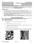
Edelbrock Shorty Headers
For 2005-2008 Ford Mustang GT
®
Catalog #65052 (Ceramic-Coated) &
#65053 (Ti-Tech Coated)
INSTALLATION INSTRUCTIONS
Please study these instructions carefully before installing your new Headers. If you have any questions, please contact our Technical
Hotline at : 1-800-416-8628 from 7 am - 5pm, Monday-Friday, Pacific Standard Time or e-mail us at
[email protected].
HEADERS: These components are designed to improve the exhaust efficiency of the Ford Mustang GT engine. This system does
not require welding for installation and retains all O.E.M. emissions equipment. These Edelbrock headers are street legal in all
50 states.
IMPORTANT NOTE:
Proper installation is the responsibility of the installer. Improper installation will void warranty and may result in
poor performance and engine or vehicle damage.
Suggested Tools Needed for Installation. This vehicle has metric fasteners:
❑ 3/8" and 1/4” ratchet socket set with extensions and universal 13mm and 15mm swivel sockets
❑ Set of combination wrenches
❑ Jack and jackstands, screwdrivers, pliers, crescent wrench, etc.
❑ Torque wrench
❑ Liquid penetrant, (GM #1052627) anti-seize compound (GM #5613695)
❑ Thread locking compount (Loctite)
SPECIAL NOTICE: This Edelbrock part has received an Executive Order number (E.O.#) from the California Air Resources Board
(C.A.R.B.) making it legal for street use in all 50 states. To assist you with emission equipment certification, we have included a silver
fan shroud decal to help testing personnel verify the this part is a legal replacement on the vehicle for which it is cataloged. The
adhesive-backed decal should be affixed next to the existing emission and engine specifications decal. Do not cover any part of your
original emission decal.
WARNING: The use of "Thermal Wrap" or any aftermarket coating process will void the warranty on your Edelbrock Headers.
Those products will cause excessive heat and moisture buildup resulting in corrosion and failure of the header.
IMPORTANT NOTE:
Anytime you are raising an engine inside the vehicle, make sure the hood is open and that there is proper clearance
for wires, fuel lines, and hoses. Always properly secure the engine while it is raised, as the engine could cause
bodily harm if improperly raised and secured.
INSTALLATION INSTRUCTIONS
DISASSEMBLY
1. Raise vehicle on a stable surface and place on
jackstands. Never only use the jack to hold up vehicle.
2. Disconnect negative battery cable from battery.
Note: Removal of battery and battery tray may make
installation easier.
3. Remove airbox assembly.
4. Disconnect all 4 oxygen sensors at pigtail connections.
5. Loosen clamps at rear of headpipe assembly and slide
clamps rearward until they are off headpipe.
©2007 Edelbrock Corporation
Catalog #65052, #65053
Page 1 of 2
6. Unbolt headpipe from exhaust manifolds. Slide
headpipe assembly to the rear of the vehicle until
hangers at transmission crossmember disengage.
7. Unbolt steering shaft at rack and pinion. Remove rack
and pinion retaining bolts from top of K-member. Do
not remove nuts on bottom of K-member as they are
welded on. Slide rack and pinion forward while slipping
steering shaft off of rack and pinion.
8. Remove starter.
9. Remove the nuts on the top of the motor mounts and
raise the engine approximately 3” - 4”.
10 Unbolt and remove the stock exhaust manifolds.
Brochure #63-0388
Rev. 10/07 - AJ/mc
HEADER INSTALLATION
1. Remove the passenger side aluminum motor mount.
2. Remove exhaust manifold studs from cylinder heads.
Clean manifold gasket surfaces of all gasket material.
3. Using supplied gaskets, 8mm bolts, lockwashers, and
black hardened washers, install only bottom bolts,
and washers to hold gasket in place. Leave bolts
loose so header flange can be slipped over the
hardware. Use anti-seize compound on all bolts.
4. Working from under vehicle, slip the right Edelbrock
shorty header up into place, taking care not to
damage gasket. Take your time and it will require
some maneuvering. Slide header down over the
manifold bolts.
5. From top of vehicle, install remaining right header
bolts, and washer on right header. Tighten header
bolts at this time, working from center bolts outward.
6. Reinstall the passenger side aluminum motor mount.
7. Remove the driver side aluminum motor mount.
8. Working from under vehicle, slip the left Edelbrock
shorty header up into place. Install oxygen sensor
from original left manifold before slipping header over
manifold bolts.
9. Install remaining left header bolts and washers from
the top of the vehicle. Tighten header bolts working
from center bolt out.
10. Reinstall the driver side aluminum motor mount and
set the engine back down on the mounts, then
retighten the top-mount nuts.
11.
12.
13.
14.
15.
16.
17.
18.
19.
20.
21.
22.
Note: Adjust the engine from side to side for proper
header clearance.
Install starter.
Slip rack and pinion back into place while sliding
steering shaft back onto rack and pinion. Torque
rack and pinion bolts to 40 ft. lbs. Install steering
shaft bolt using thread locking compount on
threads.
Install headpipe assembly in reverse of removal.
Install D-nut gaskets supplied onto header outlet.
Bolt headpipe to Edelbrock shorty headers using
supplied 3/8 bolts, lockwasher, and flatwashers.
Use anti-seize compound on threads and tighten,
using care not to crush D-nut gaskets.
Place rear exhaust pipe back into position and slip
clamp connectors onto headpipe. Tighten clamps at
this time.
Re-connect all oxygen sensors.
Install airbox assembly.
Check for proper clearance of all wires, cables, and
hoses from all exhaust components.
Re-connect battery.
Start vehicle and bring to normal operating
temperature. Check for exhaust leaks, and any
warning lights. Turn engine off and let it cool.
Re-tighten all exhaust bolts.
KIT CONTENTS
Qty.
1
1
2
2
16
16
16
4
4
4
Part #65052
(Ceramic-Coated)
Part #
Description
25-9469 Left Header
25-9470 Right Header
Port flange gaskets
D-Nut gaskets
Port flange bolts
Port flange flat washers (thick hardened)
Port flange lock washers
Collector flange bolts
Collector flange flat washers
Collector flange lock washers
Qty. Part #
1
25-9467
1
25-9468
2
2
16
16
16
4
4
4
-
Part #65053
(Ti-Tech Coated)
Description
Left Header
Right Header
Port flange gaskets
D-Nut gaskets
Port flange bolts
Port flange flat washers (thick hardened)
Port flange lock washers
Collector flange bolts
Collector flange flat washers
Collector flange lock washers
®
Edelbrock Corporation, 2700 California St., Torrance, CA 90503
Tech Line: 1-800-416-8628
E-Mail: [email protected]
©2007 Edelbrock Corporation
Catalog #65052, #65053
Page 2 of 2
Brochure #63-0388
Rev. 10/07 - AJ/mc