1
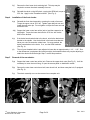
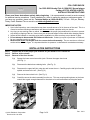
COIL OVER SHOCK
for 1992-2000 Honda Civic & 1994-2001 Acura Integra
Catalog # 33700, #34700 & #34701
INSTALLATION INSTRUCTIONS
PostScript Picture
(ShockLogo.eps)
Please read these instructions entirely before beginning. It is recommended to consult a service manual
for additional service procedures. Proper installation is a must to realize the maximum performance gains. If
you have any questions, please call our Technical Hotline at 1-800-416-8628, 7:00 am - 5:00 pm, MondayFriday, Pacific Standard Time or e-mail us at [email protected].
IMPORTANT NOTES:
1. Upon initial inspection, some new shocks may have a small amount of oil in the area of the seal. This is a
normal occurrence following manufacture and does not indicate a problem with your shocks.
2. Any time you are working under a vehicle, be sure to use the proper jack stands and tire chocks to prevent
any shifting or slipping of the car. Never use a jack as the sole support of the vehicle while changing shocks.
3. Inspect shock brackets or mounting points before installation to make sure they are not broken or bent.
4. Do not attempt to disassemble the Edelbrock IAS shocks. Contact your point of purchase or Edelbrock
for any necessary service or repairs.
5. Measure and record ride heights at all four corners before disassembly. The car must be on a flat level
surface with a full tank of gas. It is important that the tire pressure is checked and corrected as necessary.
INSTALLATION INSTRUCTIONS
Step 1
Step 2
Step 3
Support the car at the proper jack locations on jack stands or on a vehicle lift.
Remove all four wheels.
Removal of the front shocks:
3(a)
Support the lower control arm with a jack. Remove the upper shock nuts
(See Fig. 1).
3(b)
Disconnect the brake hose retaining bolts. (See Fig. 2).
3(c)
Disconnect the upper ball joint cotter pin and loosen the nut. Carefully pop the ball joint from the
spindle and remove the nut. (See Fig. 2).
3(d)
Remove the lower shock bolt. (See Fig. 2).
3(e)
Carefully remove the shock assembly from the car. This may require pushing down on the lower
control arm to gain enough clearance for the shock to be removed without touching the fender.
Fig. 2
Fig. 1
© 2001 Edelbrock Corporation
Brochure No. 84-8158
Page 1 of 4
Rev. 10/01
Step 4
3(f)
Remove the front lower clevis retaining bolt. This step may be
required to remove the shock assembly from car.
3(g)
Reinstall the clevis on the IAS shock, reusing the OEM bolt, torque to
35 ft. lbs. Apply Loctite Threadlocker #262. (See Fig. 3).
Installation of the front shocks:
4(a)
Reinstall the front shock assembly, reversing the order of removal.
Torque the upper nuts to 35 ft. lbs. Tighten upper ball joint nut and
install the new cotter pin. Do not tighten or torque the lower nut and
bolt at this time.
4(b)
Support the lower control arm with a jack to load the suspension at
ride height. Torque the lower clevis bolt to 35 ft. lbs. with Loctite
#262 on the threads.
4(c)
If the brake hose bracket bolts to the shock, wire tie the brake hose
bracket to the spindle. Use the bolt hole in the brake hose bracket.
Never put a wire tie around a rubber hose. On some models, the
brake hose attaches to the clevis. If so, use the OEM hardware.
(See Fig. 4).
(d)
Step 5
Fig. 3
The coil over threaded collar is pre-adjusted to lower the car approximately 1 1/4" - 1 1/2". Due
to the differences in equipment and vehicle weight, the threaded collars may require adjusting to
obtain the desired final ride height. Step 7 covers this procedure.
Removal of the rear shocks:
5(a)
Support the lower control arm with a jack. Remove the upper shock nuts (See Fig. 5). It will be
necessary to move the trunk lining, or open the access panel on hatchback models.
5(b)
Remove the outer lower control arm bolt, lower shock bolt, and lower sway bar bolt, if equipped.
(See Fig. 6).
5(c)
The shock assembly can now be removed as a complete unit.
Fig. 4
© 2001 Edelbrock Corporation
Brochure No. 84-8158
Fig. 5
Page 2 of 4
Fig. 6
Rev. 10/01
Step 6
Installation of the rear shocks:
6(a)
The Edelbrock IAS rear shock is assembled and does not require the reuse of OEM components.
The coil over is pre-adjusted for approximately 1 1/4" - 1 1/2" drop. Due to the differences in
equipment and vehicle weight, the threaded collars may require adjusting to achieve your desired
final ride height. See step # 7. (See Fig. 7).
Fig. 7
Step 7
6(b)
Reinstall the rear shock assembly reversing the order of removal. Torque the upper nuts 35 ft. lbs.
Do not tighten or torque the lower nut and bolt at this time.
6(c)
Support the lower control arm with a jack to load the
suspension at ride height. Torque the lower clevis bolt
to 35 ft. lbs. with Loctite #262 applied to the threads.
6(d)
If the car is equipped with rear disc brakes, the brake
hose support clamp needs to be removed and
reinstalled upside down to gain clearance for the coil
spring. (See Fig. 8).
Fig. 8
Adjusting the ride height of coil over shocks:
The Edelbrock IAS coil over shock assemblies are shipped assembled and are adjusted to lower your car
approximately 1 1/4" - 1 1/2". They may require adjusting the coil over collars in order to achieve the
desired ride height.
The car must be assembled, driven and measured before adjusting the ride height.
If the ride height needs to be adjusted, proceed as follows:
7(a) Support the car at the proper jack locations, with jack stands or on a lift. Remove the wheels.
7(b)
The front adjusting collar may require the loosening and popping of the upper ball joint in order to
access and rotate the adjusting collar.
7(c)
The setscrew needs to be loosened before the collar can be rotated. To lower the car, rotate the
collar up (effectively relaxing the spring preload). The collars should be adjusted the same amount
side to side. The collar measurements should be recorded along with the installed ride heights
before and after changes.
7(d)
The ride height should not be adjusted more than 1/2" at the collar per adjustment. Moving
the collar 1/2" will change the ride height approximately 1/2" - 3/4" depending on the direction the
collar is moved.
7(e)
If the car does not measure square, and you have checked the installation, and everything is
installed correctly, the individual collars can be adjusted to make the ride height even.
7(f)
After making ride height adjustments, the car must be reassembled and driven in order to settle the
suspension. This is the best way to obtain an accurate ride height measurement.
© 2001 Edelbrock Corporation
Brochure No. 84-8158
Page 3 of 4
Rev. 10/01
Step 8 Final Procedures:
8(a)
The wheels must be torqued at the manufacturer's recommended specifications.
8(b)
All four wheels must be aligned by an alignment shop for the best handling and tire wear.
Note:
After car has been driven, the wheel torque must be checked. The springs and brake hoses must
be inspected to ensure that there is no contact that can cause any damage. All nuts and bolts
must also be inspected.
Enjoy the improved ride and handling from your new Edelbrock IAS shocks.
Edelbrock Corporation
2700 California St.
Torrance, CA 90503
Toll-Free Tech Line (800) 416-8628
Tech Fax (310) 972-2730
Tech E-Mail: [email protected]
© 2001 Edelbrock Corporation
Brochure No. 84-8158
Page 4 of 4
Rev. 10/01