1
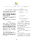
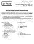
VICTOR VORTEC EFI INTAKE MANIFOLD
for Small-Block Chevy with Vortec-Style Cylinder Heads
Catalog #29135 & #29136
INSTALLATION INSTRUCTIONS
PLEASE study these instructions carefully before beginning this installation. Most installations can be accomplished with common tools and
procedures. However, you should be familiar with and comfortable working on your vehicle. If you do not feel comfortable performing this
installation, it is recommended to have the installation completed by a qualified mechanic. If you have any questions, please call our Technical
Hotline at: 1-800-416-8628, 7:00 am - 5:00 pm, Pacific Standard Time, Monday through Friday or e-mail us at [email protected].
IMPORTANT NOTE: Proper installation is the responsibility of the installer.
Improper installation may result in poor performance and engine or vehicle damage.
PLEASE complete and mail your warranty card. Be sure to write the model number of this product in the "Part #____" space. THANK YOU.
DESCRIPTION: The Edelbrock Victor Vortec 29135 EFI intake manifold retains the same features as our 2913 intake manifold, with the addition
of machined vertical injector bosses (The injector bosses are located on top of the runners for optimum performance). The 29135 is designed to
fit factory 1996 and later Vortec or Vortec type cylinder heads such as Fast Burn or E-Tec for small block Chevrolet engines. The runner design
delivers maximum power from 3500-8000 rpm. The 29135 accepts standard square-bore flange throttle bodies. 29135 is an intake manifold
only. The 29136 includes a Fuel Rail Kit (See Below).
NOTE: This manifold is not intended, nor legal, for street use on pollution-controlled vehicles. Furthermore, It is the
responsibility of the end-user to verify conformity to any particular racing association's rules regarding manifold
dimensions, aligning to a template, etc.
•
FUEL RAIL KIT CONTENTS (Included with #29136):
❑
❑
❑
❑
•
2 - Machined fuel rail extrusions (fuel rail ends tapped for 3/8" pipe)
4 - Tall version fuel rail bracket stands (2.65" o-ring spacing)
4 - Short version fuel rail bracket stands (1.5" o-ring spacing)
4 - 1/4-20 x ½" Socket head bolts
❑ 4 - 1/4-20 x 1-1/2" Hex head bolts
❑ 12 - 1/4" Flat washers
❑ 4 - 1/4-20 Nyloc Hex nuts
ACCESSORIES & INSTALLATION ITEMS: Major recommendations are listed below. However, due to the variety of applications, additional
equipment may be required for your specific vehicle than mentioned in these instructions.
MANIFOLD
THROTTLE BODY TYPE
PART NUMBER AND DESCRIPTION
29135
Standard Square-Bore Style Base
P/N 3878 - 1000 CFM With Standard GM/Delphi IAC
P/N 38783 - 1000 CFM With MotoTron/Hitachi Linear-Style IAC
NOTE: Some applications may benefit from the use of a one-inch carburetor spacer under the throttle body, such as Edelbrock
#8710. See our Catalog for details. To order a catalog, call (800) FUN-TEAM.
•
GASKETS: Do not use competition style intake gaskets for this intake manifold. Due to material deterioration over time, internal leakage of
vacuum, oil, and coolant may occur.
INTAKE MANIFOLD
NOTES
RECOMMENDED GASKET
29135
C
Edelbrock #7235 Port: 1.08” x 2.11”, .120” Thickness
C - Does Not Have Embossed Silicone Bead
NOTE: To ensure maximum performance and a proper seal, Edelbrock gaskets which are
specifically designed and manufactured for use with Edelbrock parts must be used.
Catalog #s 29135, 29136
Rev. 12/05 - RS/mc
Page 1 of 2
©2005 Edelbrock Corporation
Brochure #63-0474
•
INJECTOR WARNING: It is important to select the appropriate electronic injectors for optimum performance. The injectors must not only
match the fuel demands of an engine, but they must also meet the electronic commands of the engine control unit (ECU). Once injectors and
an ECU is determined, make sure that when installing the injectors onto the manifold, that the o-rings of the injectors create a complete seal
to prevent any air or fuel from leaking out. The same precaution should be applied when assembling the injectors to the fuel rails.
•
POWER OPTIONS: Although this manifold will work with ported factory cast iron heads, we highly recommend the use of our #60979 or
60989 Performer RPM E-Tec cylinder heads. These heads offer higher airflow levels with minimum preparation required. See our catalog
for details. We also recommend port matching the intake manifold .020” smaller than the gasket, or cylinder head, whichever is smaller.
INSTALLATION PROCEDURE
•
INTAKE MANIFOLD INSTALLATION:
1.
Use only recommended intake gaskets set when installing this intake
manifold.
2.
Fully clean the cylinder head intake flanges and the engine block end
seal surfaces.
3.
Apply Edelbrock Gasgacinch sealant P/N 9300 to both cylinder head
flanges and to the cylinder head side of the gaskets, allow to air dry,
and attach the intake gaskets.
4.
Do not use cork or rubber end seals. Use RTV silicone sealer instead.
Apply a ¼" high bead across each block end seal surface,
overlapping the intake gasket at the four corners. This method will
eliminate end seal slippage.
5.
•
•
Install the intake manifold and hold-down bolts. Torque all of the
manifold bolts in two steps by the sequence shown in Figure 1 to 11
ft/lbs. While tightening the intake manifold bolts, the distributor
should be installed in its proper position. Care should be taken to
make sure that the distributor is centered in the hole in the intake
manifold and that it can be freely removed and reinstalled after the
intake manifold bolts are tightened.
2
1
4
3
6
5
8
7
Figure 1 - Intake Manifold Torque Sequence
Torque Bolts to 11 ft/lbs.
Firing Order 1-8-4-3-6-5-7-2
Turn Distributor Clockwise to Advance Timing
FUEL RAIL INSTALLATION (29136 ONLY):
1.
Select the appropriate fuel rail brackets (Tall for injectors with 2.65” o-ring spacing, or short for 1.5” o-ring spacing). Attach the four
fuel rail brackets to the intake manifold using the four 1/4-20 x 1/2” socket head bolts and four of the 1/4” flat washers.
2.
Press your injectors into the intake manifold using a small amount (one or two drops is sufficient) of silicone based o-ring lubricant
(such as brake cylinder assembly lube) on the o-rings.
3.
Press the fuel rails over the fuel injectors until fully seated.
4.
Using a 1/4” flat washer on each side of the fuel rails at each of the four bolt holes, secure the fuel rails to the brackets using the
1/4-20 x 1-1/2” hex head bolts and the 1/4-20 Nyloc hex nuts.
5.
Make sure the injectors can still rotate freely in their bores after the fuel rails are installed.
FINAL CHECKS: After assembling the injectors, fuel rails, support brackets, throttle body, spacer (if needed), gaskets, and air cleaner, check
the following:
❑
Have an assistant depress and release the gas pedal. Check for full open throttle at the throttle body. Check for any possible
interference of the throttle with other components. Make sure the throttle can return to closed without binding.
❑
Check the fit of each injector. They should be able to rotate freely. The O-rings should be fully inside their respective bores.
❑
If applicable, make sure there will be enough hood clearance after the air cleaner has been installed.
❑
Activate the fuel pump and fully check the system for any leaks prior to starting the engine.
Edelbrock Corporation • 2700 California St. • Torrance, CA 90503
Tech-Line: 800-416-8628
E-Mail: [email protected]
Catalog #s 29135, 29136
Rev. 12/05 - RS/mc
Page 2 of 2
©2005 Edelbrock Corporation
Brochure #63-0474