1
International Journal of Emerging Technology and Advanced Engineering
Website: www.ijetae.com (ISSN 2250-2459, ISO 9001:2008 Certified Journal, Volume 4, Issue 3, March 2014)
Controller Area Network and its Applications
Akshay Rane1, Ajit Shendge 2, Rushikesh Shinde3, Jyoti Patil4, Ramakant Patil5, Nilima Zade6
1,2,3,4
Students, Dept. Of Electronics, P.V.P.P.College of Engineering, Sion-Chunabatti, Mumbai, 400022.
Asst. Prof, Dept. Of Electronics, P.V.P.P.College of Engineering, Sion-Chunabatti, Mumbai, 400022.
5,6
Abstract - The Control Area Network Protocol is a serial
communication protocol. The CAN protocol is designed in
such a way that the microcontrollers and other devices can
communicates with each other within a vehicle in the absence
of a host computer. The development of CAN protocol started
originally in 1983 at Robert Bosch GmbH. In 1986 at the
Society of Automotive Engineers in Detroit, Michigan the
CAN protocol was officially released.
CAN protocol is a type of message-based protocol, which is
dedicatedly designed for automotive applications but now it
has vast applications in other engineering fields like
aerospace, maritime, industrial automation and medical
equipment.
Keywords - CAN protocol, Control Area Network Protocol,
CAN, CAN networks
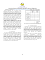
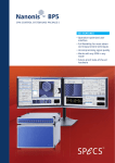
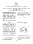
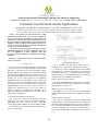
Fig 1: CAN Data Frame Types
I. INTRODUCTION
Fig. 1 (a) shows the data frame format, how it is
specified in the CAN protocol specification versions 1.0,
1.1, 1.2 and 2.0 A. Fully compatible to that is the standard
data format (Fig. 1 (b)), how it is specified in version 2.0 B.
In contrast to that Fig. 1 (c) describes the extended data
format with the 11+18=29 bit identifier (version 2.0 B).The
meaning of the three control bits is as follows:
The CAN is serial communication protocol that supports
real time systems with high reliability. It detects the
collisions; it also detects the errors, retransmits corrupt
messages and gives priority to the received and transmitted
messages. The identifier length can be either 11 bits or 29
bits and the data length can vary from 0 to 8bytes. The fast
growing use of the CAN protocol in the Industrial
applications resulted in development of the CAN based
network. In CAN based distributed control system, the
major problem is the size of distributed area. The physical
length limitation of the CAN bus is 2km at the rate of
20kbps. The maximum speed of the CAN protocol is
1mbps for 50metres and 500kbps for 100metres. Sleep
mode and wakeup are available options for each node to
reduce power consumption.
RTR bit - Remote Transmit Request
The RTR bit differentiates between data and remote
frames. In data frames this bit is dominant (’0’), in remote
frames this bit is recessive (’1’).
SRR bit - Substitute Remote Request
The SRR bit is a recessive bit. It is transmitted in
extended frames at the position of the RTR bit of standard
frames.
A. Standard and Extended Frame Format
Fig. 1 gives an overview of the different CAN data
frame types: All CAN messages start with the identifier
(arbitration) field. There are one or three control bits
coming along with the identifier. These bits define whether.
It is a standard or an extended frame and whether it is a
data or a remote frame.
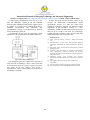
IDE bit - Identifier Extension
The IDE bit differentiates between standard and
extended frames. In standard frames this bit is dominant,
whereas in extended frames this bit is recessive. Similar to
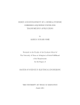
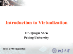
Fig. 1 showing the standard and extended frame formats of
CAN data messages, Fig. 2 shows the frame formats of
CAN remote messages. Here the RTR bit is set to recessive
(’1’).
370
International Journal of Emerging Technology and Advanced Engineering
Website: www.ijetae.com (ISSN 2250-2459, ISO 9001:2008 Certified Journal, Volume 4, Issue 3, March 2014)
C. The CAN error process
The error is detected by the CAN controller (a
transmitter or a receiver). An error frame is immediately
transmitted. The message is cancelled at all nodes
(exceptions exist - see CAN controller error modes). The
status of the CAN controllers is updated (see CAN
controller error modes). The message is re-transmitted. If
several controllers have messages to send, normal
arbitration is used.
i.
Error detection
Error detection is handled automatically by the CAN
controller. The detected errors are:
Bit errors:
1. Bit stuffing error: normally a transmitting node inserts a
high after five consecutive low bits(and a low after five
consecutive high). This is called bit stuffing. A receiving
node that detects violation (more than five consecutive bits
will see a bit stuffing violation.
2. Bit error: A transmitting node always reads back the
message as it is sending. If it detects a different bit value on
the bus than it sent, and the bit is not part of the arbitration
field or in the acknowledgement field and error is detected.
Fig. 2 CAN Remote Frame Types
In case that several nodes within one system start a
simultaneous transmission of message frames with the
same identifier, the following rules are valid: Data frames
have a higher priority than remote frames, and standard
frames have a higher priority than extended frames. That
means that e.g. a standard remote frame wins arbitration
against an extended data frame, if the 11 most significant
bits of the identifiers are equal.
Message errors:
1. Checksum error: each receiving node checks CAN
messages for checksum errors.
2. Frame error: There are certain predefined bit values that
must be transmitted at certain points within any CAN
Message Frame. If a receiver detects an invalid bit in one
of these positions a Form Error (sometimes also known as a
Format Error) will be flagged.
3. Acknowledgement Error: If a transmitter determines that
a message has not been acknowledged then an ACK Error
is flagged.
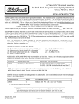
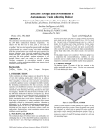
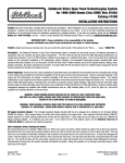
B. CAN and OSI Model
Many communication bus protocols do not use all the
seven layers of this OSI Model. Since CAN is a closed
network it doesn’t need to have security and to present the
data in a user interface. Also it does not need to maintain
sessions and logins. Hence it uses only two Layers such as
Physical and Data Link Layer. The CAN OSI model shown
in fig. 3 explains the transfer of data between two nodes.
ii.
Fig. 3 CAN and OSI model
The Physical Layer ensures the physical connection
between the nodes in the network. The Data Link layer
contains Frames and information to identify the frames and
errors. It has information also to determine the bus access.
371
CAN controller error modes
A CAN controller can be in one of three states:
1. Error active: the normal operating mode for a
controller. Messages can be received and transmitted. On
detecting an error an active error flag is sent (see error
signaling).
2. Error passive: a mode entered when the controller has
frequent problems transmitting or receiving messages.
Messages can be received and transmitted. On detecting an
error while receiving, a passive error flag is sent.
International Journal of Emerging Technology and Advanced Engineering
Website: www.ijetae.com (ISSN 2250-2459, ISO 9001:2008 Certified Journal, Volume 4, Issue 3, March 2014)
3. Bus off: entered if the controller has serious problems
with transmitting messages. No messages can be received
or transmitted until the CAN controller is reset by the host
microcontroller or processor.
The mode of the controller is controlled by two error
counters - the transmit error counter (tx_count) and the
receive error counter (rx_count). The following rules apply:
1. The CAN controller is in error active mode if tx_count
<= 127 AND rx_count <= 127.
2. Passive mode is used if (tx_count > 127 OR rx_count >
127) AND tx_count <= 255.
3. Bus off is entered if tx_count > 255.
Once the CAN controller has entered bus off state, it
must be reset by the host microcontroller or processor in
order to be able to continue operation. In addition, this is
only allowed after the reception of 128 occurrences of 11
consecutive recessive bits.
The counters are updated as follows:
1. When a receiver detects an error, the rx_count will be
increased by 1, except when the detected error was a bit
error during the sending of an active error flag or an
overload flag.
2. When a receiver detects a dominant bit as the first bit
after sending an error flag, the rx_count will be increased
by 8.
3. When a transmitter sends an error flag, the tx_count is
increased by 8.
Exception 1: If the transmitter is error passive and detects
an ack error because of not detecting a dominant ack and
does not detect a dominant bit while sending its passive
error flag.
Exception 2: If the transmitter sends an error flag because a
stuff error occurred during arbitration whereby the stuff bit
is located before the RTR bit, and should have been
recessive, and has been sent as recessive but monitored as
dominant.
4. If a transmitter detects a bit error while sending an active
error flag or an overload flag, the tx_count is increased
by 8.
5. If a receiver detects a bit error while sending an active
error flag or an overload flag the rx_count is increased
by 8.
6. Any node accepts up to 7 consecutive dominant bits after
sending an active or passive error flag or an overload flag.
After detecting the 14th consecutive dominant bit (in the
case of an active error flag or an overload flag), or after
detecting the 8th consecutive dominant bit following a
passive error flag, and after each sequence of additional 8
consecutive dominant bits every transmitter increases its
tx_count by 8 and every receiver increases its rx_count
by 8.
7. After the successful transmission of a message (getting
ack and no error until end of frame is finished) tx_count is
decreased by 1 unless it was already 0.
8. After the successful reception of a message (reception
without error up to the ack slot and the successful sending
of the ack bit), rx_count is decreased by 1 if it was between
1 and 127. If rx_count was 0 it stays 0, and if it was greater
than 127, it will be set to a value between 119 and 127.
Note: If a node is the only one on the bus (or during startup the only one that has become active), and it transmits a
message, it will get an acknowledgement error, and will
retransmit the message. This may lead to that node going to
error passive mode, but not to it becoming bus off (due to
exception 1 under point 3).
iii.
372
Error signaling
When an error is detected by a node it sends an error flag
on the bus. This prevents any other node from accepting the
message and ensures consistency of data throughout the
network.
The active error flag consists of six low bits, and is used
if the node transmitting the error frame is in active error
state. As low is dominant all other nodes will detect bit
stuffing violation and send their own error flags. After this,
nodes that want to transmit (including the one sending the
interrupted message) will start to do so. As usual, the node
whose message has the highest priority will win arbitration
and send its message.
If the CAN controller is in error passive mode the error
frame will consist of six passive (high) bits. Since the error
flag only consists of passive bits, the bus is not affected. If
no other node detected an error, the message will be sent
uninterrupted. This ensures that a node having problems
with receiving cannot block the bus.
All of this advanced error handling is done automatically
by the CAN controller, without any need for the host
microcontroller to do anything. This is one of the big
advantages of CAN.
International Journal of Emerging Technology and Advanced Engineering
Website: www.ijetae.com (ISSN 2250-2459, ISO 9001:2008 Certified Journal, Volume 4, Issue 3, March 2014)
iv.
Calculation of baud rate and sample point
Baud rate: The baudrate of the bus can be calculated from:
Baudrate = fcrystal / (2*n*(BRP+1))
Where n is the number of time quanta for one bit and is
defined as:
n = SYNCHSEG+TSEG1+TSEG2
BRP is the value of the BaudRate Prescaler. Warning:
some CAN controllers (like Intel 526) has another way of
calculating the number of time quantas in a bit! Consult
your user’s manual.
Sample point
Quantabeforesample = TSEG1 + 1
Quanta after sample = TSEG2
Often the sample point is given in percent of the bit time.
This is:
(TSEG1+1)/ (TSEG1+1+TSEG2)
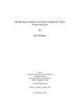
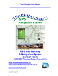
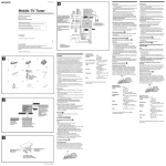
Fig. 4 CAN contain built in priority for messages to avoid conflicts.
E. Available Products
If standard frames are used exclusively in an application,
then both kinds of CAN controllers – those according to
version 2.0 B ("passive" or "active") as well as those
according to version 2.0 A (or even older versions) - can be
used. That means that for these CAN networks the full
range of available CAN controllers can be used. All future
CAN products will still perform standard frame
communication.
When extended frames are used in a CAN network, the
number of usable products is only an extract of the full
range of available CAN controllers. Because of the aim to
offer very cheap CAN controllers, it is likely that even
some future CAN controllers will be created which do not
support extended frame "actively". For most applications
the cheaper price will be more beneficial than the
additional feature of extended frame communication.
D. How CAN Communication Works
As stated earlier, CAN is a peer-to-peer network. This
means that there is no master that controls when individual
nodes have access to read and write data on the CAN bus.
When a CAN node is ready to transmit data, it checks to
see if the bus is busy and then simply writes a CAN frame
onto the network. The CAN frames that are transmitted do
not contain addresses of either the transmitting node or any
of the intended receiving node(s). Instead, an arbitration ID
that is unique throughout the network labels the frame. All
nodes on the CAN network receive the CAN frame, and,
depending on the arbitration ID of that transmitted frame,
each CAN node on the network decides whether to accept
the frame.
If multiple nodes try to transmit a message onto the
CAN bus at the same time, the node with the highest
priority (lowest arbitration ID) automatically gets bus
access. Lower-priority nodes must wait until the bus
becomes available before trying to transmit again. In this
way, you can implement CAN networks to ensure
deterministic communication among CAN nodes.
II. CAN APPLICATIONS
CAN was first created for automotive use, so its most
common application is in-vehicle electronic networking.
However, as other industries have realized the
dependability and advantages of CAN over the past 20
years, they have adopted the bus for a wide variety of
applications.
373
International Journal of Emerging Technology and Advanced Engineering
Website: www.ijetae.com (ISSN 2250-2459, ISO 9001:2008 Certified Journal, Volume 4, Issue 3, March 2014)
Railway applications such as streetcars, trams,
undergrounds, light railways, and long-distance trains
incorporate CAN. You can find CAN on different levels of
the multiple networks within these vehicles – for example,
in linking the door units or brake controllers, passenger
counting units, and more. CAN also have applications in
aircraft with flight-state sensors, navigation systems, and
research PCs in the cockpit. In addition, you can find CAN
buses in many aerospace applications, ranging from inflight data analysis to aircraft engine control systems such
as fuel systems, pumps, and linear actuators.
Medical equipment manufacturer’s use CAN as an
embedded network in medical devices. In fact, some
hospitals use CAN to manage complete operating rooms.
Hospitals control operating room components such as
lights, tables, cameras, X-ray machines, and patient beds
with CAN-based systems. Lifts and escalators use
embedded CAN networks, and hospitals use the CAN open
protocol to link lift devices, such as panels, controllers,
doors, and light barriers, to each other and control them.
CAN open also is used in nonindustrial applications such as
laboratory equipment, sports cameras, telescopes,
automatic doors, and even coffee machines.
Tab.1 Comparison of CAN Standard and Extended Frame Products
IV. FUTURE DEVELOPMENT
CAN Safety is a CAN-based technique providing safety
in field bus systems. It is not related to secure
communication where data encryption and decryption is
used to protect systems from unauthorized access. It
ensures the validity of CAN messages or the safety of the
hardware in relation to explosions. This technology already
exists, but is not commonly used in automotive
applications.
There are three types of CAN Safety technologies:
safety-related
communication,
safety-critical
communication and intrinsically safe communication. Here
there is a safe state the controller is forced into, given in
any failure for a safety-related communication. This type of
safety is found in CAN open Safety protocol and
DeviceNet CIP Safety protocol; however a custom safetyrelated communication can be design as well.
III. CONCLUSION
Tab. 1 tries a summarizing valuation of the standard and
extended frame formats regarding the number of different
identifiers, the bus access time, the bus throughput, the
CPU-load, the availability of products and the chip
size/cost. The result is, that it is advantageous to use the
standard frame format as long as the application allows to
do so. From today’s point of view only the American
automotive manufacturers have applications needing
extended frames. Therefore it should be recommended for
all other applications to use only standard frames.
374
International Journal of Emerging Technology and Advanced Engineering
Website: www.ijetae.com (ISSN 2250-2459, ISO 9001:2008 Certified Journal, Volume 4, Issue 3, March 2014)
A safety-critical communication does not use a safe
state, but redundancy instead. It can use redundant
networks and/or redundant communication. Figure 5 shows
an example of a safety-critical communication using a
redundant communication. The intrinsically safe
communication is simply a CAN physical layer rated for
certain conditions to ensure the
CAN hardware will not cause any explosions. It finds
applications in the petrochemical and chemical industries.
In 2010, this group released the latest version of the
protocol, the FlexRayTM Communications System
specifications Version 3.0.1. This new robust serial
networking technology designed for advanced control
applications in the automotive industry is a timedeterministic, scalable and fault-tolerant protocol having a
data rate up to 10 Mb/s. Like most new technologies
reaching the market, FlexRay is more expensive than older
similar technologies such as LIN and CAN.
REFERENCES
[1]
[2]
[3]
[4]
[5]
Fig. 5 Safety-critical communication.
[6]
Even though this paper has explained the superiority of
CAN over LIN, as technology evolves, a newer, faster and
even more robust protocol is going to replace CAN in the
near future. In the 21st century’s first decade, a
communication system called FlexRay was developed by
the FlexRay Consortium.
[7]
[8]
375
Bosch. “CAN Specification”, Version 2.0, Robert Bosch GmbH,
1991.
Kadionik, Patrice. “Le bus CAN”, École Nationale Supérieure
Électronique Informatique & Radiocommunications Bordeaux,
2001.
Held, Gilbert. “Inter- and intra-vehicle communications”, Auerbach
Publications, 2008.
Provencher, Hugo. “Introduction au protocole de communication
CAN” [Presentation], ELE4202 Commande des processus
industriels, Département degénie électrique, École Polytechnique de
Mtl, Automne 2009.
MotoHawk Training. “CAN (Controller Area Network)”
[Presentation], Woodward MotoTron Control Solutions, 28 October
2008.
http://progrm77.blogspot.com/2012/10/can-controller-areanetwork.html
http://wiki.altium.com/pages/viewpage.action?pageId=8753896
http://wenku.baidu.com/view/fff270bd960590c69ec376e5.html