1
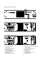
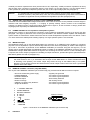
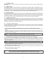
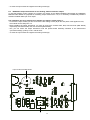
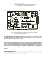
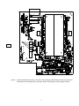
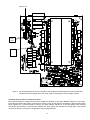
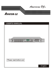
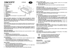
POWER AMPLIFIER DPA 4120 / DPA 4140
OWNER'S MANUAL
DPA 4140
40 0 WATT S POWER AMPL IF IER
CLIP
T EST
0dB
- 13dB
READY
STANDBY
GROUND
FAULT
PROT ECT
Performance Features
Power amplifier with 200 W or 400 W output power according to the IEC 283-3 standard within a
19“ - cabinet (3 HU) providing the following functions:
•
•
•
•
•
•
•
•
•
•
•
•
•
•
•
•
supported are 115/230V AC mains as well as 24V DC emergency power source
power amplifiers DPA 4120 providing 200 W or DPA 4140 providing 400 W output power, idling and short-circuit
protection
output transformer for balanced, floating 100 V speaker networks of optionally 70 V, 50 V or
4 ohms for low-impedance operation
optional input modules:
standard operation INPUT MODULE with level control, electronically balanced input and MONITOR output with
optional transformer or
REMOTE MODULE for controlling and monitoring the PROMATRIX system, electronic level controls, electronically
balanced input and MONITOR output with optional transformer
integrated stand-by power supply
mains POWER ON/OFF switch
ground lift switch
remotely controllable mains and battery operation with initial current inrush limiter
power-on switching noise suppression
status-LED indicators for operation (READY), STANDBY, thermal overload (PROTECT) and
occurrence of GROUND FAULT conditions at the power output
fault message according to the IEC 849 standard
TEST button to switch between system and average operation, respectively a RESET button to restart after the
occurrence of ground fault conditions
LED level meter instrument with a display range of -13 dB to 0 dB and CLIP
integrated relays for single call and obligatory reception
active, temperature controlled ventilation
pilot tone and ground fault surveillance module according to the DIN/VDE 0800 standard (optional)
23
24
Indicators, controls and connections
1 2
DPA 4140
4 0 0 WATT S PO WE R AM P L IFI ER
TES T
3
R EAD Y
STAN DBY
G RO UN D
FAUL T
4
PR OTE CT
C LIP
0dB
-1 3 d B
5
8
A
9
10
A
11
T4A FOR 230V
T8A FOR 115V
P OWER
12
7 6
13
A
B
NOUSER SERVICEABLE PARTS INSIDE. REFERSERVICING
TO QUALIFIED SERVICE PERSONNEL.
VOLTAGE
SELECTOR
115V
230V
DPA 4140
121629
AC MAI NS I NPUT
115V / 230V AC 50-60 Hz
INPUT
14
THRU
15
MADE IN GERMANY
CAUTION: FOR CONTINUED PROTECTION AGAINST RISK OF FIRE
REPLACE WITH SAME TYPE AND VALUE FUSE INDICAT ED.
ATTENTION: REMPLACER PAR UN FUSIBLE DE MEME TYPE
COMME INDIQUE.
B
C AUTION
A
ADDRESS
RISK OF ELECTRICSHOCK
DO NOT OPEN
3
2
1
OUT PUT
VO LTAG E
0
WARNING: TO REDUCE THE RISK OF FIRE ORELECTRIC SHOCK,
CIRCUIT T O
CHASSIS SWITCH
A
9
A
VO R ÖF F NEN DES G ER ÄTES NET Z ST ECKER Z IEHEN
19
10
T4A FOR 230V
T8A FOR 115V
1 2 3 4 5
18
11
POWER
16
POWER OUTPUT
GROUNDED
UNGROUNDED
20
10
REMOTE
CONTROL
AVIS: RISQUE DE CHOCELECTRIQUE. NE PAS OUVRIR.
+
7
8
9
LEVEL
DO NOT EXPOSE THIS APPLIANCE TO RAINOR MOISTURE.
DC I NPUT 24V
4 5 6
12
90225
17
B
15
A
VOLTAGE
SELECTOR
115V
230V
NO USER SERVICEABLE PARTS INSIDE. REFER SERVICING
TO QUALIFIED SERVICE PERSONNEL.
B
INPUT
DPA 4140
14
121629
AC MAINS INPUT
115V /230V AC 50-60 Hz
ADDRESS
M ADE IN GERMANY
A
CAUTION: FORCONTINUED PROT ECTIONAGAINST RISK OF FIRE
REPLACE WITHSAME TYPE AND VALUE F USE INDICATED.
ATTENTION: REMPLACERPARUN FUSIBLE DE MEME TYPE
COMME INDIQUE.
B
B
CA UTION
AD DRESS
RISK OF ELECTRIC SHOCK
DO NOT OPEN
THRU
IN
O UT PUT
VO LTAGE
WARNING: TO REDUCE THE RISK OF FIRE OR ELECTRICSHOCK,
REMOTE
CONTROL
DONOT EXPOSE THIS APPLIANCE TO RAIN ORMOISTURE.
22
AVIS: RISQUE DE CHOC ELECTRIQUE. NE PAS OUVRIR.
DC INPUT 24V
+
20
1
2
3
4
5
6
7
8
9
CIRCUIT TO
CHASSIS SWITCH
GROUNDED
UNGROUNDED
19
21
A
P OWER OUTPUT
OUT
23
STATUS
VO R Ö FF NEN DES G ERÄTES NET Z STECKER Z IEHEN
18
1 2 3 4 5
17
level meter instrument
CLIP indicator
Test and Reset button TEST
STANDBY indicator
Fault indicator PROTECT
Fault indicator GROUND FAULT
Mode indicator READY
Ventilation louvres
Mains power switch POWER
10
11
12
13
14
15
16
17
18
25
90222
B
Mains power connector AC MAINS INPUT
Mains fuse FUSE
Mains VOLTAGE SELECTOR
Input LEVEL control
INPUT socket
THRU socket
REMOTE CONTROL connector
POWER OUTPUT
Ventilation louvres
19
20
21
22
23
A
CIRCUIT ⊥ TO CHASSIS SWITCH
DC INPUT 24V = (battery)
IDENT ADDRESS switch
REMOTE CONTROL connectors
STATUS indicator
locking screws power supply printed board
B
locking screws INPUT MODULE
Contents
Performance Features......................................................................................................................... 23
Indicators, controls and connections .................................................................................................... 25
1.
Utilization ......................................................................................................................................... 27
2.
Installation ........................................................................................................................................ 27
3.
Before the first operation ..................................................................................................................... 27
3.1 Mains operation .......................................................................................................................... 27
3.2 Battery operation 24V DC ............................................................................................................. 28
4.
INPUT ............................................................................................................................................... 28
5.
Outputs ............................................................................................................................................. 29
5.1 POWER OUTPUT........................................................................................................................ 29
5.2 POWER OUTPUT for 100V (70V or 50V) loudspeaker systems........................................................ 29
5.3 SINGLE CALL and obligatory reception relays OVERRIDE BYPASS................................................ 29
5.4 POWER OUTPUT for low impedance loudspeaker systems............................................................. 29
5.5 MONITOR output ......................................................................................................................... 30
5.6 REMOTE CONTROL connector (only NRS 90225) .......................................................................... 30
6.
Indicators .......................................................................................................................................... 30
6.1 STANDBY indicator...................................................................................................................... 30
6.2 READY indicator.......................................................................................................................... 30
6.3 PROTECT indicator...................................................................................................................... 30
6.4 GROUND FAULT indicator............................................................................................................ 30
6.5 Aussteuerungskontrolle und CLIP-Anzeige ..................................................................................... 31
7.
Switching the output voltage ................................................................................................................ 31
8.
Enhanced application field................................................................................................................... 32
8.1 General input module NRS 90225.................................................................................................. 32
8.2 Remote module NRS 90222.......................................................................................................... 32
8.3 NRS 90208 input transformer for the floating, balanced input ............................................................ 33
8.4 NRS 90227 output transformer for the floating, balanced monitor output ............................................ 33
8.5 NRS 90224 pilot tone and ground fault surveillance.......................................................................... 35
8.5.1 Pilot tone surveillance.......................................................................................................... 35
8.5.2 Ground fault surveillance...................................................................................................... 35
9.
19"-case and 19“-rack shelf system installation..................................................................................... 38
10.
Ground lift switch CIRCUIT ⊥ TO CHASSIS SWITCH.............................................................................. 38
11.
Fuses................................................................................................................................................ 38
11.1 Fuses in the DPA....................................................................................................................... 38
11.2 Fuses in the DPA....................................................................................................................... 38
12.
Power amplifier specifications .............................................................................................................. 42
12.1 DPA 4120 power amplifier 200 W................................................................................................. 42
12.2 DPA 4140 power amplifier 400 W................................................................................................. 43
13.
Extension specifications ..................................................................................................................... 44
13.1 NRS 90225 general input module................................................................................................. 44
13.2 NRS 90222 remote module ......................................................................................................... 44
13.3 NRS 90208 input transformer for floating, balanced input ................................................................ 44
13.4 NRS 90227 output transformer for floating, balanced monitor output ................................................ 44
13.5 NRS 90224 pilot tone and ground fault surveillance........................................................................ 44
14.
Block diagrams .................................................................................................................................. 67
14.1 Power amplifiers DPA 4120 / DPA 4140 ........................................................................................ 67
14.2 NRS 90225 general input module................................................................................................. 68
26
15.
14.3 NRS 90222 remote module ......................................................................................................... 69
14.4 NRS 90224 pilot tone and ground fault surveillance........................................................................ 70
Warranty ........................................................................................................................................... 72
1.
Utilization
The amplifiers DPA 4120 and DPA 4140 are specially designed for the power-consistent and reliable operation of PAsystems. The DPA 4120 and DPA 4140 are intended to be used in company intercom, alarm and background music
transmission installations, offices and commercial areas, congregation and sport centers, schools, churches, hotels,
hospitals, shopping malls and super markets, cruise ships, and other similar applications.
2.
Installation
When installing the amplifiers, it is important to assure that for ventilation reasons the front-to-rear air circulation is
guaranteed (for details on 19"-case or 19“-rack shelf installation please refer to paragraph 9).
To maintain EMC it is necessary that all input, output, and control lines – except for the power cords – are shielded.
Within metal housings or closed rack shelf systems, unshielded output and control cabling is allowable. Shielding is
accomplished by connecting the individual cable screens to the enclosure or rack shelf ground potential.
The amplifier has to be protected from:
- water drops or splashes
- direct sunlight
- high ambient temperatures and the direct radiation of heat sources
- high humidity and moisture
- heavy dust
- massive vibrations
Moving the amplifier from a cold into a warm environment can result in the occurrence of condensation on inner parts.
Operating the appliance is only permissible after it has accommodated to the altered temperature (approximately after
one hour).
Should it happen that foreign solid parts or liquids inadvertently intrude the enclosure, unplug the device from the
power source and have it checked by a DYNACORD service center, before using it again.
Cleaning the appliance should not be performed using chemical solvents or sprays, as this might damage the finish
and moreover could cause hazard fire.
3.
Before the first operation
These power amplifiers are designed to be operated with different input modules. The general input module NRS
90225 is meant for all conventional applications. It allows to remotely start the amplifiers via control lines, monitor their
operation by use of the incorporated fault relay, and monitor the transmitted audio signals through the monitor output.
Using the remote control module NRS 90222, the amplifiers are connected to the PROMATRIX manager DPM 4000
via RS-485 remote interface providing complete remote operation and surveillance. The desired input module has to be
inserted into the module shaft on the rear of the power amplifier. It has to be tightened using the two locking screws
(B) (refer also to the paragraphs 8.1 and 8.2).
3.1 Mains operation
For normal AC mains operation, the included mains cord has to be connected to a 230V or 115V 50/60Hz wall outlet.
On the appliance itself, the cord has to be connected to the 3-pole mains socket (10).
Caution
The appliance is factory preset to 230V AC. Switching to 115V AC is accomplished using the voltage
selector (12).
27
DPA 4120: For 115V AC operation, the mains fuse (11) has to be replaced by a slow blowing
4 ampere type, labeled "T4A" (see also paragraph 11.1).
DPA 4140: For 115V AC operation, the mains fuse (11) has to be replaced by a slow blowing
8 ampere type, labeled "T8A" (see also paragraph 11.2).
If the appliance is correctly connected and mains is present the green STANDBY indicator (4) will light. To remotely
start the amplifier when it is being operated on the mains, it is necessary to interconnect the contacts 3 - POWER
REMOTE and 2 - GROUND STANDBY on the pin terminal strip REMOTE CONTROL (16) (see also paragraph 5.6).
The main power switch POWER (9) on the rear of the appliance is meant for service and maintenance purposes. This
allows bridging the mains switching relay, which provides the possibility to operate the amplifier without remote start.
Note
The main power switch POWER (9) on the appliance's rear is only meant for maintenance. Remotely
switching off the device is not possible when the POWER switch is engaged.
Both amplifiers, the DPA 4120 and the DPA 4140, employ power-on switching delays of approximately 3 sec. After
this time, the green READY indicator lights and the READY fault message relay picks up when no error is being
detected (see also paragraph 6.2).
3.2 Battery operation 24V DC
The amplifiers, DPA 4120 and DPA 4140, use the mains or alternatively an external 24V battery as power source.
Switching to battery is performed via integrated relays.
The battery has to be connected on the rear of the amplifiers (20) using insulated 6.3x0.8 mm AMP flat plug
connectors. The amplifiers are protected against polarity-mismatch. Each, the positive and negative conductors are
internally protected by fuses, located on the printed board assembly 85270 (DPA 4120) respectively 85268 (DPA
4140) (see also paragraph 11, figure 10 and 11).
The cable used for battery connection has to be at least 1.5 mm2 in diameter (DPA 4120) respectively 2.5 mm2 (DPA
4140). Using these diameters, the cable length for the one way distance should not exceed 4.0 m (max. voltage drop
<1V).
Caution
The DPA 4120 and DPA 4140 are to be operated only using ungrounded batteries or batteries with
grounded negative pole. Operation with grounded positive pole is not permissible.
4.
INPUT
The electronically balanced INPUT (14) providing a sensitivity of 775mV = 0dBu is meant for the connection of control
amplifiers. In case it is intended to supply several power amplifiers with identical input signals, these signals can be
taken from the THRU connector (15) (see also figure 1 and 2).
The input is prepared to be retrofitted with a input transformer. In case a floating input is needed, it is necessary to
install the optional extension NRS 90208 (see also paragraph 8.3).
On the general input module NRS 90225 the input level is set with the level control (13). For the remote control
module NRS 90222 the input level is determined by the setting of the internal electronic level control of the
PROMATRIX manager DPM 4000 (please also refer to the PROMATRIX handbook).
28
figure 1 connections of the input sockets
figure 2 LF cable for coupling two amplifiers DPA 41xx
5.
Outputs
5.1 POWER OUTPUT
The power output is balanced and off-ground potential. The output is factory-configured for the connection of 100V
loudspeaker systems. Connection has to be performed by inserting the supplied 5-pole plug into the power output
socket (17). Switching the output voltage to 70V, 50V or to low impedance operation (4 ohms) is possible using the
plug-in bridge B411 on the printed board assembly 84187 (DPA 4120) respectively 84175 (DPA 4140) (see also
paragraph 7).
figure 3 connection of the power output
5.2 POWER OUTPUT for 100V (70V or 50V) loudspeaker systems
If the distance between the amplifier and the loudspeakers exceeds 50 m, it is recommended to operate the speaker
systems using 100V matching transformers, to reduce line attenuation. This additionally offers a simple way of
distributing the output power capacity. In this way it is possible to connect a maximum of as many loudspeaker
systems as it takes until the total power consumption of the entire speaker network equals the power output capacity
29
of 200W (connection impedance 50 ohms) with the DPA 4120, respectively 400W (connection impedance 25 ohms)
with the DPA 4140. Connection is performed using the 100V output (17) (see also figure 3). In a few special cases it
is also possible to operate the loudspeaker systems with 70V or 50V output voltage (see also paragraph 7).
Caution
It is possible that during operation shock-hazard output voltages can be present at the POWER
OUTPUT connector (>34V peak value). Thus, the connected loudspeaker groups have to be installed in
accordance to applicable security standards and regulations (see also paragraph 8.5.2).
5.3 SINGLE CALL and obligatory reception relays OVERRIDE BYPASS
Combined with the PROMATRIX manager DPM 4000 or other external controls it is also possible to transmit single or
collective calls with obligatory reception; i. e. bridging of possibly existing volume controls of the loudspeaker
systems. For details on how to connect the outputs, please refer to figure 3; for the connection of relays, please refer
to paragraph 5.6 respectively the PROMATRIX handbook.
5.4 POWER OUTPUT for low impedance loudspeaker systems
Switching the output to 4 ohms allows the connection of low impedance loudspeaker systems (4-16 ohms) (see also
paragraph 7 and figure 3). Because of the occurring line attenuation, the distance between amplifier and loudspeaker
system should not exceed 50m. Please make sure that the overall loudspeaker impedance does not decline a value
of 4 ohms and that the stated power handling capacity of a single speaker system is not exceeded.
5.5 MONITOR output
The MONITOR output (16) on the NRS 90225 allows the connection of an additional power amplifier for monitoring
purposes. The low impedance output is electronically balanced, which offers the possibility to achieve cable lengths of
up to 200 m. Connection is performed via the REMOTE CONTROL pin-connector strip (see also figure 4). For the
remote control module NRS 90222, the MONITOR output is located on the REMOTE CONTROL connector (22). The
PROMATRIX manager DPM 4000 switches the signal to the according the monitor channel. In case a floating output
is required, the monitor output is prepared for retrofitting an output transformer; provided through the optional extension
NRS 90227 (please also refer to paragraph 8.4).
Note:
Functioning changes in the models DPA 4120 (starting with serial numbers: 100 11) and DPA 4140 (starting
with serial numbers: 100 11) in association with the input module NRS 90225: To achieve reliable attenuation
of switching noise (knacks), the monitor output stays muted as long as the READY-relay is not pulled.
Because of circuit design reasons this causes that the monitor output is also muted even when a ground-fault
appears at the main output.
5.6 REMOTE CONTROL connector (only NRS 90225)
The 15-pole sub-D REMOTE CONTROL pin-connector strip (16) provides several different control in-/outputs:
- Ground of the stand-by power supply
- POWER REMOTE
- BATTERY REMOTE
- MONITOR output
- READY-message
- Obligatory reception relay D-RELAY
- Single call E-RELAY
2
3
4
5
6
7
8
15
9
10
- negative pole grounded
- via contact to ground potential
- via contact to ground potential
- electronically balanced
- with floating contact
- via contact to ground potential
- via contact to ground potential
⊥ STANDBY GROUND
POWER REMOTE
BATTERY REMOTE
D - RELAY
E - RELAY
REMOTE CONTROL
READY
+ MONITOR
- MONITOR
figure 4 connections on the REMOTE CONTROL pin-connector strip
6.
Indicators
30
6.1 STANDBY indicator
When the appliance is correctly connected and mains and/or battery power is present, the green STANDBY indicator
(4) will light.
6.2 READY indicator
Both amplifiers, the DPA 4120 and the DPA 4140, employ power-on switching delays of approximately 3 sec. to
effectively eliminate power-on switching noise. After this time, the green READY indicator (7) lights and the READY
fault message relay picks up when no error is being detected. When the power amplifier's mains transformer exceeds
a certain value or, when – with installed NRS 90224 extension – the pilot tone falls below the threshold (see also
paragraph 8.5.1), the green READY indicator (7) is not lit and the READY fault message relay drops.
6.3 PROTECT indicator
When thermal overload of the mains transformer or the power amplification stage is encountered, the red PROTECT
indicator (5) will light and the READY fault message relay drops. After the amplifier regained normal temperature, the
red PROTECT indicator (5) is automatically dimmed and the appliance returns to normal operation. High temperature
can be caused by overload, extreme ambient temperatures or faulty functioning of the system's ventilation.
6.4 GROUND FAULT indicator
If, with the NRS 90224 extension installed, a ground fault is being detected at the power output, the red GROUND
FAULT indicator (6) will light and the READY fault message relay will drop. During the occurrence of this error normal
operation is maintained. After eliminating the cause for the ground fault, pressing the TEST button (3) resets the
GROUND FAULT indicator (6) (see also paragraph 8.5.2).
6.5 Level meter and CLIP indicator
The green LED-indicators -13dB and 0dB (1) together with the red CLIP-LED (2) allow to monitor the output level,
effectively avoiding overdrive conditions that lead to distortion and overload at the power outputs which could damage
the connected loudspeaker systems.
- If the red CLIP-LED (2) shortly lights during program peaks, maximum non-distorted modulation is achieved.
- Continuous lighting or blinking of the red CLIP-LED (2) signals overdrive. In this case the input level has to be
reduced.
- If the green LED indicator (1) does not light or is only briefly lit with the red CLIP-LED blinking at the same time, this
signals the encountering of an overload or short-circuit condition at the output. In this case the impedance of the
connected load has to be checked.
Caution
During normal operation the red CLIP-LED should only light briefly and shortly!
7.
Switching the output voltage (only to be performed by a qualified service technician!)
The DPA 4120 and DPA 4140 amplifiers allow the connection of 50V, 70V, 100V or low-impedance loudspeaker
systems (4 ohms). They are factory-preset to an output voltage of 100 V. Switching the output voltage to 4 ohms, 50V
or 70V can be performed by changing the bridge B411 on the power amplifier printed board assembly 84187 (DPA
4120) or 84175 (DPA 4140):
Caution
Before opening the appliance, make sure to disconnect the mains and/or battery power source!
- To open the appliance, the top panel has to be removed.
- The bridge B411 (yellow wire) has to be removed from the contact B407 and re-attached to the desired contact (see
table 1) (see also figure 8 respectively figure 9).
- he coding-bridges S405 and S406 for the output recognition have to be inserted according to the illustration in figure
5.
(the inserted coding-bridge is marked in black)
The top panel has to be re-attached.
Note
By using a waterproof marker pen and after switching the output voltage, the newly set value
has to be marked in the filed "OUTPUT VOLTAGE" on the rear panel of the appliance.
31
output
100 V
70 V
50 V
4 ohms
bridge
B411 to
B407
B408
B409
B410
table 1 bridge B411 settings
switching the output voltage
Caution
figure 5 coding-bridges S405 / S406 settings
output recognition OUTPUT CONFIG
It is possible that during operation shock-hazard output voltages can be present at the POWER
OUTPUT connector (>34V peak value). Thus, the connected loudspeakers have to be installed in
accordance to applicable security standards and regulations (see also paragraph 8.5.2).
8.
Enhanced application field
8.1 Standard input module NRS 90225
This input module for the power amplifiers DPA 4120 and DPA 4140 is meant for insertion at the power amplifiers'
rear. It provides the following functions:
•
•
•
•
•
•
•
•
•
•
lockable XLR input connector
XLR output connector; to patch the input signal through
gain control; to be adjusted using a screwdriver
mains remote ON/OFF
battery remote ON/OFF
control of the D- and E-relays
fault messages via the READY relay contact:
- thermal overload of the mains transformer
- thermal overload of the power amplification stage
- ground fault (optional; only with installed NRS 90224)
- pilot tone signal (optional; only with installed NRS 90224)
MONITOR output; electronically balanced
input transformer for floating, balanced input; optional
output transformer for floating, balanced monitor output; optional
The input module is meant to be used with the power amplifiers DPA 4120 and DPA 4140. The module allows to
control and monitor the operation of the power amplifiers using conventional equipment or (with reservations) by the
PROMATRIX manager DPM 4000.
Caution:
Before installing the input module NRS 90225, you have to unplug the mains connector as well as a
presumably connected battery cord.
Before installing the input module, it is necessary to remove the two locking screws B on the rear panel of the
appliance. For installation the printed board assembly first has to be inserted into the guiding rails. After carefully
pushing the module in it has to be locked by using the two screws mentioned before.
32
Note:
Functioning changes in the models DPA 4120 (starting with serial numbers: 100 11) and DPA 4140 (starting
with serial numbers: 100 11) in association with the input module NRS 90225: To achieve reliable attenuation
of switching noise (knacks), the monitor output stays muted as long as the READY-relay is not pulled.
Because of circuit design reasons this causes that the monitor output is also muted even when a ground-fault
appears at the main output.
8.2 Remote module NRS 90222
This input and remote module for the power amplifiers DPA 4120 and DPA 4140 is meant for insertion at the power
amplifiers' rear. It provides the following functions:
•
•
•
•
•
•
•
•
•
•
•
•
•
lockable XLR input connector
XLR output connector; to patch the input signal through
input level; can be set via a programmable audio level control
MUTE (via level control)
mains remote ON/OFF
battery remote ON/OFF
control of the D- and E-relays
surveillance and fault messaging via the PROMATRIX manager DPM 4000 corresponding to IEC 849
- thermal overload of the mains transformer
- thermal overload of the power amplification stage
- ground fault (optional; only with installed NRS 90224)
- pilot tone signal (optional; only with installed NRS 90224)
- measurement of the output voltage / level
- measurement of the output current
- surveillance of the connected loads via current/voltage measurement
MONITOR output; electronically balanced
monitoring: input/output signals can be assigned to the monitor bus
input transformer for floating, balanced input (optional)
output transformer for floating, balanced monitor output (optional)
pilot tone signal ON/OFF (optional)
The remote module allows to remotely control and monitor the operation of the power amplifiers DPA 4120 and DPA
4140 from the PROMATRIX manager DPM 4000 (for further details please refer to the PROMATRIX handbook).
Caution:
Before installing the input module NRS 90222, you have to unplug the mains connector as well as a
presumably connected battery cord.
Before installing the input module, it is necessary to remove the two locking screws B on the rear panel of the
appliance. For installation the printed board assembly first has to be inserted into the guiding rails. After carefully
pushing the module in it has to be locked by using the two screws mentioned before.
Note
After installing the remote module NRS 90222 it is necessary to set its address according to the
description in the PROMATRIX handbook using the two "HEX-code switches" ADDRESS (21) and note
the setting within the field ADDRESS on the rear panel of the appliance using a waterproof marker pen.
8.3 NRS 90208 input transformer for the floating, balanced input
For the case that floating inputs are required, the inputs of the INPUT MODULE NRS 90225 and the REMOTE
MODULE NRS 90222 are prepared for retrofitting input transformers. If so, it is necessary to additionally install the
extension kit NRS 90208 per each input.
The installation has to be performed as follows (see figure 6 and/or figure 7):
- to remove the input module you have to loosen the two locking screws (B) on the rear panel of the appliance. Now,
the module can be easily torn out.
- before installing the input transformer you have to remove the resistors R1 and R2.
- mount the input transformer onto the printed board assembly, so that the marking located on the connector side of
the transformer matches with the one on the printed board assembly. To prevent short-circuits place the supplied
insulation disc between the transformer and the printed board assembly.
33
- re-insert the input module and tighten the locking screws (B).
8.4 NRS 90227 output transformer for the floating, balanced monitor output
In case that floating monitor outputs are required, the outputs of the INPUT MODULE NRS 90225 and REMOTE
MODULE NRS 90222 are prepared for retrofitting output transformers. If so, it is necessary to additionally install the
extension kit NRS 90227 per each output.
The installation has to be performed as follows (see figure 6 and/or figure 7):
- to remove the input module you have to loosen the two locking screws (B) on the rear panel of the appliance. Now,
the module can be easily torn out.
- before installing the output transformer you have to remove the resistors R22, R23, R32 and R33 (NRS 90225)
respectively the resistors R23, R24, R71 and R72 (NRS 90222).
- now, you can mount the output transformer onto the printed board assembly. Because of the transformer's
symmetrical design, polarity is not a critical factor.
- re-insert the input module and tighten the locking screws (B).
Input Transformer NRS 90208
34
Output Transformer NRS 90227
figure 6 printed board assembly 81338 showing the input transformer
NRS 90208 and the output transformer NRS 90 227
Input Transformer NRS 90208
Output Transformer 90 227
figure 7 printed board assembly 81339 showing the input transformer NRS 90208
and the output transformer NRS 90 227
8.5 NRS 90224 pilot tone & ground fault surveillance
The extension NRS 90224 is meant for insertion. It includes a 19 kHz tone generator and a selective 19 kHz receiver
with evaluation stage for pilot tone surveillance. Also incorporated is a monitoring circuit with fault storage and display
driver, to guard the cable network connected to the output.
8.5.1 Pilot tone surveillance:
Integration of the extension NRS 90224 provides continuous self-monitoring of the amplifier. This gets accomplished in
the way that an extremely low-level 19 kHz pilot tone signal is introduced to the signal path following the input level
control LEVEL. After passing the amplifier stages, the pilot tone signal is filtered out at the output and the result is
evaluated. If the measured signal declines the pilot tone's predetermined threshold at the output or is not present at
all, the READY indicator (7) dims and the READY fault message relay drops. When using the INPUT MODULE NRS
90225, the fault message is output as collective fault message with the floating contact of the READY fault message
relay via the REMOTE CONTROL connector (16). When using the REMOTE MODULE NRS 90222, error occurrence
is monitored and output by the PROMATRIX manager DPM 4000 (for further details, please refer to the PROMATRIX
handbook).
8.5.2 Ground fault surveillance:
When installing and operating 100V-loudspeaker networks, compliance to the VDE regulation DIN VDE 0800 is
mandatory. Especially, if 100V-loudspeaker networks are included in alarm system applications, all security
standards have to be in accordance to the security class 3 standard.
35
When off-ground potential loudspeaker cable networks are employed we recommend insulation-monitoring using the
ground fault surveillance module NRS 90224. Error recognition: An occurring ground fault either signals that one of the
cables is damaged - which most likely point towards a total line interruption in the near future - or that connections
have been carried out erroneously which may lead to malfunctioning of the entire system. The fault message
GROUND FAULT (6) is also maintained with very short (>5 sec) ground faults, as long as the amplifier is powered-on
or a loaded battery is connected. The fault message is displayed via the red GROUND FAULT indicator (6). In case of
an inserted INPUT MODULE NRS 90225, it is also outputted as collective fault message with the floating contact of
the READY fault message relay via the REMOTE CONTROL connector (16). When using the REMOTE MODULE
NRS 90222, error occurrence is monitored and output by the PROMATRIX manager DPM 4000 (for further details,
please refer to the PROMATRIX handbook).
The installation has to be performed as follows (see figure 8 and/or figure 9):
Caution
Before opening the appliance, make sure to disconnect the mains and/or battery power source!
- To open the appliance, the top panel has to be removed.
- The extension kit NRS 90224 has to be inserted with its component side to the left (from the front view) until it clicks
in place.
- Re-install the top plate of the enclosure.
NRS 90 224
S 406
S 405
36
B 411
figure 8
printed board assembly 84187 in the DPA 4120 showing the NRS 90224 pilot tone & ground fault
surveillance and the bridges B411 and S405, S406 for switching the output voltage; inserted
37
NRS 90 224
S 406
S 405
B 411
figure 9
printed board assembly 84175 in the DPA 4140 showing the NRS 90224 pilot tone & ground fault
surveillance and the bridges B411 and S405, S406 for switching the output voltage; inserted
Checking the pilot tone surveillance function:
When the NRS 90224 is installed and the power amplifier is switched on, the green READY indicator (7) has to light.
The testing and reset button TEST (3) serves as a function control for the pilot tone surveillance. With the TEST button
being engaged, the 19 kHz generator is inactive. The green READY indicator is off and the READY fault message
relay drops. Approximately 3 seconds after releasing the TEST button, the indicator has to light again. This method
can also be used to check system configurations with average-switching.
38
Checking the ground fault surveillance function:
When the NRS 90224 is installed and the power amplifier is switched on, the green READY indicator (7) has to light.
Utilizing an external switch to connect one pole of the 100V-loudspeaker network via a 47 k ohms resistor for
approximately 5 seconds to ground potential, the corresponding red GROUND FAULT indicator (6) has to light and the
READY fault message relay of the INPUT MODULE NRS 90225 drops while the green READY indicator (7) stays lit.
After releasing the button, the indication and the fault message are maintained. The TEST button (3) has to be used to
reset the ground fault surveillance function. For further details on checking the function with the REMOTE MODULE
NRS 90222 being included in your installation, please refer to the PROMATRIX handbook.
9.
19"-case and 19“-rack-shelf system installation
Note
Operation of the power amplifiers DPA 4120 and DPA 4140 with enclosure cover plates detached is
strictly prohibited.
When mounting the power amplifiers within rack-cases or rack-shelf systems make sure to provide sufficient airflow.
The space between the rear panel of the amplifier and the inner wall of the rack-case has to be at least 60 mm x 330
mm. A free space of at least 100 mm above the rack-shelf system is needed to provide sufficient air circulation. Since
it is possible that during operation the temperature inside the rack system increases by 10° C, the maximum
allowable ambient temperatures of the rest of the incorporated modules and appliances within a specific rack-shelf or
rack-case have to be taken into careful consideration.
Note
To ensure trouble-free operation of the appliance, the maximum permissible ambient temperature of
+40°C is not to be exceeded.
10. Ground lift switch CIRCUIT ⊥ TO CHASSIS SWITCH
The ground lift switch CIRCUIT ⊥ TO CHASSIS SWITCH (19) provides the possibility to separate the signal ground
from the enclosure (ground potential). This is mainly meant to eliminate noise-problems which are introduced through
ground-loops, without jeopardizing the security. In case several appliances within a single rack-case or rack-shelf are
furnished with ground lift switches, it is recommended to set all devices but one to "ungrounded“. Set one appliance to
"grounded". When set to "ungrounded", the impedance between signal ground and enclosure is : 100 k ohms // 100
nF. It is needed to maintain EMV protection.
11.
Fuses
11.1 Fuses in the DPA 4120
location
Pos.
fuse socket (11)
F601
fuse socket (11)
F601
printed board assembly F602
86243
printed board assembly F502
85270
printed board assembly F503
85270
11.2 Fuses in the DPA 4140
location
Pos.
fuse socket (11)
F601
fuse socket (11)
F601
printed board assembly F602
86243
printed board assembly F502
85268
printed board assembly F503
85268
purpose
mains fuse 230V~ AC
mains fuse 115V~ AC
mains fuse 100V - 250V
value
T2A
T4A
T1A
dimensions
5x20 mm
5x20 mm
Ø 8.5xRM 5.08mm
standard
IEC 127-2-3
IEC 127-2-3
IEC 127-3/4
battery fuse 24V DC
15A
flat fuse
DIN 72581-3
battery fuse 24V DC
15A
flat fuse
DIN 72581-3
purpose
mains fuse 230V~ AC
mains fuse 115V~ AC
mains fuse 100V - 250V
value
T4A
T8A
T1A
dimensions
5x20 mm
5x20 mm
Ø 8.5xRM 5.08mm
standard
IEC 127-2-3
IEC 127-2-3
IEC 127-3/4
battery fuse 24V DC
25A
flat fuse
DIN 72581-3
battery fuse 24V DC
25A
flat fuse
DIN 72581-3
39
F 503 F 502
figure 10 printed board assembly 85270 in the DPA 4120 showing the DC fuses F502 and F503
40
F 503 F 502
figure 11 printed board assembly 85268 in the DPA 4140 showing the DC fuses F502 and F503
41
F 601
F 602
figure 12 printed board assemblies 86243 DPA 4120 and DPA 4140 showing the AC fuses F601 and F602
Caution
Before opening the appliance, make sure to disconnect the mains and/or battery power source!
Replacing the fuses F502 and F503 (only to be carried out by the experienced service technician!)
The battery fuses F502 and F503 are located on the power supply PCBs 85270 (DPA 4120) and 85268 (DPA 4140)
behind the AMP battery connectors (see also figure 10 and/or figure 11). To replace these fuses you have to remove
the cover plate of the appliance and afterwards the power supply input PCB 86243 which is mounted to the rear panel
of the appliance. Therefore detach the yellow/green cable from the ground-connector on the appliance's rear panel.
Pressing the lock-strap of the AMP-connector together, it can be removed without applying any force. Now, you have
to remove the three screws marked "A" (refer to the diagram of the appliance's rear panel on page 2) which allows you
to twist the power supply input PCB 86243 up. Make sure not to damage any wires or any other parts. The fuses
F502 and F503 are now accessible and can be removed. To re-install the power supply input PCB 86243, these steps
have to be proceeded in the opposite order. The yellow/green cable has to be reconnected to the ground-connector on
the rear panel of the appliance. By pulling the cable make sure that it sits snugly. Then you can re-attach the cover
plate of the enclosure.
42
Caution
12.
For security reasons it is necessary to ensure that, after the installation is completed, all wiring located
beneath the power supply input PCB are within a distance of at least 6 mm to the printed board
assembly.
Specifications
12.1
DPA 4120 power amplifier 200 W
power supply:
mains operation
mains frequency
security class
mains operation
idling
normal operation (-10 dB)
alarm (-3 dB)
standard conditions
initial current inrush (mains)
mains operation
idling
normal operation (-10 dB)
alarm (-3 dB)
standard conditions
initial current inrush (mains)
115 V / 230 V~ AC, ±10 %
50 - 60 Hz
I
Umains / V Imains / A Pmains / VA
230
230
230
230
0.13
0.83
1.67
2.27
< 29 A
Pout / W
Pv / W
16
138
298
415
0
20
100
200
16
118
198
215
Pmains / W
Pout / W
Pv / W
16
138
298
415
0
20
100
200
16
118
198
215
30
191
384
522
Umains / V Imains / A Pmains / VA
115
115
115
115
Pmains / W
0.26
1.67
3.34
4.54
< 20 A
30
191
384
522
Pmains / VA = apparent power Umains*Imains ; Pmains / W = true power; Pout / W = output power; Pv / W =leakage power
battery operation
battery operation
stand-by
idling
normal operation (-10 dB)
standard conditions
initial current inrush (battery)
24 V DC, -10/+30 %
UB / V
IB / A
Pi / W
Pout / W
Pv / W
24
24
24
24
2.5m
0.43
3.74
9.10
< 3.8 A
60m
10
90
218
0
0
20
131
60m
10
90
87
Pi / W = input power UB*IB; Pout / W = output power; Pv / W = leakage power
features of the input:
nominal input level
nominal input impedance
features of the power output:
nominal output capacity during mains operation
nominal load impedance
electronically balanced
775 mV = 0 dBu
≥ 10 k ohms
balanced, floating
200 W (according to IEC 268-3)
50 ohms / 100V; 25 ohms / 70 V; 12.5 ohms / 50 V
or 4 ohms / 28 V
60 Hz .. 20 kHz
≤ 1%
≤ 1.2 mV = -56 dBu
electronically balanced
2 V = + 8.2 dBu
600 ohms
frequency response
distortion at 1 kHz and nominal output power
interfering voltage (A)
features of the monitor output:
nominal output voltage
nominal load impedance
43
ambient temperature range
dimensions (W x H x D)
depth with / without connections
weight without extensions
finish
+5 °C .. +40 °C
483 x 132 x 345 mm
max. 400 mm / max. 340 mm
13.2 kg
anthracite
12.2 DPA 4140 power amplifier 400 W
power supply:
mains operation
mains frequency
security class
115 V / 230 V~ AC, ±10 %
50 - 60 Hz
I
mains operation
idling
normal operation (-10 dB)
alarm (-3 dB)
standard conditions
initial current inrush (mains)
mains operation
idling
normal operation (-10 dB)
alarm (-3 dB)
standard conditions
initial current inrush (mains)
Umains / V Imains / A Pmains / VA
230
230
230
230
0.19
1.60
3.10
4.43
< 36 A
Pout / W
Pv / W
23
263
562
811
0
40
200
400
23
223
362
411
Pmains / W
Pout / W
Pv / W
23
263
562
811
0
40
200
400
23
223
362
411
44
368
713
1019
Umains / V Imains / A Pmains / VA
115
115
115
115
Pmains / W
0.38
3.19
6.20
8.86
< 21 A
44
368
713
1019
Pmains / VA = apparent power Umains*Imains ; Pmains / W = true power; Pout / W = output power; Pv / W =leakage power
battery operation
battery operation
stand-by
idling
normal operation (-10 dB)
standard conditions
initial current inrush (battery)
24 V DC, -10/+30 %
UB / V
24
24
24
24
IB / A
Pi / W
Pout / W
2.5m
0.62
7.1
17.3
< 3.8 A
60m
15
170
415
0
0
40
249
Pv / W
60m
15
130
166
Pi / W = input power UB*IB; Pout / W = output power; Pv / W = leakage power
features of the input:
nominal input level
nominal input impedance
features of the power output:
nominal output capacity during mains operation
nominal load impedance
electronically balanced
775 mV = 0 dBu
≥ 10 k ohms
balanced, floating
400 W (according to IEC 268-3)
25 ohms / 100V; 12.5 ohms / 70 V; 6.25 ohms /
50 V or 4 ohms / 40 V
60 Hz .. 20 kHz
≤ 1%
frequency response
distortion at 1 kHz and nominal output power
44
interfering voltage (A)
features of the monitor output:
nominal output voltage
nominal load impedance
≤ 1.2 mV = -56 dBu
electronically balanced
2 V = + 8.2 dBu
600 ohms
ambient temperature range
dimensions (W x H x D)
depth with / without connections
weight without extensions
finish
+5 °C .. +40 °C
483 x 132 x 345 mm
max. 400 mm / 340 mm
16.7 kg
anthracite
extension kits for the DPA 4120 and DPA 4140:
NRS 90208 input transformer for floating, balanced input
NRS 90222 remote module
NRS 90224 pilot tone & ground fault surveillance
NRS 90225 standard input module
NRS 90227 output transformer for floating, balanced monitor output
13.
Art. No.
Art. No.
Art. No.
Art. No.
Art. No.
121 641
121 674
121 676
121 677
121 679
Extension kit specifications for the power amplifiers DPA 4120 / DPA 4140
13.1
NRS 90225 standard input module
see specifications DPA 4120 / DPA 4140
13.2
NRS 90222 remote module
see specifications DPA 4120 / DPA 4140
13.3
NRS 90208 input transformer for floating, balanced input
frequency response
20 Hz .. 20 kHz
input impedance
≥ 10 k ohms
idling ratio
1:1
winding resistance; primary
1420 ohms at 20°C
winding resistance; secondary
1420 ohms at 20°C
13.4
NRS 90227 output transformer for floating, balanced monitor output
frequency response
40 Hz .. 20 kHz
nominal load impedance
≥ 600 ohms
idling ration
1:1
winding resistance; primary
18 ohms at 20°C
winding resistance; secondary
18 ohms at 20°C
13.5
NRS 90224 pilot tone & ground fault surveillance
13.5.1 pilot tone surveillance
pilot tone frequency
error recognition threshold
fault message output via NRS 90225
fault message output via NRS 90222
19 kHz ± 1%
≤ 12 mV
collective fault message via READY relay
PROMATRIX manager DPM 4000
13.5.2 ground fault surveillance
input loudspeaker line 4 ohms / 50V / 70V / 100V
fault message output via NRS 90225
fault message output via NRS 90222
disruptive strength
error recognition threshold
collective fault message via READY relay
PROMATRIX Manager DPM 4000
1000 Veff
≤ 50 k ohms
45