1
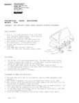
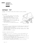
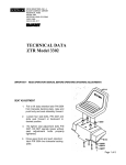
9/89 (Revised)
Page 1
TECHNICAL DATA BROCHURE
(MODEL ZTR 304)
IMPORTANT - READ OPERATOR'S MANUAL BEFORE OPERATING OR MAKING ADJUSTMENTS
BODY REMOVAL
1.
2.
3.
The 304 has a (2) piece fabricated s t e e l body. The upper body can be folded
forward to expose t h e t r a n s a x l e . In s o m e cases, it may be necessar y to remove
the upper body to s e r v i c e t h e transaxle.
\
To remove upper body, fold f o r w a r d and r e m o v e bolt (P/N 3006) from cable (P/N
3780). Shut upper body and remove the t w o c o t t e r pines (P/N 3058) fro m t h e
front of upper body s u p p o r t . C a r e f u l l y l i f t upper body from frame.
Reverse above procedure to reinstall.
SEAT ADJUSTMENT
1.
2.
3.
Raise upper body.
Loosen four seat bolts (P/N 3093) and slide seat forward or backward to
desired position.
Retighten bolts.
MOWER BLADE OPERATION
To engage the mower blades, t u r n lever on floor slowly to the "ON" position. To
disengage mower blades, t u r n l e v e r slowly to the "OFF" position.
REMOVING MOWER DECK
1.
2.
3.
4.
5.
6.
7.
*
Loosen the belt keeper (P/N 7 0 2 6 & 7 0 2 7 ) , located under the engine, by l o o s i n g
t w o r e a r engine mounting b o l t s , allowing the deck d r i v e belt to come f r e e of the
r e a r pulley.
Disconnect the wiring loom at t h e deck s a f e t y switch (P/N 4242).
Remove* the two clevis pins (P/N 3 0 7 2 ) f r o m the two r e a r L- r o d s (P/N 1355) and
slide f r o m slots.
Remove clevis pins (P/N 3 0 7 2 ) L-rod a t t a c h e d to l i f t handle and slide from slot.
Remove clevis pin (P/N 3072) f r o m f r o n t deck hanger' s h a f t (P/N 1332), located at
f r o m of mower deck on slide p l a t e s w e l d e d at b a t t e r y box and remove.
Lift front of mower c h a s s i s and roll f r e e of t h e deck.
To install, reverse the above procedure.
IDJUSTMENT OF MOWER DECK DRIVE BELT
1.
2.
3.
4.
5.
6.
The m o w e r deck d r i v e belt is tensioned by a spring loaded engagement idler
quadrant.
This system is designed to maintain the proper belt tension at all times.
Belt tension can be adjusted by moving the engaging rod (P/N 7013) into the
outside hole of engagement handle (P/N 7020).
After belt tension is adjusted, check to assure that the mower blade will not
t u r n freely when the engaging rod is in the "OFF" position.
If the mower blade .urns freely, adjust the blade by loosening*nut' (P/N 3205) at
end of the brake linkage (P/N 7015).
After adjustment is achieved, perform the safety checks listed below.
Page 2
"IMPORTANT" - PERFORM SAFETY CHECKS AFTER MAKING ANY REPAIRS OR ADJUSTMENTS
1.
A f t e r reassembly, while seated on mower attempt to s t a r t engine w i t h mower
deck engaged. Engine should not start. If engine does s t a r t , r e t u r n the mower
to an Authorized Dixon Dealer f o r adjustment or repair.
2.
Disengage mower deck and s t a r t engine. With the operator in the normal
seated position, engage mower deck and remove weight from seat. The engineshould stop. If the engine does not stop when operator rises from seat, return the
mower to an Authorized Dixon Dealer f o r adjustment or repair.
3.
Engage, then disengage, mower blade in each cutting height. Insure that
blade disengages and comes to a stop w i t h i n (5) seconds in each height position.
If blade does not disengage properly contact your A u t h o ri z e d Dixon Dealer.
PARKING BRAKE ADJUSTMENT
1. Raise upper body to the open position.
2. Tighten nut on brake rod (P/N 2533) located in front of the transaxle
on each side, just enough to prevent brake from slipping when engaged.
CAUTIQN: Over tightening may cause premature wear on the brake bank (P/N
5085).
REMOVING THE MOWER BLADE
Secure blade (P/N 2483) from turning. Remove blade bolt from center (P/N
3268), lock washer (P/N 3065) and blade washer (P/N 6113), then blade (P/M
2483). To reinstall, reverse above procedure. . WARNING; Sharp edges on
blade can cause injury!
Caution should be exercised when service is required on blade.
(P/N 8112)
DIXON INDUSTRIES, INC.
Box 1569
Coffeyville. Kansas 67337-0945
(316) 251-2000
TELEX: 417109
Airport Industrial Park
Page 3
Page 4
Page 5
Page 6
Page 7