1
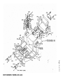
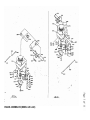
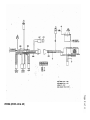
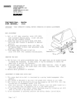
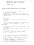
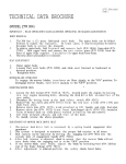
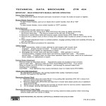
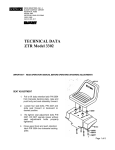
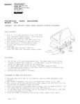
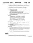
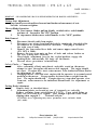
TECHNICAL DATA BROCHURE - ZTR 428 & 429
DATE 8/89 (Rev.)
PAGE 1 of 11
MPORTANT -- READ OPERATOR’S MANUAL BEFORE OPERATING OR MAKING ADJUSTMENTS.
Deluxe Seat Adjustment
Easy hand lever action allows forward and backward movement, of seat.
No bolts to loosen or tighten.
Mower Blade Operation
1.
To start mower blades, pull up slightly on blade drive switch handle
and move it forward to the "ON" position.
2.
To stop mower blades, move switch handle to the "OFF" position.
Body Removal
1.
Disconnect throttle cable from engine.
2.
Disconnect rear wiring loon from the body-by turning the threaded collar
on connector in a counterclockwise direction. This plug is located at
the right rear of body.
3.
Remove the four control lever bolts and remove upper control levers
(P/N 9079 A 9080).
4.
Remove the two acorn nuts on floor of body and release latches on
the rear of body near each side.
5.
Place height adjustment lever in the vertical position, engage the
parking brake and carefully l i f t body off the chassis.
6.
Reverse above procedures to install body.
S a f e t y Checks -- "Important"
1.
After reassembly of body onto chassis and while seated on the mower,
attempt to start the engine with mower deck engaged. The engine should
not start. If engine does start, return mower to an Authorized Dixon Dealer
for adjustment or repair.
2.
Disengage mower deck and start engine with the operator in a normal seated
position on the mower. Engage mower deck and remove weight from the
seat. The engine should stop. If engine does not stop when operator rises
from seat, return mower to an Authorized Dixon Dealer for adjustment or
repair.
Parking Brake Adjustment
1.
Remove body as described above.
2.
Adjustment points are located at rear of transaxle on each side.
Remove roll pins from swivel fitting (P/N 2172). Turn swivel fitting on
brake rod (P/N 6100) in, to tighten. Just enough to prevent brake from
slipping when engaged. 3.
Reinstall roll pin.
CAUTION: Over tightening may cause premature wear, on bra ke band
(P/N 6085).
Dixon Industries, INC.
Box 1569
Coffeyville, Kansas 67337-0945
(316)251-2000
TELEX: 417109
Airport Industrial Park
CHASSIS ASSEMBLY (MODEL 429 & 428)
BODY ASSEMBLY (MODEL 429 & 428)
ENGINE ASSEMBLIES (MODEL 429 & 428)
WIRING (MODEL 429 & 428)
Page 11 of 11
Note: It is possible to install the engine to mower deck drive belt (P/N
0111) at this time; however, our engine Manufacturers have suggested that
this, belt be installed a f t e r the engine has been fully serviced per
Manufacturers' suggestions and allowed to operate at 1/2 to 3/4 throttle
settings for approximately (3) Minutes.
This will place the initial start up of
the engine in a no load situation and allow complete engine lubrication.
Adjustment;
1.
Install engine to Mower deck drive belt (P/N 6111).
2.
Check and adjust tire pressures.
Front 19 to 21 psi; Rear 8 to 12 psi.
Tires May have been over inflated for shipping purposes.
3.
Place the Mower on a level surface. Using the lift handle, raise the
Mower deck to a height which will allow Measurements to be taken from
the surface to the tops of the two outer Mower deck cutter blades (P/N
8688).
4.
Align both outer Mower deck cutter blades to obtain a side to side
Measurement. Starting with the left blade as viewed from operator's position,
secure Measurement from level surface to the bottom of the - cutter blade tip,
rotate blade and check Measurement on opposite end of cutter blade. Tip to
tip measurement on the same cutter blade should not vary more than 1/8th of an
inch. Maintain measurement taken and verify against the right outer cutter
blade. If adjustment is required, loosen or tighten the nuts on the two rear Lrods.
5.
Align both outer mower deck cutter blades front to rear as viewed from
operator's position. Measure from surface to the bottom of the cutter blade
tip, at the rear of the mower deck. Using the nut on the single front L-rod,
loosen or tighten as required to place the mower deck at an attitude of
approximately l/8th of an inch higher in the rear than the front of the deck.
6.
Recheck belt routing and alignment, start engine, burnish in electric blade
clutch using at least (5) engagements at 3/4 to full throttle settings. Each
engagement should last approximately (6) seconds.
Note; The completed adjustment places the mower deck in an attitude or
position which will produce a quality cut. Ground speed, grass conditions,
types of grass, tire pressures, dull or bent blades and loose belts are just
some of the factors which will cause poor cut quality.
DIXON INDUSTRIES, INC.
Box1569
Coffeyville, Kansas 67337-0945
(316)251-2000
TELEX 417100
Airport Industrial Park