1
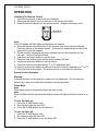
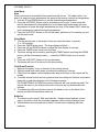
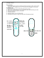
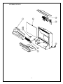
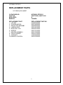
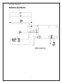
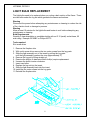
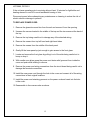
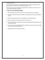
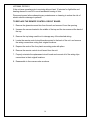
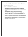
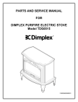
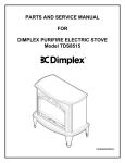
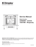
PARTS AND SERVICE MANUAL
FOR THE 23” INSERT FIREPLACE
MODEL NUMBER:
HFPI9280
DFPI2311
TABLE OF CONTENTS
OPERATION
PAGE 1
PARTS DRAWING
PAGE 5
PARTS LIST
PAGE 6
WIRING SCHEMATICS
PAGE 7
LIGHT BULB REPLACEMENT
PAGE 8
MANUAL CONTROL ON/OFF SWITCH REPLACEMENT
PAGE 9
FLAME MOTOR/FLAME ROD REPLACEMENT
PAGE 10
POWER CORD REPLACEMENT
PAGE 12
HEATER ASSEMBLY REPLACEMENT
PAGE 13
REMOTE CONTROL CIRCUIT BOARD REPLACEMENT
PAGE 14
HEATER DISABELER SWITCH REPLACEMENT
PAGE 15
HFPI9280, DFI2311
OPERATION
Initializing The Remote Control
1. Turn on the electrical power at the circuit breaker.
2. Slide open the battery cover on the back of the remote transmitter.
3. Install three AAA batteries into the remote control. Replace the battery cover.
Note:
The LCD display will flash when new batteries are inserted.
4. Move the remote transmitter close to the fireplace (less than five feet preferred).
Press any button on the remote control. The remote is transferring the code to the
receiver built into the fireplace.
5. Set the clock by depressing the button marked clock on the transmitter for five
seconds. The hour display will flash.
6. Use the up and down buttons to set the hour.
7. Press the clock button again and the minute display will flash.
8. Use the up and down buttons to set the minute.
9. Press the clock button again and the 0F or 0C display will flash.
10. Use the up and down buttons to select the remote to display temperature in 0F or 0C
11. Press the clock button again. The remote control is now ready for operation.
Remote Control Operation
Warning
It takes some time for the receiver to respond to the transmitter. Do not press the
buttons more than once within two seconds for correct operation.
Flame Mode
Note
When flame mode is activated the flame will turn on only.
Note
When the flame button is pressed the display screen will display the flame status on or
off.
To turn the flame on:
1. Press the FLAME button once.
2. The display screen will read OFF.
3. Press the FLAME button turn the flame on.
To turn the flame off:
1. Press the FLAME button once.
2. The display screen will read ON.
3. Press the FLAME button to turn the flame OFF.
1
HFPI9280, DFI2311
Auto Mode
Note
When auto mode is activated the flame and heat will turn on. The heater will turn on
and off to keep the room temperature the same as the remote controls set temperature.
1. Use the UP and DOWN buttons to set the desired target temperature.
2. Press the AUTO/OFF button once to activate the auto mode. In auto mode the
remote transmitter will automatically turn on the flame and heater when the room
temperature is below the target temperature and turn off the heater ONLY when the
room temperature is above the target temperature.
3. Press the AUTO/OFF button to turn off the heater and flame (if it is already on) and
exit the auto mode.
Sleep Mode
1. You can set the timer to the length of time you want the heater to operate
(1 to 120 minutes).
2. Press the TIMER button once. The timer display will blink --3. Press the UP and DOWN buttons to adjust the timer display in minutes.
4. Press the TIMER button once to set the timer.
5. The timer setting can be reset by pressing the TIMER button and using the DOWN
button until the timer display reads ----, press the TIMER button once to set the
timer.
6. Press the AUTO/OFF button to turn on the heater.
7. The heater will turn off at the end of the timer setting.
Child Proof Function
1. Remove the battery cover on the back of the remote control.
2. Slide the small blue switch down to activate the child proof function.
3. Child Proof will appear on the display screen and all function on the remote will be
locked.
4. To enable normal remote control operation when the child proof function is activated,
press the up and down buttons in the following sequence,
UP-DOWN-DOWN-UP-DOWN the remote functions will now operate normally. The
remote will return to the child proof function if buttons are not pressed after two
minutes.
5. To disable the child proof function remove the battery cover on the back of the
remote and slide the small blue switch up.
Batteries
1. The remote control uses 3 AAA size batteries. Replace these batteries at least
every 6 months or when the low battery appears on the remote display screen.
2. When batteries are removed wait at least 1 minute before replacing with new
batteries.
2
HFPI9280, DFI2311
Code selection
If the current remote control is interfering with the operation of other remote control
devices (TV, VCR, garage doors etc.) The code can be changed on the remote.
To change code:
1. Remove the battery cover on the back of the remote control.
2. Slide the four small switches to any configuration other than the factory set code.
3. Remove the batteries, wait for one minute.
4. Install the batteries.
5. Install the battery cover onto the remote.
6. Reinitialize the remote to match the new code to the masonry insert.
3
HFPI9280, DFPI2311
OPERATION
Masonry Insert Manual Control
1. The masonry insert has a manual power ON/OFF switch located in the upper corner
of the unit.
2. To operate press the switch once, to turn the unit on. A red light will illuminate to
indicate the power is on. Press the switch again to turn the unit off.
Note
When the manual power switch is used the heater will run.
The manual ON/OFF switch is to be used only when the remote transmitter is OFF.
4
HFPI9280, DFPI2311
5
HFPI9280, DFPI2311
REPLACEMENT PARTS
23” FIREPLACE INSERT
CATALOGUE NO.
PART NO.
MOD LEVEL:
MADE IN:
HFPI9280, DFPI2311
6900770259, 6900770159
A
CANADA
REPLACEMENT PART
1. LOG SET
2. FLICKER MOTOR
3. REFLECTOR ASSEMBY
4. LAMPHOLDER
5. BULB, 60W 120V
6. MIRROR
7. HEATER ASSEMBLY
8. CIRCUIT BOARD
9. CORD SET
10. REMOTE CONTROL
REPLACEMENT PART NO.
0438200200RP
2000140500RP
5900080600RP
2500140100RP
4200020100RP
5900170100RP
2000170300RP
3000210100RP
4100040400RP
3000210300RP
6
HFPI9280, DFPI2311
WIRING DIAGRAM
7
HFPI9280, DFPI2311
LIGHT BULB REPLACEMENT
The light bulbs need to be replaced when you notice a dark section of the flame. There
are two bulbs under the log set which generate the flames and embers.
Warning
Disconnect the power before attempting any maintenance or cleaning to reduce the risk
of fire, electric shock or damage to persons.
Warning
Allow at least 10 minutes for the light bulbs and heater to cool before attempting any
maintenance or cleaning.
Bulb Requirements
Quantity 2 clear chandelier or candelabra bulbs with an E-12 (small) socket base, 60
watt rating. Example GE 60BC or Philips 60CTC.
Tools required:
Slot screw driver
1. Remove the fireplace trim.
2. With a slot screw driver remove the two outer screws from the log grate.
3. Slide the light assembly out of the insert by pulling the log grate
until the light assembly reaches the stop (approximately 2”)
4. Remove the log set by lifting straight up.
5. Examine the bulb(s) to determine which bulb(s) require replacement.
6. Unscrew the bulbs counter clockwise.
7. Insert new bulbs.
8. Replace the log set into the insert.
9. Slide the light assembly back into the insert.
10. Install the two outer screws into the log grate.
11. Reinstall the fireplace trim.
8
HFPI9280, DFPI2311
If the unit was operating prior to servicing allow at least 10 minutes for light bulbs and
heating element to cool off to avoid accidental burning of skin.
Disconnect power before attempting any maintenance or cleaning to reduce the risk of
electric shock or damage to persons.
TO REPLACE MANUAL CONTROL ON/OFF SWITCH
1. Remove the glass doors and trim from the unit and remove it from the opening.
2. Unscrew the screws located in the middle of the top and the two screws at the back of
the top.
3. Remove the top being careful not to damage any of the attached wiring.
4. Disconnect the wiring switch harness from the circuit board by gently pulling.
5. Locate and remove the manual control on/off switch located in the front corner of the
unit by depressing the retainer clips on the rear of the switch and pushing the switch
out of the front of the unit.
6. Properly orientate the new switch and connect all of the wiring clips and
connections.
7. Reassemble in the reverse order as above.
9
HFPI9280, DFPI2311
If the unit was operating prior to servicing allow at least 10 minutes for light bulbs and
heating element to cool off to avoid accidental burning of skin.
Disconnect power before attempting any maintenance or cleaning to reduce the risk of
electric shock or damage to persons.
TO REPLACE FLAME MOTOR/FLAME ROD
1. Remove the glass doors and trim from the unit and remove it from the opening.
2. Unscrew the screws located in the middle of the top and the two screws at the back of
the top.
3. Remove the top being careful not to damage any of the attached wiring.
4. Remove the screws from top left hand and right hand sides.
5. Remove the screws from the middle of the back panel.
6. Gently lift the inner panel up just enough to gain access to the front glass.
7. Locate and remove the front glass by pulling it out of the slots being careful not to
bump or drop it.
8. Locate the flame motor and flame rod assembly, remove the motor mounting screws
with a short handled screw driver.
9. With needle nose pliers grasp the motor wiring strain relief grommet from inside the
cover and push while twisting to remove.
10. Locate and remove the wiring connections and remove the flame rod and flame
motor assembly.
NOTE: When removing the flame motor some damage may occur to the flame rod.
If flame rod is damaged replace to insure proper operation.
11. To remove the flame rod attach needle nose pliers to the spring on the motor shaft
and pull while rotating in the opposite direction of the spring winding.
12. To replace the flame rod attach needle nose pliers to the flame rod spring and push
onto the flame motor shaft while rotating in the opposite direction of the spring
winding.
13. Properly orientate the flame motor and connect all of the wiring clips connections in
their original locations.
10
HFPI9280, DFPI2311
If the unit was operating prior to servicing allow at least 10 minutes for light bulbs and
heating element to cool off to avoid accidental burning of skin.
Disconnect power before attempting any maintenance or cleaning to reduce the risk of
electric shock or damage to persons.
TO REPLACE FLAME MOTOR/FLAME ROD
14. Install the flame motor strain relief grommet on the motor wiring and insert into the
hole in the cover.
15. Reassemble in the reverse order as above.
11
HFPI9280, DFPI2311
If the unit was operating prior to servicing allow at least 10 minutes for light bulbs and
heating element to cool off to avoid accidental burning of skin.
Disconnect power before attempting any maintenance or cleaning to reduce the risk of
electric shock or damage to persons.
TO REPLACE POWER CORD
1. Remove the glass doors and trim from the unit and remove it from the opening.
2. Unscrew the screws located in the middle of the top and the two screws at the back of
the top.
3. Remove the top being careful not to damage any of the attached wiring.
4. Remove the screws from top left hand and right hand sides.
5. Remove the screws from the middle of the back panel.
6. Gently lift the inner panel up just enough to gain access to the front glass.
7. Locate and remove the front glass by pulling it out of the slots being careful not to
bump or drop it.
8. With needle nose pliers grasp the power cord strain relief grommet from inside the
cover and push while twisting to remove.
9. Remove the power cord wiring connections from the circuit board being careful not to
damage the terminal connections.
10. Install the new power cord through the hole in the cover and connect all of the wiring
connections in their original locations.
11. Install the power cord retaining grommet on the power cord and insert into the hole
in the cover.
12. Reassemble in the reverse order as above.
12
HFPI9280, DFPI2311
If the unit was operating prior to servicing allow at least 10 minutes for light bulbs and
heating element to cool off to avoid accidental burning of skin.
Disconnect power before attempting any maintenance or cleaning to reduce the risk of
electric shock or damage to persons.
TO REPLACE THE HEATER ASSEMBLY
1. Remove the glass doors and trim from the unit and remove it from the opening.
2. Unscrew the screws located in the middle of the top and the two screws at the back of
the top.
3. Remove the top being careful not to damage any of the attached wiring.
4. Remove the heater mounting screws from the top of the unit.
5. Disconnect the wiring clips and connections noting their original locations and remove
the heater assembly.
6. Properly orientate the replacement heater assembly and connect all of the wiring clips
connections in their original locations.
7. Reassemble in the reverse order as above.
13
HFPI9280, DFPI2311
If the unit was operating prior to servicing allow at least 10 minutes for light bulbs and
heating element to cool off to avoid accidental burning of skin.
Disconnect power before attempting any maintenance or cleaning to reduce the risk of
electric shock or damage to persons.
TO REPLACE THE REMOTE CONTROL CIRCUIT BOARD
1. Remove the glass doors and trim from the unit and remove it from the opening.
2. Unscrew the screws located in the middle of the top and the two screws at the back of
the top.
3. Remove the top being careful not to damage any of the attached wiring.
4. Locate the remote control circuit board mounted to the back of the unit and remove
the wiring connections noting their original locations.
5. Depress the ends of the four plastic mounting posts with pliers.
6. Remove the remote control circuit board from the unit.
7. Properly orientate the replacement circuit board and connect all of the wiring clips
connections in their original locations.
8. Reassemble in the reverse order as above.
14
HFPI9280, DFPI2311
If the unit was operating prior to servicing allow at least 10 minutes for light bulbs and
heating element to cool off to avoid accidental burning of skin.
Disconnect power before attempting any maintenance or cleaning to reduce the risk of
electric shock or damage to persons.
TO REPLACE THE HEATER DISABELER SWITCH
1. Remove the glass doors and trim from the unit and remove it from the opening.
2. Unscrew the screws located in the middle of the top and the two screws at the back of
the top.
3. Remove the top being careful not to damage any of the attached wiring.
4. Locate and remove the heater disabler switch located on the side of the unit by
depressing the retainer clips on the rear of the switch and pushing the switch out of
the front of the unit.
5. Disconnect the wiring clips and connections noting their original locations and remove
the heater assembly.
6. Properly orientate the new switch and connect all of the wiring clips and connections.
7. Reassemble in the reverse order as above.
15