1
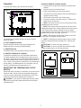
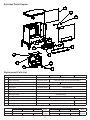
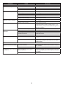
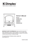
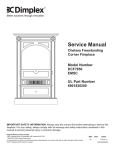
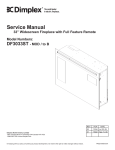
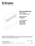
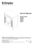
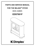
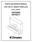
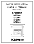
Service Manual
Model Number
CDS6599 - Celeste
TDS7599 - Rhapsody
IMPORTANT SAFETY INFORMATION: Always read this manual first before attempting to service this
fireplace. For your safety, always comply with all warnings and safety instructions contained in this
manual to prevent personal injury or property damage.
Dimplex North America Limited
1367 Industrial Road Cambridge ON Canada N1R 7G8
1-888-346-7539 www.dimplex.com
In keeping with our policy of continuous product development, we reserve the right to make changes without
notice.
© 2012 Dimplex North America Limited
7400340000R02
Table Of Contents
Operation. . . . . . . . . . . . . . . . . . . . . . . . . . . . . . . . . . . . . . . . . . . . . . . . . . . . . . . . . . . . 3
Maintenance . . . . . . . . . . . . . . . . . . . . . . . . . . . . . . . . . . . . . . . . . . . . . . . . . . . . . . . . . 4
Exploded Parts Diagram. . . . . . . . . . . . . . . . . . . . . . . . . . . . . . . . . . . . . . . . . . . . . . . . 5
Replacement Parts List. . . . . . . . . . . . . . . . . . . . . . . . . . . . . . . . . . . . . . . . . . . . . . . . . 5
Wiring Diagram - MOD 0-A. . . . . . . . . . . . . . . . . . . . . . . . . . . . . . . . . . . . . . . . . . . . . . 6
Wiring Diagram - MOD B & C. . . . . . . . . . . . . . . . . . . . . . . . . . . . . . . . . . . . . . . . . . . . 6
Wiring Diagram - MOD D. . . . . . . . . . . . . . . . . . . . . . . . . . . . . . . . . . . . . . . . . . . . . . . . 6
Switch Replacement - On/Off and Heater. . . . . . . . . . . . . . . . . . . . . . . . . . . . . . . . . . . 7
Light Dimmer Replacement (MOD 0-C) . . . . . . . . . . . . . . . . . . . . . . . . . . . . . . . . . . . . 7
Light Dimmer Replacement (MOD D). . . . . . . . . . . . . . . . . . . . . . . . . . . . . . . . . . . . . . 7
Flicker Motor/Flicker Rod Replacement (Mod 0-A). . . . . . . . . . . . . . . . . . . . . . . . . . . . 7
Flicker Motor/Flicker Rod Replacement (Mod B-D). . . . . . . . . . . . . . . . . . . . . . . . . . . . 8
Thermostat Replacement . . . . . . . . . . . . . . . . . . . . . . . . . . . . . . . . . . . . . . . . . . . . . . . 8
Heater Assembly Replacement. . . . . . . . . . . . . . . . . . . . . . . . . . . . . . . . . . . . . . . . . . . 9
Light Transformer Replacement (Mod 0-A). . . . . . . . . . . . . . . . . . . . . . . . . . . . . . . . . . 9
Light Transformer Replacement (Mod B-C). . . . . . . . . . . . . . . . . . . . . . . . . . . . . . . . . 9
Power Cord Replacement. . . . . . . . . . . . . . . . . . . . . . . . . . . . . . . . . . . . . . . . . . . . . . . 9
Troubleshooting Guide . . . . . . . . . . . . . . . . . . . . . . . . . . . . . . . . . . . . . . . . . . . . . . . . 11
Always use a qualified technician or service agency to repair this fireplace.
! NOTE: Procedures and techniques that are considered important enough to emphasize.
CAUTION: Procedures and techniques which, if not carefully followed, will result in damage to the
equipment.
WARNING: Procedures and techniques which, if not carefully followed, will expose the user to the
risk of fire, serious injury, or death.
2
Operation
OPTIONAL REMOTE CONTROL USAGE
1. Plug the stove into the outlet located on the side of the
receiver.
2. Plug the receiver into the wall outlet.
3. Install a 9 volt battery into the remote control.
4. Turn the stove’s On/Off switch to the On position prior to
using the remote control.
5. The remote control works up to 50 feet away.
6. Push the On button to turn the stove On. Push the Off
button to turn the stove off.
! NOTE: To prevent the risk of fire, the stove plug must be
inserted fully into the receiver.
! NOTE: The remote control and receiver use one of 243
independent frequencies. When replacing the remote control
or the receiver they must be replaced as a set to ensure
proper operation. The frequency of the remote is located on
the back of the remote on a label. (Figure 2)
! NOTE: The fireplace On/Off switch must be in the ON
position prior to using the Remote Control.
To access the controls, go to the back of the stove.
Figure 1
A
B
C
D
A. ON/OFF SWITCH
The On/Off switch supplies power to all stove functions
(heater & flame).
! NOTE: On/Off Remote Control may be used to control
most other electrical devices including T.V.’s, stereos and
lamps.
B. LIGHT DIMMER CONTROL
Controls the light intensity of the log bed display area.
Rotate the knob to choose the desired setting.
CAUTION: For indoor use in dry areas only
CAUTION: For use on 120 VAC electrical devices with
15 amp resistive load or 1/3 HP inductive load.
C. HEATER SWITCH
The heater switch turns the heater function on and off.
Figure 2
D. HEATER THERMOSTAT CONTROL
To adjust the temperature to your individual requirements,
turn the thermostat control clockwise all the way to turn on
the heater. When the room reaches the desired temperature,
turn the thermostat knob counter clockwise until you hear a
click. Leave in this position to maintain the room temperature
at this setting. For additional heat, turn clockwise until you
hear the click again and the heater will turn on.
RESETTING THE TEMPERATURE CUTOFF
SWITCH
OPEN
Should the heater overheat, an automatic cut out will turn the
heater off and it will not come back on without being reset.
It can be reset by switching the On/Off Switch to OFF and
waiting 5 minutes before switching the unit back on.
CAUTION: If you need to continuously reset the heater,
unplug the unit and call Dimplex North America Limited at
1-800-346-7539.
3
Maintenance
Figure 4
W
ARNING: Disconnect power before attempting any
maintenance or cleaning to reduce the risk of fire, electric
shock or damage to persons.
LIGHT BULB REPLACEMENT
CAUTION: Allow at least 5 minutes for light bulbs to cool
off before touching bulbs to avoid accidental burning of skin.
Light bulbs need to be replaced when you notice a dark
section of the flame or when the clarity and detail of the log
exterior disappears. There are two bulbs under the log set
which generate the flames and embers.
Tools Required: Flat head Screwdriver
Helpful Hints: It is a good idea to replace all light bulbs at
one time if they are close to the end of their rated life. Group
replacement will reduce the number of times you need to
open the unit to replace light bulbs.
LOWER LIGHT BULB REQUIREMENTS:
MOD 0-A: 3 - 35 watt, 12 volt, Narrow spot Halogen bulb DO
NOT EXCEED 35 WATTS PER BULB
1. Remove the light cover mounting screws located on the
rear cover and remove the light cover being careful not to
damage any of the wiring or light bulbs.
2. Remove the burnt out bulb(s) by pulling straight out of
socket. If bulbs are difficult to remove from socket move
the bulb from side to side while pulling being careful not
to damage the light socket.
3. Replace the upper light bulb.
UPPER LIGHT BULB REQUIREMENTS:
MOD 0-C: 1 - 25 watt, 12 volt, 1156 Incandescent automotive
bulb. DO NOT EXCEED 25 WATTS
MOD D: 1 –15 watt candelabra E12 small base 120 volt. DO
NOT EXCEED 15 WATTS
1. Remove the stove pipe kit (if equipped).
2. Remove the 2 screws at the upper corners of the back
panel. (Figure 3) Lift the back end of the top to clear the
brackets and pull back. Lift top carefully, and place to
the side of the stove. Caution should be taken as the top
mounting brackets may scratch the finish.
3. Remove the burnt out bulb by pushing in and turning
counter-clockwise.
4. Replace the upper light bulb.
5. Reassemble in the reverse order as above.
4. Reassemble in the reverse order as above.
MOD B-D: 3 – 35 watt Halogen Quartz lamps, 120 volt, G9
base. DO NOT EXCEED 35 WATTS PER BULB
1. Remove the stove pipe kit (if equipped).
2. Gently place stove on its back on a flat surface.
3. Remove the heater cover retaining screws located on the
bottom of the stove and lower heater and light assembly
out onto the floor. (Figure 4)
4. Remove the burnt out bulb(s) by pulling straight out of
socket. If bulbs are difficult to remove from socket move
the bulb from side to side while pulling being careful not
to damage the light socket.
5. Replace the lower light bulbs.
6. Reassemble in the reverse order as above.
Figure 3
GLASS CLEANING
The clear door is cleaned in the factory during the assembly
operation. During shipment, installation, handling, etc., the
clear door may collect dust particles, these can be removed
by dusting lightly with a clean dry cloth.
To remove fingerprints or other marks, the clear door can
be cleaned with a damp cloth. The clear door should be
completely dried with a lint free cloth to prevent water spots.
To prevent scratching, do not use abrasive cleaners or spray
liquids on the clear door surface.
STOVE SURFACE CLEANING
Use warm water only to clean painted surfaces of the
Compact Stove. Do not use abrasive cleaners.
4
Exploded Parts Diagram
4
11
1
12
5
2
6
9
7
10
8
Replacement Parts List
MOD Level
NONE & MOD. A
MOD. B
MOD. C
1.
On/Off Switch
2.
Heater Assembly
3.
Log Set
4.
Partially Reflective Glass
6900100600RP
5900060600RP
5.
Flicker Rod
6900490100RP
5900080600RP
6.
Flicker Motor
2000140300RP
7.
Thermostat
2300150100RP
8.
Thermostat Knob
8800000300RP
9.
Transformer
2800070200RP
2000230100RP
6902430100RP (send 7206920100R01)
Not Available
2100170100RP
10. Power Cord
11.
0438200200RP
2100160100RP
N/A
4100040300RP
Upper Light Harness with Light Dimmer
12. Lower Light Harness
MOD. D
2500120100RP
Not Available
2500110100RP
2500290100RP
2500280100RP
Replacement Panels
CDS6599
TDS7599
Cream
Gloss Black
Flat
Green
Black
Right Side
Top
Left Side
Right Side
Top
Not Available
Not
Not Available
Not
1103270581RP 1103270681RP Not Available Available 1103270504RP 1103270604RP Not Available Available
Left Side
5
Wiring Diagram - MOD 0-A
Wiring Diagram - MOD B & C
Wiring Diagram - MOD D
6
Switch Replacement - On/Off and Heater
wiring clips and connections.
9. Reassemble in the reverse order as above.
W
ARNING: If unit was operating prior to servicing allow
at least 10 minutes for light bulbs and heating element to
cool off to avoid accidental burning of skin.
W
ARNING: Disconnect power before attempting any
maintenance or cleaning to reduce the risk of electric
shock or damage to persons.
Tools Required: Phillips head Screwdriver
1. Remove the stove pipe kit (if equipped).
2. Remove the 2 screws at the upper corners of the back
panel. Lift the back end of the top to clear the brackets
and pull back. Lift top carefully, and place to the side of
the stove. Caution should be taken as the top mounting
brackets may scratch the finish.
3. Locate the switch, that requires replacement, mounted
on the rear panel and disconnect the wiring clips and
connections, noting their original locations.
! NOTE: A flat head screwdriver can be used to gently pry
between the end of the connector and the switch to release
the wires.
4. Depress the retainer clips on the rear of the switch and
push the switch out of the rear cover.
5. Properly orient the new switch and reconnect all of the
wiring clips and connections.
6. Reassemble in the reverse order as above.
Light Dimmer Replacement (MOD D)
W
ARNING: If unit was operating prior to servicing allow
at least 10 minutes for light bulbs and heating element to
cool off to avoid accidental burning of skin.
W
ARNING: Disconnect power before attempting any
maintenance or cleaning to reduce the risk of electric
shock or damage to persons.
Tools Required: Phillips head Screwdriver
1. Remove the stove pipe kit (if equipped).
2. Remove the 2 screws at the upper corners of the back
panel. Lift the back end of the top to clear the brackets
and pull back. Lift top carefully, and place to the side of
the stove. Caution should be taken as the top mounting
brackets may scratch the finish.
3. Remove the upper light bulb, the light socket retaining
screw and the wiring from the wiring clip mounted to the
underside of the top.
4. Locate the light dimmer, mounted on the rear panel, and
pull off the dimmer control knob.
5. Remove the light dimmer retaining nut.
6. Pull the light dimmer out from the back of the rear panel.
7. Gently place stove on its back on a flat surface.
Light Dimmer Replacement (MOD 0-C)
8. Remove the heater cover retaining screws located on the
bottom of the stove and lower heater and light assembly
out onto the floor.
W
ARNING: If unit was operating prior to servicing allow
at least 10 minutes for light bulbs and heating element to
cool off to avoid accidental burning of skin.
W
ARNING: Disconnect power before attempting any
maintenance or cleaning to reduce the risk of electric
shock or damage to persons.
Tools Required: Phillips head Screwdriver
Flat Head Screwdriver
1. Remove the stove pipe kit (if equipped).
2. Remove the 2 screws at the upper corners of the back
panel. Lift the back end of the top to clear the brackets
and pull back. Lift top carefully, and place to the side of
the stove. Caution should be taken as the top mounting
brackets may scratch the finish.
3. Remove the upper light bulb, the light socket retaining
screw and the wiring from the wiring clip mounted to the
underside of the top.
4. Locate the light dimmer, mounted on the rear panel, and
pull off the control knob.
5. Remove the light dimmer retaining nut.
6. Pull the light dimmer out from the back of the rear panel.
7. Locate the wiring connections for the light dimmer and
disconnect the wiring connections, noting their original
locations.
! NOTE: In some models you will be required to remove
the light cover mounting screws to complete the replacement.
Remove the light cover, being careful not to damage any of
the wiring or light bulbs.
8. Properly orient the new dimmer and reconnect all of the
9. Remove all of the mounting screws on the heater cover
and separate the cover from the heater and light assembly.
10. Locate the wiring connections for the light dimmer and
disconnect the wiring connection, noting its original location.
11. Properly orient the new dimmer and reconnect all of the
wiring clips and connections.
12. Reassemble in the reverse order as above.
Flicker Motor/Flicker Rod Replacement
(Mod 0-A)
W
ARNING: If unit was operating prior to servicing allow
at least 10 minutes for light bulbs and heating element to
cool off to avoid accidental burning of skin.
W
ARNING: Disconnect power before attempting any
maintenance or cleaning to reduce the risk of electric
shock or damage to persons.
Tools Required: Phillips head Screwdriver
1. Remove the stove pipe kit (if equipped).
2. Gently place stove front side up on a flat surface.
3. Remove the heater cover retaining screws located on the
bottom of the stove.
4. Lift stove back on its feet and remove the 2 screws at the
upper corners of the back panel. Lift the back end of the
7
top to clear the brackets and pull back. Lift top carefully, and place to the side of the stove. Caution should
be taken as the top mounting brackets may scratch the
finish.
5. Remove all of the rear cover retaining screw located at
the lower center of the rear cover.
6. Remove the light cover, being careful not to damage any
of the wiring or light bulbs.
7. Pull out on the rear cover, bowing it slightly, and remove
it from its mounting slot. When the cover is removed,
place it flat behind the stove being careful not to damage
any of the wiring.
8. Remove the partially reflective glass panel by sliding it up
through the top.
9. Locate the rear flicker assembly cover and slide it out
the open back, exposing the flicker motor and flicker rod
assembly.
10. Remove the mounting bracket retaining screws and slide
the log and ember assembly, with the flicker motor and
rod assembly, out through open back.
11. Locate the flicker motor and flicker rod assembly and
remove the wiring clips and connections located by the
heater assembly, noting their original locations.
12. Remove the flicker motor mounting screws and pull the
assembly out of the mounting bracket.
! NOTE: When removing the Flicker Rod, damage may
occur if bent excessively. If the Flicker Rod is damaged,
replace to ensure proper operation.
13. To remove the flicker rod, attach needle nose pliers to
the spring on the motor shaft and pull while rotating in
the opposite direction of the spring winding.
14. To remove the flicker motor you must first remove the
flicker rod (see above). Remove the motor mounting
screws and remove motor from the mounting bracket.
15. To replace the flicker rod attach needle nose pliers to the
flicker rod spring and push onto the flicker motor shaft
while rotating in the opposite direction of the spring winding.
16. Properly orient the flicker motor and reconnect all of the
wiring clips connections in their original locations.
17. Reassemble in the reverse order as above.
out onto the floor.
4. Remove all of the mounting screws on the heater cover
and separate the cover from the heater and light assembly.
5. Locate the flicker motor and flicker rod assembly and
remove the wiring clips and connections located by the
heater assembly, noting their original locations.
6. Remove the flicker motor mounting screws and pull the
assembly out of the mounting bracket.
! NOTE: When removing the flicker motor some damage
may occur to the flicker rod. If flicker rod is damaged replace
it, to ensure proper operation.
7. To remove the flicker rod, attach needle nose pliers to
the spring on the motor shaft and pull while rotating in
the opposite direction of the spring winding.
8. To remove the flicker motor you must first remove the
flicker rod (see above). Remove the motor mounting
screws and remove motor from the mounting bracket.
9. To replace the flicker rod attach needle nose pliers to the
flicker rod spring and push onto the flicker motor shaft
while rotating in the opposite direction of the spring winding.
10. Properly orient the flicker motor and reconnect all of the
wiring clips connections in their original locations.
11. Reassemble in the reverse order as above.
Thermostat Replacement
W
ARNING: If unit was operating prior to servicing allow
at least 10 minutes for light bulbs and heating element to
cool off to avoid accidental burning of skin.
W
ARNING: Disconnect power before attempting any
maintenance or cleaning to reduce the risk of electric
shock or damage to persons.
Tools Required: Phillips head Screwdriver
1. Remove the stove pipe kit (if equipped).
2. Gently place stove front side down on a flat surface.
3. Depending on the model, the light cover may need to be
removed, being careful not to damage any of the wiring
or light bulbs.
4. Remove all of the mounting screws on the heater cover
and separate the cover from the heater and light assembly.
5. Locate the thermostat mounted to the heater cover and
disconnect the wiring connections, noting their original
locations.
6. Pull off the thermostat control knob to expose the mounting screws.
7. Remove the mounting screws and remove the thermostat.
8. Properly orient the new thermostat and reconnect all of
the wires.
9. Reassemble in the reverse order as above.
Flicker Motor/Flicker Rod Replacement
(Mod B-D)
W
ARNING: If unit was operating prior to servicing allow
at least 10 minutes for light bulbs and heating element to
cool off to avoid accidental burning of skin.
W
ARNING: Disconnect power before attempting any
maintenance or cleaning to reduce the risk of electric
shock or damage to persons.
Tools Required: Phillips head Screwdriver
Needle Nose Pliers
1. Remove the stove pipe kit (if equipped).
2. Gently place stove on its back on a flat surface.
3. Remove the heater cover retaining screws located on the
bottom of the stove and lower heater and light assembly
8
Heater Assembly Replacement
disconnect the wiring connections, noting their original
locations.
10. Properly orient the new transformer and reconnect all of
the wiring connections.
11. Reassemble in the reverse order as above.
W
ARNING: If unit was operating prior to servicing allow
at least 10 minutes for light bulbs and heating element to
cool off to avoid accidental burning of skin.
W
ARNING: Disconnect power before attempting any
maintenance or cleaning to reduce the risk of electric
shock or damage to persons.
Tools Required: Phillips head Screwdriver
1. Remove the stove pipe kit (if equipped).
2. Gently place stove front side down on a flat surface.
3. Depending on the model, the light cover may need to be
removed, being careful not to damage any of the wiring
or light bulbs.
4. Remove the heater cover retaining screws located on the
bottom of the stove and lower heater and light assembly
out onto the floor.
5. Remove the mounting bracket screws and lower the
heater assembly from the bottom of the stove, being
careful not to damage any of the wiring.
6. Remove the heater mounting screws and remove the
heater assembly.
7. Disconnect the wiring clips and connections, noting their
original locations.
8. Properly orient the new heater assembly and reconnect
all of the wiring clips and connections.
9. Reassemble in the reverse order as above.
Light Transformer Replacement (Mod
B-C)
W
ARNING: If unit was operating prior to servicing allow
at least 10 minutes for light bulbs and heating element to
cool off to avoid accidental burning of skin.
W
ARNING: Disconnect power before attempting any
maintenance or cleaning to reduce the risk of electric
shock or damage to persons.
Tools Required: Phillips head Screwdriver
1. Remove the stove pipe kit (if equipped).
2. Gently place stove on its back on a flat surface.
3. Remove the heater cover retaining screws located on the
bottom of the stove and lower heater and light assembly
out onto the floor.
4. Remove all of the mounting screws on the heater cover
and separate the cover from the heater and light assembly.
5. The transformer is mounted beside the heater assembly.
Locate and remove the mounting screws and remove the
transformer from the heater-mounting bracket.
6. Locate the wiring connections for the transformer and
disconnect the wiring connections, noting their original
locations.
7. Properly orient the new transformer and reconnect all of
the wiring connections.
8. Reassemble in the reverse order as above.
Light Transformer Replacement (Mod
0-A)
W
ARNING: If unit was operating prior to servicing allow
at least 10 minutes for light bulbs and heating element to
cool off to avoid accidental burning of skin.
W
ARNING: Disconnect power before attempting any
maintenance or cleaning to reduce the risk of electric
shock or damage to persons.
Tools Required: Phillips head Screwdriver
1. Remove the stove pipe kit (if equipped).
2. Gently place stove front side down on a flat surface.
3. Depending on the model, the light cover may need to be
removed, being careful not to damage any of the wiring
or light bulbs.
4. Remove all of the mounting screws on the heater cover
and separate the cover from the heater and light assembly.
5. Remove the mounting bracket screws and lower the
heater assembly from the bottom of the stove, being
careful not to damage any of the wiring.
6. Remove the heater assembly mounting screws and
remove the heater assembly.
7. The transformer is mounted beside the heater assembly. Remove the transformer from the heater-mounting
bracket by removing the mounting screws.
8. It still attched, remove the light cover being careful not to
damage any of the wiring or light bulbs.
9. Locate the wiring connections for the transformer and
! NOTE: MOD D IS NOT EQUIPPED WITH A
LIGHT TRANSFORMER
Power Cord Replacement
W
ARNING: If unit was operating prior to servicing allow
at least 10 minutes for light bulbs and heating element to
cool off to avoid accidental burning of skin.
W
ARNING: Disconnect power before attempting any
maintenance or cleaning to reduce the risk of electric
shock or damage to persons.
Tools Required: Phillips head Screwdriver
Needle Nose Pliers
1. Remove the stove pipe kit (if equipped).
2. Gently place stove on its back on a flat surface.
3. Depending on the model, the light cover may need to be
removed, being careful not to damage any of the wiring
or light bulbs.
4. Remove the heater cover retaining screws located in the
center of the rear cover and on the bottom of the stove.
5. Remove all of the mounting screws on the heater cover
and separate the cover from the heater and light assembly.
6. Locate and disconnect the power cord wiring connec-
9
tions, noting their original locations.
7. With needle nose pliers grasp the power cord strain relief
grommet from inside the heater cover and push while
twisting to remove.
8. Pull the power cord out through the hole in the heater
cover.
9. Install the new power cord through the hole in the heater
cover and connect all of the wiring connections in their
original locations.
10. Install the power cord retaining grommet on the power
cord and insert into the hole in the heater cover.
11. Reassemble in the reverse order as above.
10
Troubleshooting Guide
PROBLEM
CAUSE
SOLUTION
General
Circuit breaker trips or fuse
blows when unit is turned on
Short in unit wiring.
Trace wiring in unit.
Improper circuit current rating
Additional appliances may exceed the current rating of
the circuit breaker or fuse. Plug unit into another outlet or
install unit on a dedicated 15 amp circuit.
Unit with a Remote Control turns
on or off by itself
Remote control has a similar frequency
to other remotes in the area.
Replace Remote Control. Initialize to Remote Control
Receiver
Radio frequency disturbance from outside sources.
Replace Remote Control and Receiver where necessary.
Initialize Remote Control and Receiver
Defective Remote Control Receiver
Replace Remote Control Receiver and initialize to Remote
Control.
Lights dim in room while the unit
is on
Unit is drawing close to circuit current
rating
Move the unit to another outlet or install unit on a dedicated 15 amp circuit
Power cord gets warm
Normal Operation
The power cord may get slightly warm to the touch when
the heater is on
Defective power cord
Replace power cord if cord gets hot to the touch.
Improper operation
Refer to Operation Section
Defective Light Dimmer
Replace Light Dimmer Components
Fireplace seems dark
Appearance
Fireplace does not turn on Manu- Improper operation
ally
No incoming voltage from the electrical
wall socket
Fireplace does not turn on using
the Remote Control
(If Applicable)
Refer to Operation Section
Check Fuse/Breaker Panel
Loose wiring
Check wiring connections
Defective On/Off Switch
Replace switch
Improper operation
Refer to Operation Section
Remote control not initialized to fireplace
Initialize the remote control
Remote Control not working
Install new battery into the Remote Control. Initialize Remote Control and Receiver, where necessary
Replace Remote Control or Receiver where necessary.
Initialize Remote Control and Receiver.
Flame Frozen
Flame not bright or flame not
visible
Defective Flicker Motor
Replace Flicker Motor
Loose wiring
Check wiring connections
Burnt out light bulbs
Replace light bulbs
Loose wiring
Check wiring connections
Defective light harness
Replace light harness
Log set dim, not glowing
Burnt out light bulbs
Replace burnt out light bulbs
Flame Shudder
Defective flicker motor
Replace flicker motor
Light leaking around the log set
Log set not positioned properly
Check log set for proper fit
Upper and Lower Lights not
working (Mod 0-C)
Defective transformer
Replace Transformer
11
PROBLEM
CAUSE
SOLUTION
Heater
Heater is not turning off
Heater is not turning on
Heater is turning off after a
couple of minutes of operation
Heater emits an odor
Heater fan turns on but heater
lacks heat
Heating element is glowing red
Improper operation
Refer to Operation Section
Defective Heater Switch
Replace Heater Switch
Defective Thermostat
Replace Thermostat
Improper operation
Refer to Operation Section
Loose Wiring
Trace wiring in unit
Defective Heater Switch
Replace Heater Switch
Defective Thermostat
Replace Thermostat
Defective Heater assembly
Replace Heater assembly
Build up of dirt/dust in Heater Assembly
Ensure that exterior intake louvers and firebox cavity are
free of dirt/dust.
Defective Heater Assembly
Replace Heater Assembly
Normal Operation
Normal operation is when the heater emits an odor for
a brief period after the heater is initially turned on. The
heater is burning off any dust accumulated during manufacturing or operation.
Defective Heater Assembly
Replace Heater Assembly
Improper operation
Refer to Operation Section
Loose wiring
Trace wiring in unit
Defective Thermostat
Replace Thermostat
Defective Heater Assembly
Replace Heater Assembly
Normal Operation
Small glowing sections of the element are considered
normal.
Defective heater assembly
If larger glowing sections are causing the heater to trip the
thermal cutout, unplug unit, discontinue use and replace
heater assembly.
Dirty Heater Assembly
Ensure that exterior intake louvers and firebox cavity are
free of dirt/dust.
Defective Heater Assembly
Replace Heater Assembly
Flicker rod hitting or rubbing against
internal components
Ensure rod is straight and mounted properly in the bracket, spinning freely away from other components. Replace
if necessary.
Defective Flicker Motor
Replace Flicker Motor
Noise
Excessive noise with the heater
on
Grinding or excessive noise with
the heater off
12