1
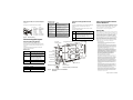
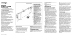
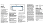
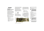
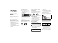
System Requirements Installing the Dialogic® Brooktrout® TruFax® BRI PCI Board Part Number: 931-107-05 The Dialogic® Brooktrout® TruFax® BRI (Basic Rate Interface ISDN) PCI boards are halfsized, single-slot PCI-bus compatible fax processing boards. They provide the following: On-board BRI connections Up to four V.17 fax channels per board The TruFax® BRI PCI Series boards can be used in either 3.3V or 5V bus (signaling) slots. You need a fax application to use a TruFax® BRI board. Dialogic does not provide the application or a driver for this board. A driver comes with the application that you purchase. This installation guide provides information about: System Requirements (including telephone service) Setting the Module Number Setting Termination Jumpers for the BRI Line Installing the Dialogic® Brooktrout® Board Recognizing PCI Slots Connecting the Phone Service Understanding LED Signals Using the Dialogic® Brooktrout® TruFax® BRI Board Getting Help This board must be installed in an enclosure that meets the following specifications: A Pentium or later host processor A PCI bus slot that runs at least 33 MHz and is 32 or 64 bits wide. See Recognizing PCI Slots for more information. Temperature: 0 C - 50 C Humidity: 10% - 95% (non-condensing) Power Requirements: Board Setting Termination Jumpers for the BRI Line Before installing your board, set termination for the BRI line if necessary. See Figure 5 for the location of the termination switches. Set jumpers as follows (See Figure 2 for details): 0A 0A 4.0 W Dual channel 0A 0A 4.5 W 0.9A 0A The following is also required: Telephone service: BRI interface Setting the Module Number Replace the cover. Turn on your computer. Note: Dialogic® Brooktrout® boards should not be present in the computer during the installation of any operating system. The operating system might misinterpret the board as being some other device, with unpredictable consequences. Recognizing PCI Slots The PCI connectors in the computer chassis usually appear as white slots. The TruFax® BRI board has a PCI board edge connector. It can be inserted into any of the PCI slots shown in Figure 3. +5 V +3.3 V +12 V -12 V Total Power Single channel 0.8A 0A 6. 7. Jumper is in place (ISDN BRI line is terminated) Jumper is removed (ISDN BRI line is not terminated) Universal PCI Board Edge Connector Figure 2. Termination Jumpers 3.3V 32-Bit Connector 5V 32-Bit Connector 3.3V 64-Bit Connector When the jumpers are removed from both switches for the appropriate port, there is no termination. When jumpers are present, the lines are terminated with 100 ohms (this is how the boards are shipped). Dialogic does not support any configuration except the two illustrated in Figure 2. Set each board to a unique module number to easily identify the resources associated with a specific board in a multi-board system. Use the SW-1 rotary switch (Figure 1) to set a unique module number for each Dialogic® Brooktrout® board. See Figure 5 for the switch location. Select a number from 2 - F on the rotary switch. Settings 0 and 1 are reserved and cannot be used. Installing the Dialogic® Brooktrout® Board To install your board: 1. Turn off your PC and remove the cover. Caution: A small amount of static electricity can destroy the sensitive components on your board. To prevent static damage, always connect yourself to ground using a ground strap before touching a circuit board. Handle boards only by the edges or metal mounting brackets and transport boards in an anti-static bag. Figure 1. Rotary Switch (SW-1) 2. 3. 4. 5. If the system has a PCI expansion hold-down bar, remove it. Locate a free PCI bus slot and remove the slot cover. Carefully align the board with the slot and firmly seat the board into the slot. Tighten the mounting bracket screw to secure the board to the chassis. Warning: When installing the board, be sure that the mounting bracket is securely fastened to the chassis and the chassis is plugged into a grounded three prong plug. Improper chassis or bracket grounding can result in harmful or fatal electrical shock as well as component damage. 5V 64-Bit Connector Insert the connector into any of these slots. Figure 3. PCI Slots Connecting the Phone Service The appropriate telephone service and hookups must be installed at your site in order to connect to telephone service. The following table shows the channel/port relationship: Channel Number 0 1 2 3 RJ-45 Port A A B B Type of Service BRI S/T BRI S/T BRI S/T BRI S/T Use the cable supplied with the board. Use these instructions to connect your board to BRI service: 1. Plug one end of the cable into the telephone connector on the board. Connect to Port A for channels 0 and 1 or to Port B for channels 2 and 3 (see Figure 5 to locate ports). 2. Plug the other end into the wall connector for your BRI service. Note: Port B is not present on the TruFax® BRI single port version. Before using your BRI service, you must configure certain parameters. See your LAN Fax documentation for details. See Figure 4 for pinout details for your board: Pin 1 2 3 4 5 6 7 8 Port A Port B No connection No connection TX Tip 0 RX Tip 0 RX Ring 0 TX Ring 0 No connection No connection No connection No connection TX Tip 1 RX Tip 1 RX Ring 1 TX Ring 1 No connection No connection Board Status LED Board Status LED Meaning Flashing yellow Board is powered up and is passing self test checks. Board is powered up, and the self test has failed. Board is powered up and is downloading firmware. Firmware is downloaded, and the board is in service. Board is hung, needs to be reset. Board has failed, needs to be reset. Board has no power, or board is hung and needs to be reset. Steady red Flashing yellow and green Flashing green Solid green Flickering red Off Figure 4. Connector Pinouts Understanding LED Signals LEDs on the Mounting Bracket Port A ISDN Termination Jumpers The LEDs on the mounting bracket provide information about the status of the different systems on the board. To identify and locate these LEDs, see Figure 5. LEDs on the Dialogic® Brooktrout® Board Using the Dialogic® Brooktrout® TruFax® BRI Board The LEDs on the board provide information about the status of the board. To locate these LEDs, see Figure 5. Once you have installed the TruFax® BRI board, install and configure your voice or fax software application according to instructions included with the software. After you have set up your software to support the board, your board provides support for your specific application. The following table describes how the LEDs on the board provide information: LED Meaning DSP Displays the status for the DSP. After the firmware is loaded and during normal execution, this LED blinks about every second. If the LED is not blinking, the DSP firmware is not running. Power Steady green indicates good board power. Module Number Switch (SW-1) Meaning Red Layer 1 is down. This can occur if the cable is wired incorrectly or the CPE or CO emulation is wrong. Layer 1 is up, but layer 2 is down. This state can occur if the protocol has not been initialized, the D channel has not been enabled, or the clocks have not synchronized. Layer 1 is up, and layer 2 is up. The board is currently receiving CRC errors. Yellow Green Red/green Channel LEDs Copyright © 2006-2008] Dialogic Corporation. All Rights Reserved. You may not reproduce this document in whole or in part without permission in writing from Dialogic Corporation at the address provided below. All contents of this document are subject to change without notice and do not represent a commitment on the part of Dialogic Corporation or its subsidiaries. Reasonable effort is made to ensure the accuracy of the information contained in the document. However, due to ongoing product improvements and revisions, Dialogic Corporation and its subsidiaries do not warrant the accuracy of this information and cannot accept responsibility for errors or omissions that may be contained in this document. Meaning Off Flashing green Channel is idle. Channel is being set up or is connected. INFORMATION IN THIS DOCUMENT IS PROVIDED IN CONNECTION WITH DIALOGIC® PRODUCTS. NO LICENSE, EXPRESS OR IMPLIED, BY ESTOPPEL OR OTHERWISE, TO ANY INTELLECTUAL PROPERTY RIGHTS IS GRANTED BY THIS DOCUMENT. EXCEPT AS EXPLICITLY SET FORTH BELOW OR AS PROVIDED IN A SIGNED AGREEMENT BETWEEN YOU AND DIALOGIC, DIALOGIC ASSUMES NO LIABILITY WHATSOEVER, AND DIALOGIC DISCLAIMS ANY EXPRESS OR IMPLIED WARRANTY, RELATING TO SALE AND/OR USE OF DIALOGIC PRODUCTS INCLUDING LIABILITY OR WARRANTIES RELATING TO FITNESS FOR A PARTICULAR PURPOSE, MERCHANTABILITY, OR INFRINGEMENT OF ANY INTELLECTUAL PROPERTY RIGHT OF A THIRD PARTY. Port A RJ-45 Connector Port B RJ-45 Connector Dialogic products are not intended for use in medical, life saving, life sustaining, critical control or safety systems, or in nuclear facility applications. BRI Status LEDs DSP LED - D7 Channel LEDs Board Status LED Mounting Bracket Channel LEDs Dialogic provides technical support for customers who have purchased hardware or software products from Dialogic. If you purchased products from a reseller, please contact that reseller for technical support. This equipment contains no user serviceable parts and is not intended for repair by unauthorized personnel. If you experience problems with the TruFax® BRI board, for repair or warranty information, please use the website below. If the equipment is causing harm to the telephone network, the telephone company might request that you disconnect the equipment until the problem is resolved. www.dialogic.com/support Copyright and Legal Notice The following tables describe how the end panel LEDs provide information: BRI Status LED BRI LED Getting Help PCI Connector Power LED - D10 Port B ISDN Termination Jumpers This graphic displays a Dual BRI board. Figure 5. Dialogic® Brooktrout® TruFax® BRI PCI Series Board It is possible that the use or implementation of any one of the concepts, applications, or ideas described in this document, in marketing collateral produced by or on web pages maintained by Dialogic Corporation or its subsidiaries may infringe one or more patents or other intellectual property rights owned by third parties. Dialogic Corporation or its subsidiaries do not provide any intellectual property licenses with the sale of Dialogic products other than a license to use such product in accordance with intellectual property owned or validly licensed by Dialogic Corporation or its subsidiaries. More detailed information about such intellectual property is available from Dialogic Corporation's legal department at 9800 Cavendish Blvd., 5th Floor, Montreal, Quebec, Canada H4M 2V9. The software referred to in this document is provided under a Software License Agreement. Refer to the Software License Agreement for complete details governing the use of the software. Dialogic Corporation encourages all users of its products to procure all necessary intellectual property licenses required to implement any concepts or applications and does not condone or encourage any intellectual property infringement and disclaims any responsibility related thereto. These intellectual property licenses may differ from country to country and it is the responsibility of those who develop the concepts or applications to be aware of and comply with different national license requirements. Dialogic, Dialogic Pro, Brooktrout, Cantata, SnowShore, Eicon, Eicon Networks, Eiconcard, Diva, SIPcontrol, Diva ISDN, TruFax, Realblocs, Realcomm 100, NetAccess, Instant ISDN, TRXStream, Exnet, Exnet Connect, EXS, ExchangePlus VSE, Switchkit, N20, Powering The Service-Ready Network, Vantage, Connecting People to Information, Connecting to Growth and Shiva, among others as well as related logos, are either registered trademarks or trademarks of Dialogic. Dialogic Corporation © 1998-2008