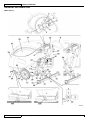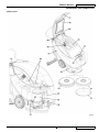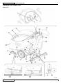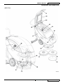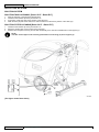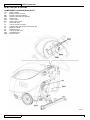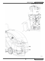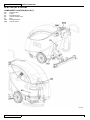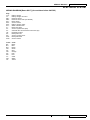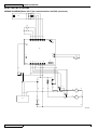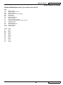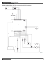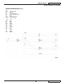
1
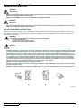
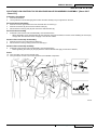
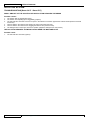
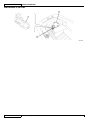
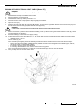
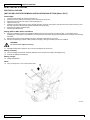
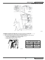
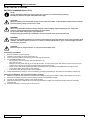
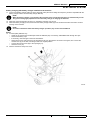
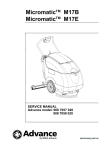
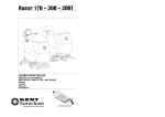
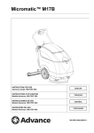
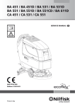
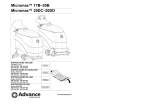
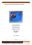
Razor SV17
Razor E17
SERVICE MANUAL
Kent models: 908 7113 020
908 7112 020
Simple. Clean.
909 6577 000(2)2007-06
ENGLISH
SERVICE MANUAL
909 6577 000(2)2007-06
Razor SV17 - Razor E17
SERVICE MANUAL
ENGLISH
TABLE OF CONTENTS
GENERAL INFORMATION . ....................................................................................................................................... 2
GENERAL INFORMATION .................................................................................................................................... 2
MACHINE LIFTING ................................................................................................................................................ 2
MACHINE TRANSPORTATION ............................................................................................................................. 2
OTHER REFERENCE MANUALS ......................................................................................................................... 2
SAFETY ................................................................................................................................................................. 3
GENERAL SAFETY PRECAUTIONS .................................................................................................................... 3
TECHNICAL DATA ................................................................................................................................................. 5
MAINTENANCE ..................................................................................................................................................... 6
SCHEDULED MAINTENANCE .............................................................................................................................. 6
SCHEDULED MAINTENANCE TABLE [Razor SV17] ........................................................................................... 6
SCHEDULED MAINTENANCE TABLE [Razor E17] .............................................................................................. 6
MACHINE NOMENCLATURE ................................................................................................................................ 7
SOLUTION SYSTEM ................................................................................................................................................ 12
SOLUTION TANK CLEANING [Razor SV17 - Razor E17] . ................................................................................. 12
SOLUTION FILTER CLEANING [Razor SV17 - Razor E17] . .............................................................................. 12
SOLUTION FLOW CONTROL TAP OR SOLENOID VALVE DISASSEMBLY/ASSEMBLY
[Razor SV17 - Razor E17] . .................................................................................................................................. 13
TROUBLESHOOTING [Razor SV17 - Razor E17] .............................................................................................. 14
BRUSHING SYSTEM ............................................................................................................................................... 15
BRUSH MOTOR ELECTRICAL INPUT CHECK [Razor SV17] . .......................................................................... 15
BRUSH MOTOR ELECTRICAL INPUT CHECK [Razor E17] .............................................................................. 17
BRUSH MOTOR CARBON BRUSH CHECK AND REPLACEMENT [Razor SV17] ............................................ 19
BRUSH MOTOR AND REDUCTION UNIT DISASSEMBLY/ASSEMBLY [Razor SV17] . .................................... 20
BRUSH MOTOR AND REDUCTION UNIT DISASSEMBLY/ASSEMBLY [Razor E17] ........................................ 21
TROUBLESHOOTING [Razor SV17] . ................................................................................................................. 22
TROUBLESHOOTING [Razor E17] ..................................................................................................................... 22
RECOVERY WATER SYSTEM ................................................................................................................................. 23
TANK AND VACUUM GRID WITH FLOAT CLEANING [Razor SV17 - Razor E17] ............................................. 23
VACUUM SYSTEM MOTOR ELECTRICAL INPUT CHECK [Razor SV17 - Razor E17] ..................................... 24
VACUUM SYSTEM MOTOR CARBON BRUSH CHECK AND REPLACEMENT
[Razor SV17 - Razor E17] . .................................................................................................................................. 26
VACUUM SYSTEM MOTOR DISASSEMBLY/ASSEMBLY [Razor SV17 - Razor E17] ....................................... 27
SQUEEGEE DISASSEMBLY/ASSEMBLY [Razor SV17 - Razor E17] ................................................................ 28
SQUEEGEE CLEANING/CHECK AND BLADE REPLACEMENT
[Razor SV17 - Razor E17] . .................................................................................................................................. 28
TROUBLESHOOTING [Razor SV17] . ................................................................................................................. 29
TROUBLESHOOTING [Razor SV17 - Razor E17] .............................................................................................. 29
OTHER SYSTEMS . .................................................................................................................................................. 30
MACHINE SPEED ADJUSTMENT [Razor SV17 - Razor E17] ............................................................................ 30
BRUSH/PAD-HOLDER DECK DISASSEMBLY/ASSEMBLY [Razor SV17] . ....................................................... 31
BRUSH/PAD-HOLDER DECK DISASSEMBLY/ASSEMBLY [Razor E17] ........................................................... 32
ELECTRICAL SYSTEM ............................................................................................................................................ 34
(WET OR GEL) BATTERY REMOVAL/INSTALLATION AND SETTING [Razor SV17] ....................................... 34
CHARGING CURVES SETTING [Razor SV17].................................................................................................... 35
BATTERY CHARGING [Razor SV17] .................................................................................................................. 36
ELECTRONIC BOARD REPLACEMENT [Razor SV17] ...................................................................................... 38
FUSE CHECK/REPLACEMENT [Razor SV17] .................................................................................................... 40
COMPONENT LOCATION [Razor SV17] ............................................................................................................ 42
COMPONENT LOCATION [Razor E17] ............................................................................................................... 44
WIRING DIAGRAM [Razor SV17] . ...................................................................................................................... 45
WIRING DIAGRAM [Razor E17] .......................................................................................................................... 46
Razor SV17 - Razor E17
909 6577 000(2)2007-06
ENGLISH
SERVICE MANUAL
GENERAL INFORMATION
GENERAL INFORMATION
NOTE
Forward and backward, front and rear, left and right are intended with reference to the operator’s position.
MACHINE LIFTING
WARNING!
Do not work under the lifted machine without supporting it with safety stands.
MACHINE TRANSPORTATION
WARNING!
Before transporting the machine, make sure that:
–
All doors and cases are closed
–
The battery connector, if present, is disconnected
–
The machine is securely fastened to the means of transport
OTHER REFERENCE MANUALS
The following manuals are available at Kent Literature Service Department:
Razor SV17 Instructions for Use - Form Number 909 5853 000
Razor SV17 Spare Parts List - Form Number 909 5854 000
Razor SV17 Installation Instruction for Battery charger kit- Form Number 9097050000
Razor SV17 - Razor E17 Installation Instructions for Curved squeegee kit - Form Number 909 6450 000
Razor SV17 - Razor E17 Installation Instructions for Rubber shock absorber kit - Form Number 909 6227 000
Razor E17 Instructions for Use - Form Number 909 5855 000
Razor E17 Spare Parts List - Form Number 909 5856 000
SAFETY
Kent uses the following symbols to indicate potentially dangerous situations. Always read this information carefully and take all
necessary precautions to safeguard people and property.
DANGER!
It indicates a dangerous situation with risk of death for the operator.
WARNING!
It indicates a potential risk of injury for people or damage to objects.
CAUTION!
It indicates a remark related to important or useful functions.
Pay particular attention to the paragraphs marked by this symbol.
NOTE
It indicates a caution or a remark related to important or useful functions.
CONSULTATION
It indicates the necessity to refer to the User Manual before performing any procedure.
GENERAL SAFETY PRECAUTIONS
Description of potential damages to people and machine.
DANGER!
[Razor SV17]
Disconnect the batteries before performing any maintenance/repair procedure.
–
This machine must be used by properly trained and authorized personnel only. Children or disabled people cannot
use this machine.
–
When using lead (WET) batteries, keep sparks, flames and incandescent materials away from the batteries. During
normal operation, explosive gases are released.
–
Do not wear jewerly when working near electrical components.
909 6577 000(2)2007-06
Razor SV17 - Razor E17
SERVICE MANUAL
ENGLISH
GENERAL INFORMATION
–
–
Do not operate the machine near toxic, dangerous, inflammable and/or explosive powders, fluids or vapors.
When using lead (WET) batteries, battery charging produces highly explosive hydrogen gas. During battery charging,
remove the recovery water tank and perform this procedure in well-ventilated areas and away from open flames.
DANGER!
[Razor E17]
–
–
–
–
–
–
–
–
–
–
–
–
–
–
–
–
–
–
–
–
–
–
–
–
–
–
–
–
–
–
–
–
–
–
–
–
–
Disconnect the cable from the electrical mains before performing any maintenance/repair procedure.
This machine must be used by properly trained and authorized personnel only. Children or disabled people cannot
use this machine.
Do not wear jewerly when working near electrical components.
Do not operate the machine near toxic, dangerous, inflammable and/or explosive powders, fluids or vapors.
WARNING!
[Razor SV17 - Razor E17]
Carefully read all the instructions before carrying out any maintenance/repair procedure.
To reduce the risk of fire, electric shock, or injury, do not leave the machine unattended when it is plugged in. Unplug
the machine from the outlet when not in use and before servicing.
To avoid electric shock, do not expose to rain. Store the machine indoors.
Do not allow to be used as a toy. Close attention is necessary when used near children.
Use only as described in this Manual. Use only Kent’s recommended accessories.
Do not use with damaged power supply cable or plug. If the machine is not working as it should, has been damaged,
left outdoors or dropped into water, return it to the Service Center.
If the supply cable or the plug is worn or damaged, it needs to be replaced by the Service Center.
Do not pull or carry the machine by the supply cable; never use the power supply cable as a handle. Do not close
a door on the supply cable, or pull the supply cable around sharp edges or corners. Do not run the machine on the
supply cable. Keep the supply cable away from heated surfaces.
Take all necessary precautions to prevent hair, jewerly and loose clothes from being caught in the machine moving or
vacuuming parts.
Do not work under the lifted machine without supporting it with safety stands.
Do not leave the machine unattended without being sure that the machine cannot move independently.
Do not use the machine on slopes with a gradient exceeding the specifications.
Do not wash the machine with direct or pressurized water jets, or with corrosive substances.
Do not use the machine in particularly dusty areas.
While using this machine, take care not to cause damage to people.
Do not put any can containing fluids on the machine.
The storage temperature must be between +32°F and +104°F (0°C and +40°C).
The machine working temperature must be between +32°F and +104°F (0°C and +40°C).
The humidity must be between 30% and 95%.
Always protect the machine against the sun, rain and bad weather, both under operation and inactivity condition.
Do not use the machine as a means of transport.
Do not use the machine on slopes with an inclination higher than 2%.
Do not allow the brush to operate while the machine is stationary to avoid damaging the floor.
In case of fire, possibly use a powder fire extinguisher, not a water one.
Do not bump into shelves or scaffoldings, particularly where there is a risk of falling objects.
Do not remove or modify the plates affixed to the machine.
If parts must be replaced, require ORIGINAL spare parts from a Dealer or Authorized Dealer.
The machine must be disposed of properly, because of the presence of toxic-harmful materials (plastic materials,
batteries, electronic boards, etc.), which are subject to standards that require disposal in special centers (see the
Instructions for Use Manual).
If the machine is used according to the instructions, the vibrations do not cause dangerous situations. The machine
vibration level is less than 98.42 in/s2 (2.5 m/s2) (98/37/EEC - EN 1033/1995).
This machine cannot be used on roads or public streets.
Pay attention during the machine transfers when temperature is below freezing point. The water in the recovery tank
or in the hoses could freeze and seriously damage the machine.
Use the brushes and the pads supplied with the machine and those specified in the Instructions for Use Manuals.
Using other brushes or pads could reduce safety.
When lead (WET) batteries are installed on the machine, do not tilt the machine more than 30° from the horizontal
plane to prevent the highly corrosive acid from leaking out of the batteries. If the machine must be tilted to perform
any maintenance procedure, remove the batteries.
Razor SV17 - Razor E17
909 6577 000(2)2007-06
ENGLISH
SERVICE MANUAL
GENERAL INFORMATION
WARNING!
[Razor SV17]
–
–
Before connecting the battery charger to the electrical mains, be sure that frequency and voltage indicated in the
Manual are compatible with the mains voltage.
When using lead (WET) batteries, do not smoke while charging the batteries.
WARNING!
[Razor E17]
–
Before connecting the machine to the electrical mains, make sure that the frequency and voltage shown on the serial
plate (7) are compatible with the mains voltage.
120 VAC GROUNDING INSTRUCTIONS
This appliance must be grounded. If it should electrically malfunction, grounding provides a path of least resistance for electric
current to reduce the risk of electric shock. This appliance is equipped with a cord having an equipment-grounding conductor and
grounding plug. The plug must be plugged into an appropriate outlet that is properly installed and grounded in accordance with all
local codes and ordinances.
WARNING!
The machine must be used with an extension power cord as follows:
–
minimum length 15 feet
–
type S, or ST, or SO, or STO, or STW
–
minimum rate 300V 140/167°F (60/75°C)
DANGER!
–
–
–
–
–
Improper connection of the equipment-grounding conductor can result in a risk of electric shock. Check with a
qualified electrician or service person if you are in doubt as to whether the outlet is properly grounded. Do not modify
the plug provided with the appliance. If it will not fit the outlet, have a proper outlet installed by a qualified electrician.
This appliance is for use on a nominal 120 V circuit, and has a grounding plug that looks like the plug (B, Fig. 1). A
temporary adapter (B and C) may be used to connect this plug to a 2-pole receptacle (B), if a properly grounded outlet
is not available. The temporary adapter should be used only until a properly grounded outlet (A) can be installed by
a qualified electrician. The green-colored rigid ear, tab, or the like extending from the adapter must be connected to
a permanent ground such as a properly grounded outlet box cover. Whenever the adapter is used, it must be held in
place by a metal screw. Grounding adapters are not approved for use in Canada.
Replace the plug if the grounding pin is damaged or broken.
The Green (or Green/Yellow) wire in the cord is the grounding wire. When replacing a plug, this wire must be attached
to the grounding pin only.
Extension cords connected to this machine should be 12 gauge, three-wire cords with three-prong plugs and outlets.
DO NOT use extension cords more than 50 feet (15 m) long.
A
B
C
S310183A
909 6577 000(2)2007-06
Razor SV17 - Razor E17
SERVICE MANUAL
ENGLISH
GENERAL INFORMATION
TECHNICAL DATA
General
Razor SV17
Razor E17
Cleaning width
16.9 in (430 mm)
Machine width (without squeegee)
22.4 in (570 mm)
Minimum machine length with adjustable handlebar
36.6 in (930 mm)
Minimum machine height with adjustable handlebar
44.1 - 44.7 in (1120 - 1135 mm)
Squeegee width with straight squeegee (standard)
28.3 in (720 mm)
Squeegee width with curved squeegee (optional)
30 in (760 mm)
Minimum turning radius
29.5 in (750 mm)
Machine net weight
158.4 lb (72 Kg)
165 lb (75 Kg)
Machine weight in running condition (with batteries, battery charger and
brush)
282.2 lb (128 Kg)
-
Battery compartment size
13.8x13.8x10.2 in
350x350x260 mm
-
-
194 lb (88 Kg)
Machine weight in running condition (with brush)
Central (fixed axle) wheel diameter
9.8 in (250 mm)
Brush/pad diameter
17.0 in (430 mm)
Max pressure wheel on the ground (*)
< 52.2 psi (0.36 N/mm2)
< 33.3 psi (0.23 N/mm2)
50.6 lbs (23 Kg)
62.2 lb (28 Kg)
Brush/pad pressure on the ground (with full tank)
(*) the machines is tested in the following conditions:
• max size battery
• max size brush deck / squeegee
• solution tank full
• optionals installed
• weight verified on each wheel
• print area verified on concrete for each wheel
• result expresses as max. value for front and max value for rear wheels
Performance
Razor SV17
Razor E17
41.5 in H2O (1,055 mm H2O)
51.8 in H2O (1,316 mm H2O)
67 dB(A)
76 dB(A)
Vacuum system motor power
300 W
550 W 60 Hz
Brush/pad motor power
520 W
550 W 60 Hz
135 rpm
170 rpm
Battery voltage
24 V
-
System voltage
-
115 V
12 V, 50 Ah
-
Vacuum
Sound pressure level
Brush/pad holder motor speed
Standard batteries
Clean water tank capacity
8.1 gal (31 liters)
Recovery water tank capacity
7.9 gal (30 liters)
Solution flow (min/max)
0.08-0.26 gallons/min (0.3-1 liters/min)
Razor SV17 - Razor E17
909 6577 000(2)2007-06
SERVICE MANUAL
ENGLISH
GENERAL INFORMATION
MAINTENANCE
SCHEDULED MAINTENANCE
The lifespan of the machine and its maximum operating safety are ensured by correct and regular maintenance.
See the GENERAL INFORMATION and SAFETY paragraphs.
Provided below is the Scheduled Maintenance Table. The intervals shown may vary according to particular working conditions,
which are to be defined by the person in charge of the maintenance.
For instructions on maintenance procedures, see the following paragraphs.
SCHEDULED MAINTENANCE TABLE [Razor SV17]
Daily or after
using the
machine
Procedure
Weekly
Every six
months
Yearly
Squeegee cleaning
Brush cleaning
Tank and vacuum grid with float cleaning
Battery charging
Squeegee blade check (and replacement)
Solution filter cleaning
Battery (WET) fluid level check
Screw and nut tightening check
(1)
Brush motor carbon brush check or replacement
Vacuum system motor carbon brush check or replacement
(1): and after the first 8 working hours
SCHEDULED MAINTENANCE TABLE [Razor E17]
Procedure
Daily or after
using the
machine
Weekly
Every six
months
Squeegee cleaning
Brush cleaning
Tank and vacuum grid with float cleaning
Squeegee blade check (and replacement)
Solution filter cleaning
Screw and nut tightening check
(1)
Vacuum system motor carbon brush check or replacement
(1): and after the first 8 working hours
909 6577 000(2)2007-06
Razor SV17 - Razor E17
Yearly
SERVICE MANUAL
ENGLISH
GENERAL INFORMATION
MACHINE NOMENCLATURE
In this Manual, numbers in brackets – for example: (2) - refer to the components shown in the nomenclature pages. Refer to these
pages whenever it is necessary to identify a component mentioned in the text.
1. Control panel
2. [S] Charged battery warning light (green)
3. [S] Half-discharged battery warning light (yellow)
4. [S] Discharged battery warning light (red)
5. Brush/pad switch
6. Vacuum switch
7. Serial number plate/technical data
8. Handlebar
9. Handlebar inclination adjusting knob
10. Solution flow control lever
11a.Solution flow control lever ECO position (water “economy”
usage, for a washing autonomy of 70-80 minutes).
11b.Maximum solution flow
12. Recovery water tank cover
13. Rear support wheel for transport/parking
14. Central wheels on fixed axle
15. Brush/pad-holder with pad
16. Brush/pad-holder deck
17. Squeegee
18. Squeegee fixing handwheels
19. Front squeegee blade
20. Rear squeegee blade
21. Squeegee blade fixing springs
22. Recovery water drain hose
23. Recovery water drain hose bracket
24. Solution drain valve
25. Squeegee lifting/lowering lever
26. Solution filter
27. [S] Battery charger-electrical mains connecting cable
(optional)
28. [E] Power supply cable
29. Squeegee vacuum hose
30. Transport/parking device
30a.Transport/parking device activated
30b.Transport/parking device deactivated
31. Locking pin for transport/parking device
32. [S] Electrical component box
33.
34.
35.
36.
37.
38.
39.
40.
41.
42.
43.
44.
45.
46.
47.
48.
49.
50.
51.
52.
53.
54.
55.
56.
57.
58.
59.
60.
[S] Battery charger
[S] Battery charger warning lights
[S] Warning label
[S] Battery connector (models without on-board battery
charger)
Brush/pad-holder support
Recovery water tank
Solution tank
Compensation hole
Recovery water tank cover (open)
Recovery water tank cover gasket
Recovery water tank
Solution tank
Brush/pad-holder support (activated)
Vacuum grid with automatic shut-off float
Recovery water drain hole
Vacuum motor
Brush/pad-holder motor
[S] Batteries
[S] Battery installation diagram
Brush/pad-holder deck
Machine speed adjustment screw
Brush
Pad-holder
Pad
Right deck fastening screw
Left deck fastening screws
[E] Terminal board box
Cover stand (applied)
[S]:
[E]:
Razor SV17 - Razor E17
Installed on Razor SV17
Installed Razor E17
909 6577 000(2)2007-06
ENGLISH
SERVICE MANUAL
GENERAL INFORMATION
[Razor SV17]
35
S301386
909 6577 000(2)2007-06
Razor SV17 - Razor E17
SERVICE MANUAL
ENGLISH
GENERAL INFORMATION
[Razor SV17]
S301387
Razor SV17 - Razor E17
909 6577 000(2)2007-06
ENGLISH
SERVICE MANUAL
GENERAL INFORMATION
[Razor E17]
S301388
10
909 6577 000(2)2007-06
Razor SV17 - Razor E17
SERVICE MANUAL
ENGLISH
GENERAL INFORMATION
[Razor E17]
S301389
Razor SV17 - Razor E17
909 6577 000(2)2007-06
11
ENGLISH
SERVICE MANUAL
SOLUTION SYSTEM
SOLUTION SYSTEM
SOLUTION TANK CLEANING [Razor SV17 - Razor E17]
1.
2.
3.
4.
Drive the machine to the appointed disposal area.
Check that the switches (5 and 6) are turned to “0”.
If necessary, empty the tank (44) by means of the valve (24).
Wash the tank (44) with clean water, then drain the water from the tank by means of the valve (24).
SOLUTION FILTER CLEANING [Razor SV17 - Razor E17]
1.
2.
3.
Check that the switches (5 and 6) are turned to “0”.
Empty the solution tank (44) by means of the valve (24).
Remove the transparent cover (A) and the filter strainer (B), then clean and reinstall them on the support (C).
NOTE
The filter strainer (B) must be correctly positioned on the housing (C) of the support (C).
S301390
[The figure shows Razor SV17]
12
909 6577 000(2)2007-06
Razor SV17 - Razor E17
SERVICE MANUAL
ENGLISH
SOLUTION SYSTEM
SOLUTION FLOW CONTROL TAP OR SOLENOID VALVE DISASSEMBLY/ASSEMBLY [Razor SV17
- Razor E17]
Preliminary procedures
1.
2.
Remove the batteries.
Use a protection to avoid damaging the machine and tilt it carefully to lay its right side on the floor.
Solenoid valve disassembly
3.
4.
5.
Remove the screw (B) and disconnect the solenoid valve connector (C).
Remove the screws (D) and move the solenoid valve (E).
Disconnect the hoses (F) and (G) and recover the solenoid valve (E).
Solenoid valve assembly
6.
Assemble in the reverse order of disassembly, and note these items:
• When assembling a new solenoid valve (E), the stamping must point outwards; moreover, before installing the unions (M)
and (N) clean the relevant threads and apply LOCTITE 572 sealant.
Solution flow control tap disassembly
7.
8.
Remove the four nuts (H) and the two clamps (I).
Disconnect the hoses (J) and (K) and recover the tap (L).
Solution flow control tap assembly
9.
Assemble in the reverse order of disassembly, and note these items:
• before tightening the unions (O) and (P) clean the relevant threads and apply LOCTITE 572 sealant.
Reset
10. Carry out steps 1 and 2 in the reverse order.
11. Carry out hands-on tests to check the operation of the installed components.
E
B
E
J
L
C
G
D
N
M
H
F
I
K
O
L
P
S301209
Razor SV17 - Razor E17
909 6577 000(2)2007-06
13
ENGLISH
SERVICE MANUAL
SOLUTION SYSTEM
TROUBLESHOOTING [Razor SV17 - Razor E17]
SMALL AMOUNT OF THE SOLUTION OR NO SOLUTION REACHES THE BRUSH
Possible causes:
1.
2.
3.
4.
5.
6.
The solution filter is clogged/dirty (clean).
The solution flow adjusting tap is clogged/dirty (replace).
The solenoid valve is broken or there is an open in the electrical connection (replace the solenoid valve/repair the electrical
connection).
There is debris in the solution tank clogging the output hole (clean the tank).
There is debris in the solution hose clogging the solution flow (clean the hose).
The detergent flow control tap is in the ECO position (adjust the detergent flow control lever)
THE SOLUTION REACHES THE BRUSH ALSO WHEN THE MACHINE IS OFF
Possible cause:
1.
The solenoid valve is broken (replace).
14
909 6577 000(2)2007-06
Razor SV17 - Razor E17
SERVICE MANUAL
ENGLISH
BRUSHING SYSTEM
BRUSHING SYSTEM
BRUSH MOTOR ELECTRICAL INPUT CHECK [Razor SV17]
WARNING!
This procedure must be performed by qualified personnel only.
1.
2.
3.
4.
5.
6.
7.
Check that the brush (54) is installed on the machine.
Drive the machine on a level ground.
Check that the switches (5 and 6) are turned to “0”.
If there is recovery water in the tank (43), drain it through the hose (22).
Disconnect the vacuum hose (29) from the squeegee (17).
Open the cover (12).
Grasp the recovery water tank (A) in the area (B) and lift it, as shown in the figure, then disconnect the vacuum hose (C) from
the tank and remove the tank (A) together with the hoses (D) and (E).
WARNING!
Do not touch uncovered electrical components while performing the following steps.
8.
9.
Set an ammeter (F) on the battery supply cable (red) (G) of the brush motor (H). Adjust the full-scale at 50 A or more.
Activate the brush by turning the switch (5) to “I”, then check that the brush motor electrical input is within the following limits:
• with the brush on floor tiles: 8 to 10 A
• with lifted brush: 2,7 to 3,2 A
Turn the switch (5) to “0”.
If the electrical input is higher, perform the following procedures to detect and eliminate the cause of the abnormal input:
• Remove from the brush rotation shaft/flange all the possible amounts of dirt or wrapped-round materials (ropes, clothes,
etc.), which prevent or slow down its rotation;
• If necessary, check the motor carbon brushes;
• If necessary, disassemble the motor, clean it and check its moving parts.
If the above-mentioned procedures do not lead to a correct electrical input, the motor must be replaced.
10. Carry out steps from 5 to 8 in the reverse order.
S301369
Razor SV17 - Razor E17
909 6577 000(2)2007-06
15
ENGLISH
SERVICE MANUAL
BRUSHING SYSTEM
S301370
16
909 6577 000(2)2007-06
Razor SV17 - Razor E17
SERVICE MANUAL
ENGLISH
BRUSHING SYSTEM
BRUSH MOTOR ELECTRICAL INPUT CHECK [Razor E17]
WARNING!
This procedure must be performed by qualified personnel only.
1.
2.
3.
4.
5.
6.
7.
Check that the brush (A) is installed on the machine.
Drive the machine on a level ground.
Check that the switches (5 and 6) are turned to “0”.
If there is recovery water in the tank (43), drain it through the hose (22).
Disconnect the vacuum hose (29) from the squeegee (17).
Open the cover (12).
Grasp the recovery water tank (A) in the area (B) and lift it, as shown in the figure, then disconnect the vacuum hose (C) from
the tank and remove the tank (A) together with the hoses (D) and (E).
WARNING!
Do not touch uncovered electrical components while performing the following steps.
8.
Remove the screws (F) and the terminal board box sealing cover (G). When installing the terminal board box cover (G), check
for gasket integrity and efficiency.
9. Set an ammeter (H) on the brush motor supply cable (I).
10. Activate the brush by turning the switch (5) to “I”, then check that the brush motor electrical input is within the following limits:
• with the brush on floor tiles: 6 to 8 A
• with lifted brush: 5.5 to 6 A
Turn the switch (5) to “0”.
If the electrical input is higher, perform the following procedures to detect and eliminate the cause of the abnormal input:
• Remove from the brush rotation shaft/flange all the possible amounts of dirt or wrapped-round materials (ropes, clothes,
etc.), which prevent or slow down its rotation;
• If necessary, check the motor carbon brushes;
• If necessary, disassemble the motor, clean it and check its moving parts.
If the above-mentioned procedures do not lead to a correct electrical input, the motor must be replaced.
11. Carry out steps from 5 to 9 in the reverse order.
S301369
Razor SV17 - Razor E17
909 6577 000(2)2007-06
17
ENGLISH
SERVICE MANUAL
BRUSHING SYSTEM
S301371
BRUSH MOTOR CARBON BRUSH CHECK AND REPLACEMENT [Razor SV17] (for machines before
2007/05)
1.
2.
3.
4.
5.
6.
Remove the brush/pad-holder deck (see the procedure in the relevant paragraph).
At the workbench, remove dust and dirt from the outside of the motor, then disengage and remove the clamp (A).
Lift the retaining spring (B) of each carbon brush, then remove the four carbon brushes (C).
Check if the four carbon brushes are worn out. Replace the carbon brushes when: the contact with the motor armature is
insufficient, the carbon brushes are worn, the carbon brush contact surface is not integral, the thrust spring is broken, etc.
If necessary, remove the nuts (D) and disengage the lead-in wires (E), then remove the carbon brushes.
Replace the carbon brushes as an assembly.
Assemble in the reverse order of disassembly, and note these items:
• When connecting the terminals (E), take care of their insulation from the surrounding parts of the frame.
S300310
18
909 6577 000(2)2007-06
Razor SV17 - Razor E17
SERVICE MANUAL
ENGLISH
BRUSHING SYSTEM
BRUSH MOTOR CARBON BRUSH CHECK AND REPLACEMENT [Razor SV17] (for machines after
2007/05)
1.
2.
3.
4.
5.
6.
Remove the brush/pad-holder deck (see the procedure in the relevant paragraph).
At the workbench, remove dust and debris from the motor, especially in the area of the carbon brushes.
Remove four protection covers (A) by disengaging the fasteners.
Remove the carbon brush nuts (B) with the lead-in wires.
Disengage the tabs (C) and remove the carbon brushes (D).
Check if the carbon brushes (D) are worn. Replace the carbon brushes when: the contact with the motor armature is
insufficient, the carbon brushes are worn, the carbon brush contact surface is not integral, the thrust spring is broken, etc.
Replace the carbon brushes as an assembly.
Reset
7.
Assemble the components in the reverse order of disassembly.
A
A
B
D
C
C
S301543
Razor SV17 - Razor E17
909 6577 000(2)2007-06
19
SERVICE MANUAL
ENGLISH
BRUSHING SYSTEM
BRUSH MOTOR AND REDUCTION UNIT DISASSEMBLY/ASSEMBLY [Razor SV17]
Motor/reduction unit disassembly/assembly
1.
2.
3.
4.
5.
6.
7.
8.
Remove the brush/pad-holder (54/55), according to the instructions in the Instructions for Use Manual.
Remove the brush/pad-holder deck.
At the workbench, remove the central screw (A).
Remove the polygonal support (B).
Recover the key (C).
Remove the screws (D).
Remove the brush motor (E).
Assemble in the reverse order of disassembly.
Separating the motor from the reduction unit
9. Disassemble the motor/reduction unit as above indicated.
10. Remove the nuts (F) fixing the motor to the reduction unit.
11. Carefully lift and remove the motor (E) together with the pinion and bearing.
CAUTION!
To prevent part (H) and part (I) from separating during the motor disassembly/assembly, it is advisable to apply
adhesive tape temporarily to keep the two parts together.
12. Recover the reduction unit and the oil (J).
13. Assemble in the reverse order of disassembly, and note these items:
• Before installing the new reduction unit, fill in with oil of the type and quantity indicated on the reduction unit data plate
(SAE W 80 - 90 oil). The oil in the tank must cover the gear (K).
• Remember to remove the adhesive tape, if applied at step 11.
F
E
H
I
G
J
D
D
C
B
A
S301213
20
909 6577 000(2)2007-06
Razor SV17 - Razor E17
SERVICE MANUAL
ENGLISH
BRUSHING SYSTEM
BRUSH MOTOR AND REDUCTION UNIT DISASSEMBLY/ASSEMBLY [Razor E17]
Motor/reduction unit disassembly/assembly
1.
2.
3.
4.
5.
6.
7.
8.
Remove the brush/pad-holder (54/55), according to the instructions in the Instructions for Use Manual.
Remove the brush/pad-holder deck.
At the workbench, remove the central screw (A).
Remove the polygonal support (B).
Recover the key (C).
Remove the screws (D).
Remove the brush motor (E).
Assemble in the reverse order of disassembly.
Separating the motor from the reduction unit
9.
10.
11.
12.
13.
Disassemble the motor/reduction unit as above indicated.
Remove the nuts (F) fixing the motor to the reduction unit.
Carefully lift and remove the motor (E) together with the pinion and bearing.
Recover the reduction unit and the oil (J).
Assemble in the reverse order of disassembly, and note these items:
• Before installing the new reduction unit, fill in with oil of the type and quantity indicated on the reduction unit data plate
(SAE W 80 - 90 oil). The oil in the tank must cover the gear (K).
E
G
F
J
D
D
C
B
A
S301214
Razor SV17 - Razor E17
909 6577 000(2)2007-06
21
ENGLISH
SERVICE MANUAL
BRUSHING SYSTEM
TROUBLESHOOTING [Razor SV17]
OPEN CIRCUIT
The brush motor fuse F1 determines the open circuit. This system allows to prevent the brush motor and circuits from being
damaged under overload conditions.
If there is an open in the circuit, the possible causes are:
1. Bulky debris or cords around the brush or between the brush and its flange (remove the brush and the debris or cords).
2. The brush motor electrical input is too high (check the electrical input).
THE BRUSH DOES NOT ROTATE
Possible causes:
1.
2.
3.
4.
5.
6.
7.
8.
The battery voltage is too low (charge the battery).
The motor carbon brushes are worn (replace).
The motor is faulty (repair or replace).
The brush motor fuse is burned (solve the problem and replace the fuse).
The brush ON/OFF switch (5) is broken (replace).
The reduction unit is faulty (repair or replace).
The wiring harness is damaged (repair).
The brush electromagnetic switch is damaged (replace).
TROUBLESHOOTING [Razor E17]
THE BRUSH DOES NOT ROTATE
Possible causes:
1.
2.
3.
4.
5.
The power supply cable is broken (replace).
The motor is faulty (repair or replace).
The brush ON/OFF switch (5) is broken (replace).
The reduction unit is faulty (repair or replace).
The wiring harness is damaged (repair).
22
909 6577 000(2)2007-06
Razor SV17 - Razor E17
SERVICE MANUAL
ENGLISH
RECOVERY WATER SYSTEM
RECOVERY WATER SYSTEM
TANK AND VACUUM GRID WITH FLOAT CLEANING [Razor SV17 - Razor E17]
1.
2.
3.
4.
5.
6.
Drive the machine to the appointed disposal area.
Check that the switches (5 and 6) are turned to “0”.
If necessary, empty the tank (43) by means of the hose (22).
Lift the cover (41), then wash with clean water the cover, the tank (43) and the vacuum grid (46).
Drain the water in the tank through the hose (22).
If necessary, release the fasteners (A) and open the grid (B), recover the float (C), clean all the components and then reinstall
them.
Check the recovery water tank cover gasket (D) for integrity.
NOTE
The gasket (D) creates vacuum in the tank that is necessary for vacuuming the recovery water.
7.
8.
If necessary replace the gasket (D) after removing it from its housing (E).
When assembling the new gasket, install its joint (F) in the central area, as shown in the figure.
Check the gasket (G) bearing surface (D) for integrity and sealing capabilities.
Check the compensation hole (H) for clogging.
NOTE
The hole (H) compensates the air in the cover interspaces, thus allowing the creation of vacuum in the recovery
water tank.
9.
Close the cover (41).
S301372
Razor SV17 - Razor E17
909 6577 000(2)2007-06
23
ENGLISH
SERVICE MANUAL
RECOVERY WATER SYSTEM
VACUUM SYSTEM MOTOR ELECTRICAL INPUT CHECK [Razor SV17 - Razor E17]
WARNING!
This procedure must be performed by qualified personnel only.
1.
2.
3.
4.
5.
6.
Drive the machine on a level ground.
Check that the switches (5 and 6) are turned to “0”.
If there is recovery water in the tank (43), drain it through the hose (22).
Disconnect the vacuum hose (29) from the squeegee (17).
Open the cover (12).
Grasp the recovery water tank (A) in the area (B) and lift it, as shown in the figure, then disconnect the vacuum hose (C) from
the tank and remove the tank (A) together with the hoses (D) and (E).
(Razor E17) Loosen the clamp (I) and disconnect the hoses (J), then remove the waterproof cover (K).
WARNING!
Do not touch uncovered electrical components while performing the following steps.
7.
8.
Place an ammeter (F) on one of the cables (G) of the vacuum system motor (H).
Activate the vacuum system by turning the switch (6) to “I”, then check that the vacuum system motor electrical input is within
the following limits:
Razor SV17:
• - 14 to 17 A
Razor E17:
• - 4 to 4.5 A
Turn the switch (6) to “0”.
If the electrical input is higher, perform the following procedures to detect and eliminate the cause of the abnormal input:
• Check the motor carbon brushes;
• If necessary, disassemble the motor and clean it carefully, then check the condition of its moving parts.
• If the above-mentioned procedures do not lead to a correct electrical input, the motor must be replaced.
Carry out steps from 4 to 8 in the reverse order.
9.
S301369
24
909 6577 000(2)2007-06
Razor SV17 - Razor E17
SERVICE MANUAL
ENGLISH
RECOVERY WATER SYSTEM
S301373
[The figure shows Razor SV17]
Razor SV17 - Razor E17
909 6577 000(2)2007-06
25
ENGLISH
SERVICE MANUAL
RECOVERY WATER SYSTEM
VACUUM SYSTEM MOTOR CARBON BRUSH CHECK AND REPLACEMENT [Razor SV17 - Razor E17]
1.
2.
3.
4.
5.
6.
7.
Remove the vacuum system motor (see the procedure in the relevant paragraph).
At the workbench, disengage the fasteners (A) and (B), then remove the cover (C) from the vacuum system motor.
Remove the screws (D) and the fasteners (E).
Disconnect the electrical connections (F) and remove the brushes (G).
Check the carbon brushes for wear. Replace the carbon brushes when: the contact with the motor armature is insufficient, the
carbon brushes are worn, the carbon brush contact surface is not integral, the thrust spring is broken, etc.
If necessary, replace the carbon brushes. Replace the carbon brushes as an assembly.
Assemble in the reverse order of disassembly.
S301231
26
909 6577 000(2)2007-06
Razor SV17 - Razor E17
SERVICE MANUAL
ENGLISH
RECOVERY WATER SYSTEM
VACUUM SYSTEM MOTOR DISASSEMBLY/ASSEMBLY [Razor SV17 - Razor E17]
1.
2.
3.
4.
5.
Check that the switches (5 and 6) are turned to “0”.
If there is recovery water in the tank (43), drain it through the hose (22).
Disconnect the vacuum hose (29) from the squeegee (17).
Open the cover (12).
Grasp the recovery water tank (A) in the area (B) and lift it, as shown in the figure, then disconnect the vacuum hose (C) from
the tank and remove the tank (A) together with the hoses (D) and (E).
6. (Razor E17) Loosen the clamp (I) and disconnect the hoses (J), then remove the waterproof cover (K).
7. Disconnect the vacuum system motor electrical connector (F).
8. Remove the vacuum system motor fastening screws (G).
9. Remove the vacuum system motor (H).
10. Assemble in the reverse order of disassembly.
S301369
S301374
S301375
Razor SV17 - Razor E17
909 6577 000(2)2007-06
27
SERVICE MANUAL
ENGLISH
RECOVERY WATER SYSTEM
SQUEEGEE DISASSEMBLY/ASSEMBLY [Razor SV17 - Razor E17]
1.
2.
3.
4.
5.
Check that the switches (5 and 6) are turned to “0”.
Lower the squeegee (17) by means of the lever (25).
Disconnect the vacuum hose (29) from the squeegee.
Loosen the handwheels (18) and remove the squeegee (17).
Assemble in the reverse order of disassembly.
SQUEEGEE CLEANING/CHECK AND BLADE REPLACEMENT [Razor SV17 - Razor E17]
CAUTION!
It is advisable to use protective gloves when cleaning the squeegee because there may be cutting debris.
Preliminary procedures
1.
Remove the squeegee.
Cleaning
2.
Wash and clean the squeegee; in particular, clean the compartments (A) and the vacuum hole (B) from dirt and debris.
Check the front blade (C) and the rear blade (D) for integrity, cuts and tears; otherwise replace them.
Blade check and overturning/replacement
3.
4.
Check that the edges (E) of the front blade and the edges (F) of the rear blade lay down on the same level, along their length;
otherwise adjust their height according to the following procedure:
• Remove the fixing springs (G) and adjust the front blade (C) and the rear blade (D). Reinstall the fixing springs on the
properly adjusted front and rear blades.
Check the front blade (C) and rear blade (D) for integrity, cuts and tears; otherwise replace them according to the following
procedure. Also check the front corner (H) of the rear blade for wear; if it is worn, overturn the blade to replace the worn corner
with the other one (I), provided that it is integral. If the other corner (I) is worn too, replace the blade according to the following
procedure:
• Remove the fixing springs (G) and replace (or overturn) the rear blade (D). Reinstall the fixing springs on the properly
adjusted front and rear blades, according to the procedure shown in the previous step.
Reset
5.
Assemble the squeegee.
D
C
A
B
G
A
E
H
F
I
G
S301218
28
909 6577 000(2)2007-06
Razor SV17 - Razor E17
SERVICE MANUAL
ENGLISH
RECOVERY WATER SYSTEM
TROUBLESHOOTING [Razor SV17]
OPEN CIRCUIT
The vacuum system motor fuse 1 determines the open circuit. This system allows to prevent the vacuum system motor and its
circuits from being damaged under overload conditions.
If there is an open in the circuit, the possible causes are:
1. The motor is damaged (check the motor carbon brushes/electrical input).
2. The electrical input is excessive (check the motor for proper rotation).
TROUBLESHOOTING [Razor SV17 - Razor E17]
DIRTY WATER VACUUMING IS INSUFFICIENT OR THERE IS NO VACUUMING
Possible causes:
1.
The vacuum grid with automatic shut-off float (46) is activated because the water recovery tank (43) is full (empty the water
recovery tank).
2. The grid (46) is dirty (clean).
3. The recovery water tank cover (12) is not correctly positioned (adjust).
4. The tank cover gasket (42) is not efficient or the compensating hole is clogged (solve the problems).
5. The squeegee or the vacuum hose is clogged or damaged (clean or repair/replace).
6. The vacuum system motor carbon brushes are worn (replace).
7. The vacuum system motor is faulty (repair or replace).
8. The vacuum ON/OFF switch (6) is broken (replace).
9. The wiring harness is damaged (repair).
10. The vacuum system motor electromagnetic switch is broken (replace).
THE SQUEEGEE LEAVES LINING ON THE FLOOR OR DOES NOT COLLECT WATER
Possible causes:
1.
2.
3.
There is debris under the squeegee lip (remove).
The squeegee blades are torn or worn (replace).
The squeegee front and rear blade are not aligned (align).
Razor SV17 - Razor E17
909 6577 000(2)2007-06
29
ENGLISH
SERVICE MANUAL
OTHER SYSTEMS
OTHER SYSTEMS
MACHINE SPEED ADJUSTMENT [Razor SV17 - Razor E17]
1.
2.
3.
4.
5.
6.
7.
8.
Check that the switches (5 and 6) are turned to “0”.
If there is recovery water in the tank (43), drain it through the hose (22).
Disconnect the vacuum hose (29) from the squeegee (17).
Open the cover (12).
Grasp the recovery water tank (A) in the area (B) and lift it, as shown in the figure, then disconnect the vacuum hose (C) from
the tank and remove the tank (A) together with the hoses (D) and (E).
Adjust the machine speed by means of the screw (53), according to the following procedure:
• Loosen the screw (57) on the right side of the machine, by turning it counter-clockwise.
• Turn the adjusting screw (53) counter-clockwise to increase the machine speed.
• Turn the adjusting screw (53) clockwise to decrease the machine speed.
• After adjusting, tighten the screw (57).
Carry out steps from 3 to 5 in the reverse order.
With the machine ready to operate, carry out hands-on tests of the machine speed and, if other adjustments are necessary,
repeat steps 1 to 8.
S301369
30
909 6577 000(2)2007-06
Razor SV17 - Razor E17
SERVICE MANUAL
ENGLISH
OTHER SYSTEMS
BRUSH/PAD-HOLDER DECK DISASSEMBLY/ASSEMBLY [Razor SV17]
Disassembly
1.
2.
3.
4.
5.
6.
7.
Remove the batteries.
Remove the caps (A) and disconnect the electrical connections from the brush motor (B).
Remove the left deck fastening screw (58).
Use a protection (D) to avoid damaging the machine and tilt it carefully to lay its left side on the floor.
Disconnect the solution hose (E) from the solenoid valve (F).
Remove the right deck fastening screw (57).
Remove the deck (H).
Assembly
8.
Assemble in the reverse order of disassembly, and note these items:
• When reassembling the deck (H), reinsert the deck fixing springs (I) correctly.
S301376
S301220
Razor SV17 - Razor E17
909 6577 000(2)2007-06
31
ENGLISH
SERVICE MANUAL
OTHER SYSTEMS
BRUSH/PAD-HOLDER DECK DISASSEMBLY/ASSEMBLY [Razor E17]
Disassembly
1.
2.
3.
4.
5.
Check that the switches (5 and 6) are turned to “0”.
If there is recovery water in the tank (43), drain it through the hose (22).
Disconnect the vacuum hose (29) from the squeegee (17).
Open the cover (12).
Grasp the recovery water tank (A) in the area (B) and lift it, as shown in the figure, then disconnect the vacuum hose (C) from
the tank and remove the tank (A) together with the hoses (D) and (E).
6. Remove the screws (F) and the terminal board box sealing cover (G), then disconnect the brush motor cable (H) from the
terminal board.
7. Disconnect the brush motor cable (H) from the fasteners (I).
8. Remove the left deck fastening screw (58).
9. Use a protection (K) to avoid damaging the machine and tilt it carefully to lay its left side on the floor.
10. Disconnect the solution hose (L) from the solenoid valve (M).
11. Remove the right deck fastening screw (57).
12. Remove the deck (O).
Assembly
13. Assemble in the reverse order of disassembly, and note these items:
• When reassembling the deck (O), reinsert the deck fixing springs (P) correctly.
• When installing the terminal board box cover (G), check for gasket integrity and efficiency.
S301369
32
909 6577 000(2)2007-06
Razor SV17 - Razor E17
SERVICE MANUAL
ENGLISH
OTHER SYSTEMS
S301377
S301222
Razor SV17 - Razor E17
909 6577 000(2)2007-06
33
ENGLISH
SERVICE MANUAL
ELECTRICAL SYSTEM
ELECTRICAL SYSTEM
(WET OR GEL) BATTERY REMOVAL/INSTALLATION AND SETTING [Razor SV17]
Disassembly
1.
2.
3.
4.
5.
6.
7.
Check that the switches (5 and 6) are turned to “0”.
If there is recovery water in the tank (43), drain it through the hose (22).
Disconnect the vacuum hose (29) from the squeegee (17).
Open the cover (12).
Grasp the recovery water tank (A) in the area (B) and lift it, as shown in the figure, then disconnect the vacuum hose (C) from
the tank and remove the tank (A) together with the hoses (D) and (E).
Disconnect the battery terminals (50).
Remove the batteries (50).
Setting (WET or GEL) before installation
8.
If the type of battery chosen to be installed is different from the removed one (not WET but GEL, or viceversa), before
installing and connecting the new batteries, the machine electronic board setting must be performed according to the following
procedure.
9. Remove the screws (F) and carefully pull out the electrical component box cover (G).
10. Set the microswitch (H) to WET or GEL position according to the type of battery that is to be installed.
WARNING!
Do not move the adjacent switch (I).
11. Reinstall the electrical component box cover (G) and tighten the screws (F).
Battery assembly
12. Once the setting is performed, install the batteries on the machine according to the diagram (51).
13. Connect the battery terminals (50).
Battery charger
14. Charge the batteries.
Reset
15. Carry out steps from 3 to 5 in the reverse order.
S301369
34
909 6577 000(2)2007-06
Razor SV17 - Razor E17
SERVICE MANUAL
ENGLISH
ELECTRICAL SYSTEM
S301378
CHARGING CURVES SETTING [Razor SV17] (for machines starting S/N .............)
1.
2.
Remove the plastic cap (A) in order to access to the internal DIP SWITCH.
With a small screwdriver change the DIP SWICH in accordance with the below listed setting data.
• For batteries until 55Ah@5h leave the standard charging curve = 8A.
• For batteries over 55Ah@5h set the charging curve = 9A.
• For GEL batteries leave the standard curve GEL.
• For WET batteries, set the curve WET
DIP SWITCH SW1 SETTINGS
A
DP1
DP2
Charging curve
Voltage
ON = WET
ON = 9A
OFF = GEL
OFF= 8A
S301223A
Razor SV17 - Razor E17
909 6577 000(2)2007-06
35
ENGLISH
SERVICE MANUAL
ELECTRICAL SYSTEM
BATTERY CHARGING [Razor SV17]
NOTE
Charge the batteries when the warning light (3) or (4) turns on, or when finishing cleaning.
Keeping the batteries charged makes them last longer.
CAUTION!
When the batteries are discharged, charge them as soon as possible, as that condition makes them last shorter.
Check for battery charge at least once a week.
WARNING!
When using lead (WET) batteries, battery charging produces highly explosive hydrogen gas. Charge the
batteries in well-ventilated areas and away from open flames.
Do not smoke while charging this type of batteries.
During the charging of this type of batteries, the recovery water tank (A) must be removed.
WARNING!
When using lead (WET) batteries, be extremely careful while charging the batteries as there may be battery fluid
leakages. The battery fluid is corrosive. If it comes in contact with the skin or eyes, rinse thoroughly with water
and consult a physician.
CAUTION!
Batteries must be charged indoors, in a dry environment (damp free).
Preliminary procedures
1.
2.
3.
4.
5.
Drive the machine on a level ground.
Check that the switches (5 and 6) are turned to “0”.
If there is recovery water in the tank (43), drain it through the hose (22).
For lead (WET) batteries only:
• Disconnect the vacuum hose (29) from the squeegee (17).
• Open the cover (12).
• Grasp the recovery water tank (A) in the area (B) and lift it, as shown in the figure, then disconnect the vacuum hose (C)
from the tank and remove the tank (A) together with the hoses (D) and (E).
• Check for the correct level of electrolyte inside the batteries (50). If necessary, add distilled water through the caps.
• Leave all the battery caps open for next charging.
• If necessary, clean the upper surface of the batteries.
Charge the batteries according to one of the following procedures, depending on the presence of the battery charger (33).
Charging the batteries with an external battery charger
6.
7.
8.
9.
Refer to the battery charger Manual to check that it is suitable for the purpose. Battery charger rated voltage must be 24 V.
Disconnect the battery connector (36) and connect it to the external battery charger.
Connect the external battery charger to the electrical mains.
When the recharging is complete, disconnect the external battery charger from the electrical mains and from the battery
connector (36).
10. Reconnect the battery connector (36) to the machine.
36
909 6577 000(2)2007-06
Razor SV17 - Razor E17
SERVICE MANUAL
ENGLISH
ELECTRICAL SYSTEM
Battery charging with battery charger installed on the machine
11. Connect the battery charger cable (27) to the electrical mains (the mains voltage and frequency must be compatible with the
battery charger values: see the battery charger Manual).
NOTE
When the battery charger is connected to the electrical mains, all machine functions are automatically cut off.
The green warning light (34) flashes when the battery charger is charging the batteries.
12. When the green warning light (34) stays on, the battery charging cycle is over.
13. When the battery charging is over, disconnect the battery charger cable (27) from the electrical mains and wind it round its
housing on the machine.
NOTE
For further information about the battery charger operation (33), see the relevant Manual.
Reset
14. For lead (WET) batteries only:
• Check for the correct level of electrolyte inside the batteries (50). If necessary, add distilled water through the caps.
• Close all the battery caps.
• If necessary, clean the upper surface of the batteries.
• Grasp the recovery water tank (A) in the area (B) and lay it on the machine as shown in the figure, then connect the
vacuum hose (C) to the tank, and bring it back to its original position.
• Connect the vacuum hose (29) to the squeegee (17).
• Close the cover (12).
15. Now the machine is ready to be used.
S301369
Razor SV17 - Razor E17
909 6577 000(2)2007-06
37
ENGLISH
SERVICE MANUAL
ELECTRICAL SYSTEM
ELECTRONIC BOARD REPLACEMENT [Razor SV17]
1.
2.
3.
4.
5.
6.
7.
Check that the switches (5 and 6) are turned to “0”.
Only for machine supplied without on-board battery charger: Disconnect the battery connector (36).
Only for machine supplied with on-board battery charger: Remove the recovery water tank and disconnect the battery negative
terminal (50) according to the following procedure:
• If there is recovery water in the tank (43), drain it through the hose (22).
• Disconnect the vacuum hose (29) from the squeegee (17).
• Open the cover (12).
• Grasp the recovery water tank (A) in the area (B) and lift it, as shown in the figure, then disconnect the vacuum hose (C)
from the tank and remove the tank (A) together with the hoses (D) and (E).
Remove the screws (F) and carefully pull out the electrical component box cover (G).
Disconnect the connections (H) of the electronic board (I).
Disengage the fasteners (J) and remove the electronic board (I).
Assemble in the reverse order of disassembly, and note these items:
• Be sure that the electronic board/solenoid valve fuse (K) is installed.
• Set the switch (L) for the battery type (WET or GEL) and the switch (M) for the battery charger (33) in the same position as
for the replaced board.
S301369
38
909 6577 000(2)2007-06
Razor SV17 - Razor E17
SERVICE MANUAL
ENGLISH
ELECTRICAL SYSTEM
S301379
Razor SV17 - Razor E17
909 6577 000(2)2007-06
39
ENGLISH
SERVICE MANUAL
ELECTRICAL SYSTEM
FUSE CHECK/REPLACEMENT [Razor SV17]
1.
2.
3.
4.
5.
6.
Check that the switches (5 and 6) are turned to “0”.
Only for machine supplied without on-board battery charger: Disconnect the battery connector (36).
Only for machine supplied with on-board battery charger: Remove the recovery water tank and disconnect the battery negative
terminal (50) according to the following procedure:
• If there is recovery water in the tank (43), drain it through the hose (22).
• Disconnect the vacuum hose (29) from the squeegee (17).
• Open the cover (12).
• Grasp the recovery water tank (A) in the area (B) and lift it, as shown in the figure, then disconnect the vacuum hose (C)
from the tank and remove the tank (A) together with the hoses (D) and (E).
Remove the screws (F) and carefully pull out the electrical component box cover (G).
Check/replace the fuses:
• Brush fuse (H): 40 A
• Vacuum system fuse (I): 30 A
• Solenoid valve and electronic board fuse (J): 5 A
Assemble in the reverse order of disassembly.
S301369
40
909 6577 000(2)2007-06
Razor SV17 - Razor E17
SERVICE MANUAL
ENGLISH
ELECTRICAL SYSTEM
S301380
Razor SV17 - Razor E17
909 6577 000(2)2007-06
41
ENGLISH
SERVICE MANUAL
ELECTRICAL SYSTEM
COMPONENT LOCATION [Razor SV17]
CH1:
C1:
EB1:
EB2:
ES1:
ES2:
EV1:
F1:
F2:
F3:
IS1:
M1:
M2:
SW1:
SW2:
Battery charger
Battery charger connector
Electronic board (CF BA430)
Electronic board led (CF BALED)
Brush switch
Vacuum switch
Water solenoid valve
Brush fuse (40A)
Vacuum system fuse (30A)
Solenoid valve and electronic board fuse (5A)
Negative insulator
Brush/pad motor
Vacuum system motor
Brush/pad switch
Vacuum switch
S301391
42
909 6577 000(2)2007-06
Razor SV17 - Razor E17
SERVICE MANUAL
ENGLISH
ELECTRICAL SYSTEM
S301392
Razor SV17 - Razor E17
909 6577 000(2)2007-06
43
ENGLISH
SERVICE MANUAL
ELECTRICAL SYSTEM
COMPONENT LOCATION [Razor E17]
EV1:
FR:
M1:
M2:
PL:
SW1:
SW2:
Solenoid valve
Frame
Brush/pad motor
Vacuum system motor
Plug
Brush/pad switch
Vacuum switch
S301393
44
909 6577 000(2)2007-06
Razor SV17 - Razor E17
SERVICE MANUAL
ENGLISH
ELECTRICAL SYSTEM
WIRING DIAGRAM [Razor SV17] (for machines before 2007/05)
Key:
CH1:
C1:
EB1:
EB2:
ES1:
ES2:
ES3:
EV1:
F1:
F2:
F3:
IS1:
M1:
M2:
SW1:
SW2:
Battery charger
Battery charger connector
Electronic board
Electronic board LED (CF BALED)
Brush switch
Vacuum switch
Battery charger realay
Water solenoid valve
Brush fuse (40A)
Vacuum system fuse (30A)
Solenoid valve and electronic board fuse (5A)
Negative insulator
Brush/pad motor
Vacuum system motor
Brush/pad switch
Vacuum switch
Color code
BK:
BU:
BN:
GN:
GY:
OG:
PK:
RD:
VT:
WH:
YE:
Black
Blue
Brown
Green
Grey
Orange
Pink
Red
Violet
White
Yellow
Razor SV17 - Razor E17
909 6577 000(2)2007-06
45
SERVICE MANUAL
ENGLISH
ELECTRICAL SYSTEM
WIRING DIAGRAM [Razor SV17] (for machines before 2007/05) (continues)
EB2
SW2
SW1
BK
BU
BN
OG WH PK
GY
1
8
SC
SB
SV
LR
LY
LG LC
KY
NO Ch
Ch
Gel
Pb
Pb/Gel
SWITCH
CH
EB1
W+
BL
W-
CT
CFBA430
BN
BT
VT
S-
S+
V-
EV1
F3
V+ BL
8
1
YE
BU
BN
BK
RD
OR WH
ES3
RD
IS1
C1
F2
V-
F1
YE
BK
YE
BK
RD
BN
BU
RD
RD
ES1
BU
RD
GY
ES2
CH1
M1
BN
M2
RD
+
+
RD
S301229
46
909 6577 000(2)2007-06
Razor SV17 - Razor E17
SERVICE MANUAL
ENGLISH
ELECTRICAL SYSTEM
WIRING DIAGRAM [Razor SV17] (for machines after 2007/05)
Key:
CH1:
C1:
EB1:
EB2:
ES1:
ES2:
EV1:
F1:
F2:
F3:
IS1:
M1:
M2:
SW1:
SW2:
Battery charger
Battery charger connector
Electronic board
Electronic board LED (CF BALED)
Brush switch
Vacuum switch
Water solenoid valve
Brush fuse (40A)
Vacuum system fuse (30A)
Solenoid valve and electronic board fuse (5A)
Negative insulator
Brush/pad motor
Vacuum system motor
Brush/pad switch
Vacuum switch
Color code
BK:
BU:
BN:
GN:
GY:
OG:
PK:
RD:
VT:
WH:
YE:
Black
Blue
Brown
Green
Grey
Orange
Pink
Red
Violet
White
Yellow
Razor SV17 - Razor E17
909 6577 000(2)2007-06
47
SERVICE MANUAL
ENGLISH
ELECTRICAL SYSTEM
WIRING DIAGRAM [Razor SV17] (for machines after 2007/05) (continues)
EB2
SW2
SW1
BK
BU
BN
OG WH PK
GY
1
8
SC
SB
SV
LR
LY
LG LC
KY
NO Ch
Ch
Gel
Pb
Pb/Gel
SWITCH
CH
EB1
W+
BL
W-
EV1
F3
CFBA430 1
CT
BT
VT
S-
S+
V-
V+ BL
8
BK
YE
BU
BN
BK
RD
OR WH
RD
IS1
F2
V-
F1
YE
BK
RD
BN
BU
RD
ES1
BU
RD
GY
ES2
BK
M1
BN
M2
RD
-
CH1
+
+
RD
RD
S301229A
48
909 6577 000(2)2007-06
Razor SV17 - Razor E17
SERVICE MANUAL
ENGLISH
ELECTRICAL SYSTEM
WIRING DIAGRAM [Razor E17]
Key:
EV1:
FR:
M1:
M2:
PL:
SW1:
SW2:
Solenoid valve
Frame
Brush/pad motor
Vacuum system motor
Plug
Brush/pad switch
Vacuum switch
Color BK
BU
BN
GN
GY
OG
PK
RD
VT
WH
YE
code
Black
Blue
Brown
Green
Grey
Orange
Pink
Red
Violet
White
Yellow
S301395
Razor SV17 - Razor E17
909 6577 000(2)2007-06
49
14600 21st Avenue North
Plymouth, MN, 55447-3408
www.kenteuroclean.com
Phone:
800-334-1083
Fax:
866-261-4779
©2007 Printed in Italy