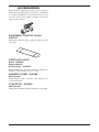
1
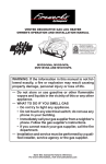
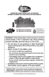
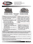
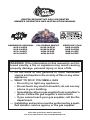
VENTED DECORATIVE GAS LOG HEATER
OWNER’S OPERATION AND INSTALLATION MANUAL
HARDWOOD ORIGINAL
HCA-18-RFN
HCA-24-RFN
HCA-18-RFP
HCA-24-RFP
CALIFORNIA MAPLE
HCM-18-RFN
HCM-24-RFN
HCM-18-RFP
HCM-24-RFP
KENTUCKY ELM
HKE-18-RFN
HKE-24-RFN
HKE-18-RFP
HKE-24-RFP
WARNING: If the information in this manual is not followed exactly, a fire or explosion may result causing
property damage, personal injury or loss of life.
— Do not store or use gasoline or other flammable
vapors and liquids in the vicinity of this or any other
appliance.
— WHAT TO DO IF YOU SMELL GAS
• Do not try to light any appliance.
• Do not touch any electrical switch; do not use any
phone in your building.
• Immediately call your gas supplier from a neighbor’s
phone. Follow the gas supplier’s instructions.
• If you cannot reach your gas supplier, call the fire
department.
— Installation and service must be performed by a qualified installer, service agency or the gas supplier.
Save this manual for future reference.
For more information, visit www.desatech.com
WARNING: Improper installation, adjustment, alteration, service or maintenance can cause injury or property damage. Refer to this manual for correct installation
and operational procedures. For assistance or additional information consult a qualified installer, service
agency or the gas supplier.
WARNING: This appliance is for installation only in
a solid-fuel burning masonry or UL127 factory-built
fireplace, constructed of noncombstible material and
connected to a working flue. (See page 6 for minimum
flue opening.
WARNING: This is a gas-fired heater. It uses air (oxygen) from the room in which it is installed. Provisions
for adequate combustion and ventilation air must be
provided. Refer to the National Fuel Gas Codes, ANSI
Z233.1/NFPA 54, Section 5.3, Air for Combustion and
Ventilation.
This appliance may be installed in an aftermarket,* permanently located, manufactured (mobile) home, where
not prohibited by local codes.
This appliance is only for use with the type of gas indicated on the rating plate. This appliance is not convertible for use with other gases.
* Aftermarket: Completion of sale, not for purpose of resale, from the manufacturer
State of Massachusetts: The installation must be made
by a licensed plumber or gas fitter in the Commonwealth
of Massachusetts.
TABLE OF CONTENTS
Safety Information ............................................... 3
Product Identification ........................................... 4
Local Codes ........................................................ 4
Unpacking ........................................................... 5
General Information ............................................. 5
Installation ........................................................... 5
Operating Appliance ............................................ 9
Inspecting Burners .............................................11
Cleaning and Maintenance ................................ 12
2
Technical Service .............................................. 12
Replacement Parts ............................................ 12
Troubleshooting ................................................. 13
Specifications .................................................... 15
Wiring Diagram .................................................. 15
Illustrated Parts Breakdown and Parts List ....... 16
Accessories ....................................................... 18
Warranty Information .............................Back Page
www.desatech.com
115481-01A
SAFETY INFORMATION
WARNING: This product contains and/or generates chemicals
known to the State of California
to cause cancer or birth defects
or other reproductive harm.
WARNING: Keep flue open
when operating unit.
IMPORTANT: Read this owner’s
manual carefully and completely
before trying to assemble, operate
or service this log set. Improper use
of this log set can cause serious
injury or death from burns, fire,
explosion, electrical shock and
carbon monoxide poisoning.
DANGER: Carbon monoxide
poisoning may lead to death!
Carbon Monoxide Poisoning: Early signs of carbon
monoxide poisoning resemble the flu, with headaches, dizziness or nausea. If you have these signs,
the log set may not be working properly. Get fresh
air at once! Have log set serviced. Some people
are more affected by carbon monoxide than others.
These include pregnant women, people with heart
or lung disease or anemia, those under the influence
of alcohol and those at high altitudes.
Natural & LP Gas: Natural & LP gas are odorless.
An odor-making agent is added to the gas. The
odor helps you detect a gas leak. However, the
odor added to the gas can fade. Gas may be present
even though no odor exists.
Make certain you read and understand all warnings.
Keep this manual for reference. It is your guide to
safe and proper operation of this log set.
WARNING: This appliance
is equipped for (natural or propane/LP) gas. Field conversion
is not permitted.
WARNING: Do not allow fans
to blow directly into the fireplace.
Avoid any drafts that alter burner
flame patterns.
WARNING: Installed decorative glass door enclosures must
be fully opened when operating
this gas appliance.
Due to high temperatures, the
appliance should be located out
of traffic and away from furniture
and draperies.
Do not place clothing or other
flammable material on or near
the appliance. Never place any
objects on the heater.
Heater assembly becomes very
hot when running heater. Keep
children and adults away from hot
surface to avoid burns or clothing
ignition. Heater will remain hot
for a time after shutdown. Allow
surface to cool before touching.
Carefully supervise young children when they are in the room
with appliance.
WARNING: Any change to
this log set or its controls can
be dangerous.
You must operate this heater
with a fireplace screen in place.
Make sure fireplace screen is
closed before running heater.
WARNING: Do not use a blower insert, heat exchanger insert or
other accessory not approved for
use with this appliance.
Keep the appliance area clear
and free from combustible materials, gasoline and other flammable vapors and liquids.
115481-01A
www.desatech.com
3
SAFETY INFORMATION
Continued
Children and adults should be
alerted to the hazard of high temperature and should stay away to
avoid burns or clothing ignition.
1. This appliance, as supplied, is only for use
with the type of gas indicated on the rating
plate. This appliance is not convertible for
use with other gases.
2. Do not place propane/LP supply tank(s) inside the structure. Locate propane/LP supply
tank(s) outdoors (propane/LP units only).
3. If you smell gas
• shut off gas supply
• do not try to light any appliance
• do not touch any electrical switch; do not use
any phone in your building
• immediately call your gas supplier from a
neighborʼs phone. Follow the gas supplierʼs
instructions
• if you cannot reach your gas supplier, call
the fire department
4. Never install the log set
• in a recreational vehicle
• where curtains, furniture, clothing or other
flammable objects are less than 42 inches
from the front, top or sides of the log set.
• in high traffic areas
• in windy or drafty areas
5. Before installing in a solid fuel burning fireplace,
the chimney flue and firebox must be cleaned of
soot, creosote, ashes and loose paint by a qualified
chimney cleaner. Creosote will ignite if highly
heated. Inspect chimney flue for damage. If damaged, repair flue before operating appliance.
6. If fireplace has glass doors, never operate with
glass doors closed, If you operate heater with
doors closed, heat buildup inside fireplace will
cause glass to burst. Also if fireplace opening
has vents at the bottom, you must open the
vents before operating heater.
7. To reduce the creation of soot, follow the instructions in Cleaning and Maintenance, page 12.
8. Do not run heater
• where flammable liquids or vapors are used
or stored
• under dusty conditions
9. Do not burn solid fuel in the fireplace after
installing the log set. Do not use this log set
to cook food or burn paper or other objects.
4
10. Log set becomes very hot when in use. Keep
children and adults away from hot surface to
avoid burns or clothing ignition. Log set will
remain hot for a time after shutdown. Allow
surface to cool before touching.
11. Carefully supervise young children when they
are in the room with the log set.
12. Do not use heater if any part has been exposed
to or under water. Immediately call a qualified
service technician to inspect the room heater
and to replace any part of the control system and
any gas control which has been under water.
13. Turn log set off and let cool before servicing,
installing or repairing. Only a qualified service
person should install, service or repair log set.
14. Provide adequate clearances around air
openings.
LOCAL CODES
Install and use log set with care. Follow all local
codes. In the absence of local codes, use the latest edition of the National Fuel Gas Code ANSI
Z223.1/NFPA 54*
*Available from:
American National Standards Institute, Inc.
1430 Broadway
New York, NY 10018
National Fire Protection Association, Inc.
Battery march park
Quincy, MA 02269
Hardwood Series gas log sets are certified by Omni
Test Laboratories to Z21.60A-2000/CGA 2.26A2000 as a vented decorative gas log set.
PRODUCT
IDENTIFICATION
Log Set
Assembly
Floor
Media Kit
Figure 1 - Product Identification
www.desatech.com
115481-01A
UNPACKING
CAUTION: Do not remove the
data plates from the grate assembly. The data plates contain
important warranty and safety
information.
1. Remove log set assembly from carton.
2. Remove all protective packaging applied to log
set for shipment.
3. Check all items for any shipping damage. If
damaged, promptly inform dealer where you
bought appliance.
GENERAL INFORMATION
These vented decorative gas log sets incorporate
uni-body constructed ceramic fiber logs and ember
bed burner which glow realistically when the appliance is in operation.
These units are remote controlled-decorative rated
and are equipped with millivolt gas valves. The
remote control allows for flame height adjustment,
timer and on/off control.
A spark ignition system (piezo) allows the gas
pilot to be lit without the use of matches or batteries and permits operation of the heater during
a power outage.
These log sets come with a Floor Media Kit included. This kit is used to blend the floor and the
log set together for a more natural look.
INSTALLATION
WARNING: A qualified service person must install heater.
Follow all local codes.
CAUTION: This heater creates
warm air currents. These currents
move heat to wall surfaces next
to heater. Installing heater next
to vinyl or cloth wall coverings or
operating heater where impurities
(such as, but not limited to, tobacco smoke, aromatic candles,
cleaning fluids, oil or kerosene
lamps, etc.) in the air exist, may
discolor walls or cause odors.
WARNING: Special care is
required if you are installing the
unit into a sunken fireplace. You
must raise the fireplace floor to
allow access to gas log controls.
This will insure adequate air
flow and guard against sooting.
Raise the fireplace floor using
noncombustible material.
CHECK GAS TYPE
Use the correct gas type (natural or propane/LP) for
your unit. If your gas supply is not correct, do not
instal in fireplace. Call dealer where you bought
the appliance for proper type of appliance.
WARNING: This appliance
is equipped for (natural or propane/LP) gas. Field conversion
is not permitted.
FLUE OPENING SPECIFICATIONS
WARNING: Before installing
in a solid fuel burning fireplace,
the chimney flue and firebox
must be cleaned of soot, creosote, ashes and loose paint by a
qualified chimney cleaner. Creosote will ignite if highly heated. A
dirty chimney flue may create and
distribute soot within the house.
Inspect chimney flue for damage.
If damaged, repair flue damper
before operating appliance.
115481-01A
Note: This vented appliance must be installed only
in a solid-fuel burning fireplace with a working
flue and constructed of noncombustible material.
The fireplace chimney must have a permanent vent
opening to outside of not less than 29 square inches
or as determined from manufacturer's installation
instructions.
LOG SIZING REQUIREMENTS
MINIMUM FIREBOX SIZE
LOG
FRONT REAR
SIZE HEIGHT DEPTH WIDTH WIDTH
18"
24"
www.desatech.com
14"
18"
16"
18"
30"
34"
20"
24"
5
INSTALLATION
PLACEMENT OF APPLIANCE
Continued
VENTING SPECIFICATIONS FOR
INSTALLATION
The fireplace chimney flue and vent must be drafting properly. To check the vent for proper drafting:
Light a tightly rolled newspaper on one end and
place it at the inside front edge of the fireplace.
Observe the smoke and be sure the vent is properly
drawing it up the chimney. If the smoke spills out
into the room, extinguish the flame and remove any
obstruction until proper venting is achieved.
The chimney flue damper must be fixed open to
provide a minimum of 29 square inch flue opeining at all times during operation of the log set. A
damper clamp can be used to secure the damper
(see Accessories, page 18). See the National Fuel
Gas Code ANSI Z223.1/NFPA 54, Section 6.6 for
details about minimum flue size.
INSTALLING DAMPER CLAMP
Secure the damper stop clam to the edge of the
damper as shown in Figure 2. If for any reason this
clamp doesn't work on your fireplace, another suitable clamp or permanent stop must be iinstalled, or
the damper blade must be cut or removed.
Damper
Clamp
Damper
Damper
Clamp
Damper
Masonry
Fireplace
Damper
Manufactured
Fireplace
Center the appliance in the fireplace. Make certain
the grate front feet sit inside the front edge of
the fireplace and that there is adequate clearance
around the appliance for access and operation.
CONNECTING TO GAS SUPPLY
WARNING: A qualified service
person must connect heater to gas
supply. Follow all local codes.
Installation Items Needed
Before installing heater, make sure you have the
items listed below.
• external regulator (propane/LP models only)
• piping (check local codes)
• sealant (resistant to propane/LP gas)
• equipment shutoff valve
• test gauge connection
• sediment trap
• tee joint
• pipe wrench
For propane/LP units, the installer must supply
an external regulator. The external regulator will
reduce incoming gas pressure. You must reduce
incoming gas pressure to between 11 and 14 inches
of water. If you do not reduce incoming gas pressure, heater regulator damage could occur. Install
external regulator with the vent pointing down as
shown in Figure 3. Pointing the vent down protects
it from freezing rain or sleet.
WARNING: Connecting
directly to an unregulated propane/LP tank may cause an
explosion.
Propane/LP
Supply Tank
External
Regulator
Figure 2 - Attaching Damper Clamp
Vent
Pointing
Down
Figure 3 - External Regulator with Vent
Pointing Down
6
www.desatech.com
115481-01A
INSTALLATION
Continued
The appliance gas inlet connection is 3/8" NPT at
the regulator, located at the rear of the appliance.
IMPORTANT: Hold appliance regulator with a
wrench to prevent movement when connecting
to inlet piping.
CAUTION: Use only new,
black iron or steel pipe. Internally-tinned copper tubing may
be used in certain areas. Check
your local codes. Use pipe of
1/2" diameter or greater to allow
proper gas volume to heater. If
pipe is too small, undue loss of
volume will occur.
Installation must include an equipment shutoff
valve, union and plugged 1/8" NPT tap. Locate NPT
tap within reach for test gauge hook up. NPT tap
must be upstream from log set (see Figure 4).
IMPORTANT: Install equipment shutoff valve in an
accessible location. The equipment shutoff valve is for
turning on or shutting off the gas to the appliance.
Apply pipe joint sealant lightly to male NPT
threads. This will prevent excess sealant from
going into pipe. Excess sealant in pipe could result
in clogged heater valves.
WARNING: Use pipe joint
sealant that is resistant to liquid
petroleum (LP) gas.
Install a sediment trap where it is within reach for
cleaning. Install in piping system between fuel
supply and heater. Locate sediment trap where
trapped matter is not likely to freeze. A sediment
trap traps moisture and contaminants. This keeps
them from going into heater controls. If sediment
trap is not installed or is installed wrong, heater
may not run properly.
115481-01A
Approved Flexible
CSA Design-Certified
Gas Hose (If
allowed by local Equipment Shutoff Valve
with 1/8" NPT Tap*
codes)
Natural
From Gas
Meter (5" W.C.**
to 10.5" W.C.
Pressure)
3" Minimum
Propane/LP
Pipe Cap Tee From External
Nipple
Joint Regulator (11"
W.C.** to 14"
W.C. Pressure)
Figure 4 - Gas Connection
* Purchase the optional CSA design-certified shutoff
valve from your dealer. See Accessories, page 18.
** Minimum inlet pressure for purpose of input
adjustment.
CHECKING GAS CONNECTIONS
WARNING: Test all gas piping
and connections for leaks after
installing or servicing. Correct
all leaks at once.
WARNING: Never use an
open flame to check for a leak.
Apply a noncorrosive leak detection fluid to all joints. Bubbles
forming show a leak. Correct all
leaks at once.
PRESSURE TESTING GAS SUPPLY
PIPING SYSTEM
Test Pressures In Excess Of 1/2 PSIG
(3.5 kPa)
1. Disconnect appliance with its appliance main
gas valve (control valve) and equipment
shutoff valve from gas supply piping system.
Pressures in excess of 1/2 psig will damage
heater regulator.
2. Cap off open end of gas pipe where equipment
shutoff valve was connected.
3. Pressurize supply piping system by either
opening propane/LP supply tank valve for
propane/LP gas or opening main gas valve
located on or near gas meter for natural gas
or using compressed air.
www.desatech.com
7
INSTALLATION
Equipment
Shutoff Valve
Continued
4. Check all joints of gas supply piping system.
Apply noncorrosive leak detection fluid to all
joints. Bubbles forming show a leak.
5. Correct all leaks at once.
6. Reconnect heater and equipment shutoff
valve to gas supply. Check reconnected fittings for leaks.
Test Pressures Equal To or Less Than
1/2 PSIG (3.5 kPa)
1. Close equipment shutoff valve (see Figure 5).
2. Pressurize supply piping system by either
opening propane/LP supply tank valve for
propane/LP gas or opening main gas valve
located on or near gas meter for natural gas
or using compressed air.
3. Check all joints from gas meter to equipment
shutoff valve for natural gas or propane/LP
supply to equipment shutoff valve for propane/
LP (see Figure 6 or 7). Apply noncorrosive
leak detection fluid to all joints. Bubbles
forming show a leak.
4. Correct all leaks at once.
Equipment
Shutoff
Valve
Open
Control Valve
Location
Figure 7 - Checking Gas Joints
(Natural Gas Only)
Gas Pressure Check
The appliance regulator controls the burner pressure which should be checked at the pressure test
point (1/8" NPT plugged tap) located near the on
the control valve identified OUT for the manifold
side and IN for inlet pressure. Make sure operating
pressures are within the limits shown in Specifications, page 15.
The pressure should be checked with the unit
burning and set to High. Replace test point plug
or tighten test screw after pressure measurement
ensuring no gas leaks.
PLACEMENT OF FLOOR MEDIA
Closed
Figure 5 - Equipment Shutoff Valve
Propane/LP
Supply Tank
Gas Meter
Equipment
Shutoff Valve
WARNING: Do not add extra logs or ornaments such as
pine cones, vermiculite or rock
wool. Using these added items
can cause sooting. Use only the
material included in the kits.
WARNING: Do not place lava
rock, embers or fiber log pieces on
logs or burners. This may cause
sooting. Place floor media material
only on the fireplace floor.
Control Valve
Location
Figure 6 - Checking Gas Joints
(Propane/LP Gas Only)
8
1. Place lava rock around base of unit making sure
the burner ports and valve access are not blocked
(see Figure 8, page 9). Retain a small amount of
lava rock to be used in step 4, page 9.
2. Place ember material around front and sides
of unit close to (but NOT on) the burner (see
Figure 9, page 9). Embers will "glow" when
heated to enhance the realistic look of your
log set.
www.desatech.com
115481-01A
INSTALLATION
Continued
3. Place fiber log pieces randomly on lava rock and
ember material around unit (see Figure 10).
4. Use remaining lava rock to blend the floor
media together. Your finished effect should
resemble Figure 11.
WARNING: Failure to position the floor media as shown in
Figures 8 through 11 or failure
to use only parts specifically
approved with this appliance
may result in property damage
or personal injury.
Figure 11 - Floor Media Kits Installed
OPERATING APPLIANCE
The RF Millivolt valve control used on these appliances allows you to turn the gas log set on or off; use
a timer to automatically operate the log set; increase
or decrease flame height, fan speed or timing. An
easy-to-read display gives you information about
room temperature, set temperature, flame height
level, fan speed level and a countdown timer, as
well as a low battery indication. Figure 12 shows
the location of the controls and indicators for the
transmitter (remote) and the receiver (valve).
Note: Fan operations are not applicable to these
Hardwood Series.
TRANSMITTER/REMOTE
Figure 8 - Placing Lava Rock
Display
Mode
Button
Timer
Button
Up Arrow
Down Arrow
RECEIVER/VALVE
Piezo
Figure 9 - Placing Ember Material
Manual
Switch
PilotStat
Knob
LED
Figure 12 - RF Millivolt Valve Controls
with Transmitter/Remote
Figure 10 - Placing Fiber Log Pieces
115481-01A
www.desatech.com
9
OPERATING HEATER
LIGHTING
INSTRUCTIONS
Continued
FOR YOUR SAFETY
READ BEFORE LIGHTING
WARNING: Keep flue open
when operating unit.
WARNING: If you do not follow these instructions exactly,
a fire or explosion may result
causing property damage, personal injury or loss of life.
A. This appliance has a pilot which must be
lighted with a piezo ignitor. When lightning
the pilot, follow these instructions exactly.
B. BEFORE LIGHTING smell all around the
appliance area for gas. Be sure to smell next
to the floor because some gas is heavier than
air and will settle on the floor.
WHAT TO DO IF YOU SMELL GAS
• Do not try to light any appliance.
• Do not touch any electric switch; do not
use any phone in your building.
• Immediately call your gas supplier from
a neighborʼs phone. Follow the gas
supplierʼs instructions.
• If you cannot reach your gas supplier, call
the fire department.
C. Use only your hand to push in or turn gas
control knob. Never use tools. If the knob
will not push in or turn by hand, do not try
to repair it, call a qualified technician. Force
or attempted repair may result in a fire.
D. Do not use this appliance if any part has
been under water. Immediately call a
qualified service technician to inspect the
appliance and to replace any part of the
control system and any gas control which
has been under water.
NOTICE: During initial operation
the appliance will emit a slight
odor for an hour or two. This is
due to the "burn-in" of the internal paints and lubricants used
in manufacturing. For the first
few hours, operate the appliance
with doors and windows open to
encourage dissipation of odor.
1. STOP! Read the safety information, column 1.
2. Make sure equipment shutoff valve is fully
open.
3. Set switch in the Local position.
4. Wait five (5) minutes to clear out any gas. If
you then smell gas STOP! Follow the safety
information above. If you don't smell gas,
go on to the next step.
5. Turn PilotStat knob to PILOT. Push in on
PilotStat knob and press Piezo button
until the pilot is lit.
6. Continue to hold PilotStat knob in until
LED blinks (one brief blink every two
seconds) then release knob. Note: You
will need to hold the knob in for about one
minute.
7. Turn PilotStat knob to ON See Figure 12,
page 9.
WARNING: Moving the Local/Remote switch can cause
the main burner to come on
immediately. Stand away from
the main burner when moving
the local/remote switch to avoid
possible injury.
USING TRANSMITTER/
REMOTE
1. Move switch to REMOTE position (see
Figure 12, page 9).
2. Press FAN
or FLAME
key within
30 seconds.
3. Make sure LED turns on for one second.
10
www.desatech.com
115481-01A
OPERATING HEATER
Continued
4. Press MODE
button until mode
shows in display window of transmitter/
remote. Press up or down key to change
set temperature.
5. To set delay timer, press TIMER
button
followed by either the up or down key.
6. To change the flame height, press the
button until mode is ON. Press
MODE
the FLAME
button and press the up or
down arrow key.
7. To change between Fahrenheit and Celsius,
press the up and down arrow keys at the same
time and hold for at least three seconds.
Figure 13 - Correct Pilot Flame Pattern
TO TURN OFF GAS
TO APPLIANCE
Shut Off Main Burner Using Remote
Press MODE
button until mode is OFF.
Pilot stays lit.
Shut Off Main Burner Without Remote
Turn PilotStat knob to PILOT. Pilot stays lit.
Hardwood Original Log Set
Shut Off Main Burner and Pilot
Turn PilotStat knob to OFF.
CAUTION: During normal
shutdown of this unit, a flash
may be observed due to the nature of the burner components.
Remain clear of the unit during
the shutdown process.
California Maple Log Set
INSPECTING BURNERS
Check pilot flame pattern and burner flame patterns often.
Flames from the pilot should always be present when
the appliance is in operation (see Figure 13).
The flame should look similar to those in Figure 14.
The flames should look random in appearance with
the ember bed glowing red-orange in color.
Kentucky Elm Log Set
Figure 14 - Log Sets with Flame Patterns
115481-01A
www.desatech.com
11
CLEANING AND
MAINTENANCE
WARNING: Turn off the appliance and allow to cool before
cleaning.
CAUTION: You must keep
control areas, burners and
circulating air passageways of
fireplace clean. Inspect these
areas of fireplace before each
use. Have fireplace and chimney
(if applicable) inspected yearly
by a qualified service person.
Fireplace may need more frequent cleaning due to excessive
lint from carpeting, bedding
material, etc.
Only limited cleaning will be required under normal use of this appliance. Dust the front grate and
top of receiver/valve. Do not use cleaning fluids to
clean logs or any other part of the appliance.
If, after a period of use, the flames start to exhibit
unusual shapes and behavior or the burner fails to
ignite smoothly, then the burner holes may require
some cleaning. If this happens, we recommend
that you contact your nearest authorized service
technician to get the appliance serviced.
TRANSMITTER
TECHNICAL SERVICE
You may have further questions about installation,
operation or troubleshooting. If so, contact DESAʼs
Technical Service Department at 1-866-672-6040.
When calling please have your model and serial
numbers of your heater ready.
You can also visit DESAʼs technical services web
site at www.desatech.com.
REPLACEMENT PARTS
Note: Use only original replacement parts. This
will protect your warranty coverage for parts
replaced under warranty.
PARTS UNDER WARRANTY
Contact authorized dealers of this product. If they
canʼt supply original replacement part(s), call DESAʼs
Technical Service Department at 1-866-672-6040.
When calling DESA, have ready
• your name and address
• model and serial numbers of your log set
• how log set was malfunctioning
• type of gas used (propane/LP or natural gas)
• purchase date
Usually, we will ask you to return the part to the
factory.
PARTS NOT UNDER WARRANTY
Contact authorized dealers of this product. If they
canʼt supply original replacement part(s), call
DESA at 1-866-672-6040 for referral information.
When calling DESA, have ready
• model number of your log set
• the replacement part number
If the battery light is on or the display is blank,
you will need to replace the three AAA batteries
in transmitter/remoter. To change batteries in the
transmitter/remote, slide the battery compartment
door off to expose old batteries. Place new batteries
into housing and reattach door. See Figure 15.
Figure 15 - Bottom of Transmitter,
Showing Battery Compartment and Door
12
www.desatech.com
115481-01A
TROUBLESHOOTING
Note: In normal operation, LED blinks once
every two seconds; also, LED will be on for one
second after every valid command received by the
receiver/valve' these are not error codes.
Failure codes can occur anytime after the pilot
burner is lit. Failure code timing is 1/4 second
on, 1/2 second off.
Sequence is failure code followed by LED not
blinking for four seconds.
In the event of multiple failure codes, the next
failure code follows the previous failure code by
approximately 3 seconds.
LED Failure Code
(No. of Blinks)
Service Action
8
Replace valve.
7
Confirm stepper motor
connection exists.
5
Confirm fan connection
exists and works.
3
Replace thermopiles.
2
Device too hot. Turn on fan
or if applicable, open glass
doors.
1 short blink
Normal operation
LED Failure Codes and Service Action
WARNING: Turn off and unplug heater and let cool before servicing.
Only a qualified service person should service and repair heater.
IMPORTANT: Valve system troubleshooting should only be accomplished by a qualified service technician.
Note: Before troubleshooting the gas control system, be sure external gas shut off valve (located at gas
supply inlet) is in the "ON" position.
OBSERVED PROBLEM
POSSIBLE CAUSE
REMEDY
Spark ignitor will not light pilot
after repeated triggering of ignitor button
1. Defective ignitor (no spark
at electrode)
1. Check for spark at electrode
and pilot; if no spark and
electrode wire is properly
connected, replace ignitor
2. Using a match, light pilot. If
pilot lights, turn off pilot and
trigger the ignitor button again.
If pilot lights, an improper gas
mixture caused the bad lighting
and a longer purge period is
recommended. If pilot will not
light, check gap at electrode
and pilot - gap should be 1/8"
to have a strong spark. If gap
measures 1/8", replace pilot
3. Check inlet gas pressure. It
should be within the limits as
marked on the rating plate
4. Clean or replace pilot orifice
2. Defective or misaligned
electrode at pilot (spark at
electrode)
3. Gas supply pressure errant
4. Pilot orifice plugged
Pilot will not stay lit after carefully following the lighting
instructions
115481-01A
1. Defective pilot generator
(thermocouple)
www.desatech.com
1. Check pilot flame, it must
impinge on thermocouple
(see Figure 13, page 11).
Clean and/or adjust pilot for
maximum flame impingement
on thermocouple. Ensure that
the connection between the
valve and thermocouple are
tight and secure.
13
TROUBLESHOOTING
Continued
OBSERVED PROBLEM
POSSIBLE CAUSE
REMEDY
Pilot burning, no gas to burner,
valve knob "ON", wall switch
"ON"
1. Wa l l s w i t c h o r w i r e s
defective
1. Check wall switch and wires
for proper connections. Jumper wire across terminals at wall
switch. If burner comes on,
replace defective wall switch.
If okay, jumper wires across
wall switch wires at valve. If
burner comes on, wires are
faulty or connections are bad
2. Check thermopile with millivolt meter. Take reading at
thermopile terminals of gas
valve. It should read 325 millivolts minimum with optional
wall switch "OFF". Replace
faulty thermopile if reading is
below specified minimum.
3. Check burner orifice for stoppage and remove
2. Thermopile may not be
generating sufficient millivoltage.
3. Plugged burner orifice
Frequent pilot/burner outage
problem
14
1. Pilot flame may be too low
or blowing (high) causing
the pilot/valve safety to drop
out
www.desatech.com
1. Clean and/or adjust pilot flame
for maximum flame impingement on thermocouple (see
Figure 13, page 11)
115481-01A
SPECIFICATIONS
HCA-24-RFN
HCM-24-RFN
HKE-24-RFN
Btu (Variable)
45,000/67,000
Type Gas
Natural Gas Only
Ignition
Piezo
Manifold Pressure 3.5" - 1.6"W.C.
Inlet Gas Pressure (in. of water)
Maximum
10.5" W.C.
Minimum*
5.0" W.C.
Valve Operation
RF Millivolt
Orifice Size
#21
HCA-24-RFP
HCM-24-RFP
HKE-24-RFP
43,000/65,000
Propane/LP Only
Piezo
10" - 6.3"W.C.
HCA-18-RFN
HCM-18-RFN
HKE-18-RFN
41,000/56,000
Natural Gas Only
Piezo
3.5" - 1.6"W.C.
HCA-18-RFP
HCM-18-RFP
HKE-18-RFP
42,000/51,000
Propane/LP Only
Piezo
10" - 6.3"W.C.
13" W.C.
11" W.C.
RF Millivolt
#42
10.5" W.C.
5.0" W.C.
RF Millivolt
#28
13" W.C.
11" W.C.
RF Millivolt
#45
* For purpose of input adjustment
WIRING DIAGRAM
REMOTE CONTROL
(MILLIVOLT)
Outlet
Pressure
Tap
Inlet
Pressure
Tap
Pilot
Burner
Assembly
Piezo
Pilot Tube
Gas Control
Local and
Remote Switch Knob
POWER SUPPLY. PROVIDE
DISCONNECT MEANS AND
OVERLOAD PROTECTION AS
REQUIRED.
Pilot
Adjustment
Screw
Thermopile
Leadwires
Figure 16 - Millivolt System Wiring Diagram
115481-01A
www.desatech.com
15
ILLUSTRATED PARTS BREAKDOWN
HCA-24-RFN, HCA-24-RFP, HCA-18-RFN, HCA-18-RFP, HCM-24-RFN,
HCM-24-RFP, HCM-18-RFN, HCM-18-RFP, HKE-24-RFN, HKE-24-RFP,
HKE-18-RFN, HKE-18-RFP
8
6
10
7
9
12
13
16
17
5
3
15
1
11
2
16
www.desatech.com
4
115481-01A
PARTS LIST
This list contains replaceable parts used in your heater. When ordering parts, follow the instructions
listed under Replacement Parts on page 12 of this manual.
PART NUMBER
HCA-24-RFN HCA-24-RFP HCA-18-RFN HCA-18-RFP
KEY HCM-24-RFN HCM-24-RFP HCM-18-RFN HCM-18-RFP
NO. HKE-24-RFN HKE-24-RFP HKE-18-RFN HKE-18-RFP DESCRIPTION
1
2
3
4
5
6
7
8
9
10
11
12
13
14
15
16
17
111814-01
115453-01
115457-01
111815-01
111809-01
115490-01
115449-01
104489-01
115491-01
115454-01
115452-01
115488-01
14396
115489-01
115450-01
115456-01
114394-01
111814-02
115453-01
115457-01
111815-01
111809-02
115490-02
115449-01
104489-01
115492-01
115454-01
115452-01
115488-01
14396
115489-01
115450-01
115456-01
114394-01
111814-01
115453-01
115458-01
111815-01
111809-01
115490-03
115448-01
104489-01
115492-01
115454-01
115452-01
115488-01
14396
115489-01
115451-01
115456-01
114394-01
111814-02
115453-01
115458-01
111815-01
111809-02
115490-04
115448-01
104489-01
115493-01
115454-02
115452-01
115488-01
14396
115489-01
115451-01
115456-01
114394-01
111288-02
112363-01
111288-02
112363-01
111288-02
112363-01
111288-02
112363-01
112364-01
112364-01
112364-01
112364-01
112799-01
GA6060
112799-01
GA6060
112799-01
GA6060
112799-01
GA6060
Gas Valve
Valve/Pilot Bracket
Log Burner
Transmitter/Remote
Pilot
Orifice
Grate
Gasket
Air Shutter
Venturi
Valve Bracket
Tube
Adapter Valve
Adapter Orifice
Burner Plate
Log Support Plate
Pilot Shield
QTY.
1
1
1
1
1
1
1
1
1
1
1
1
1
1
1
1
1
PARTS AVAILABLE NOT SHOWN
Flex Gas Line
Ember Chunk Kit #1
(3 Pieces)
Ember Chunk Kit #2
(2 Pieces)
Ember Flakes Kit
Lava Rock
1
1
1
1
1
1
LOG SET ASSEMBLIES
MODELS
115481-01A
PART NO.
HCA-24-RFN/P
115474-01
HCM-24-RFN/P
115471-01
HKE-24-RFN/P
115473-01
HCA-18-RFN/P
115469-01
HCM-18-RFN/P
115470-01
HKE-18-RFN/P
115472-01
www.desatech.com
17
ACCESSORIES
Purchase these appliances from your local dealer.
If they can not supply these accessories, call DESA
at 1-866-672-6040 for referral informatioin. You
can also write to the address listed on the back
page of this manual.
EQUIPMENT SHUTOFF VALVE
GA5010
Equipment shutoff valve with 1/8" NPT tap. Fits
1/2" pipe.
FIREPLACE HOOD
Black - GA6050
Brass-GA6052
Antique Brss - GA6053
Helps deflect heat away from mantel or wall ab ove
fireplace. Fits opening 28" to 4" wide.
DAMPER CLAMP - GA6080
(Not Shown)
Permanently opens chimney flue damper for
vented operation.
LAVA ROCK - GA6060
(Not Shown)
Order when additional rock is desired (1.8 lb. bag)
18
www.desatech.com
115481-01A
NOTES
_____________________________________________________
______________________________________________________
______________________________________________________
______________________________________________________
______________________________________________________
______________________________________________________
______________________________________________________
______________________________________________________
______________________________________________________
______________________________________________________
______________________________________________________
______________________________________________________
______________________________________________________
_____________________________________________________
______________________________________________________
______________________________________________________
______________________________________________________
______________________________________________________
______________________________________________________
______________________________________________________
______________________________________________________
______________________________________________________
115481-01A
www.desatech.com
19
WARRANTY INFORMATION
KEEP THIS WARRANTY
Model
Serial No.
Date Purchased
Always specify model and serial numbers when communicating with the factory.
We reserve the right to amend these specifications at any time without notice. The only warranty applicable is our
standard written warranty. We make no other warranty, expressed or implied.
LIMITED WARRANTY
VENT-FREE FIREBOX
DESA warrants this product to be free from defects in materials and components for four (4) years from the date
of first purchase, provided that the product has been properly installed, operated and maintained in accordance
with all applicable instructions. To make a claim under this warranty the Bill of Sale or cancelled check must
be presented.
This warranty is extended only to the original retail purchaser. This warranty covers the cost of part(s) required to
restore this heater to proper operating condition and an allowance for labor when provided by a DESA Authorized
Service Center. Warranty part(s) MUST be obtained through authorized dealers of this product and/or DESA who
will provide original factory replacement parts. Failure to use original factory replacement parts voids this warranty.
The heater MUST be installed by a qualified installer in accordance with all local codes and instructions furnished
with the unit.
This warranty does not apply to parts that are not in original condition because of normal wear and tear or parts
that fail or become damaged as a result of misuse, accidents, lack of proper maintenance or defects caused by
improper installation. As with all concrete liners, this liner may develop slight cracks when exposed to heat. This
cracking is considered normal. Travel, diagnostic cost, labor, transportation and any and all such other costs related
to repairing a defective heater will be the responsibility of the owner.
TO THE FULL EXTENT ALLOWED BY THE LAW OF THE JURISDICTION THAT GOVERNS THE SALE OF
THE PRODUCT; THIS EXPRESS WARRANTY EXCLUDES ANY AND ALL OTHER EXPRESSED WARRANTIES AND LIMITS THE DURATION OF ANY AND ALL IMPLIED WARRANTIES, INCLUDING WARRANTIES
OF MERCHANTABILITY AND FITNESS FOR A PARTICULAR PURPOSE TO FOUR (4) YEARS ON ALL
COMPONENTS FROM THE DATE OF FIRST PURCHASE; AND DESAʼS LIABILITY IS HEREBY LIMITED
TO THE PURCHASE PRICE OF THE PRODUCT AND DESA SHALL NOT BE LIABLE FOR ANY OTHER
DAMAGES WHATSOEVER INCLUDING INDIRECT, INCIDENTAL OR CONSEQUENTIAL DAMAGES.
Some states do not allow a limitation on how long an implied warranty lasts or an exclusion or limitation of
incidental or consequential damages, so the above limitation on implied warranties or exclusion or limitation on
damages may not apply to you.
This warranty gives you specific legal rights and you may also have other rights that vary from state to state.
For information about this warranty write:
2701 Industrial Drive
P.O. Box 90004
Bowling Green, KY 42102-9004
www.desatech.com
115481-01
NOT A UPC
115481-01
Rev. A
02/05