1
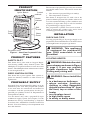
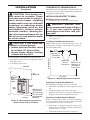
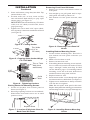
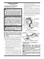
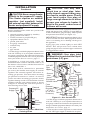
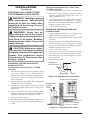
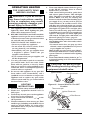
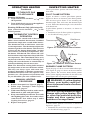
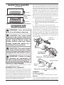
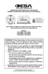
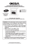
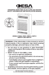
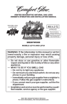
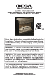
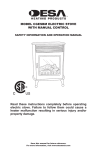
BLUE FLAME VENT-FREE PROPANE/LP GAS HEATER
OWNER’S OPERATION AND INSTALLATION MANUAL
MODELS REM10PT AND RH10PT
10,000 Btu/Hr Thermostatically-Controlled Heater
WARNING: If the information in this manual is not followed exactly, a fire or explosion may result causing
property damage, personal injury or loss of life.
— Do not store or use gasoline or other flammable
vapors and liquids in the vicinity of this or any other
appliance.
— WHAT TO DO IF YOU SMELL GAS
• Do not try to light any appliance.
• Do not touch any electrical switch; do not use any
phone in your building.
• Immediately call your gas supplier from a neighbor’s
phone. Follow the gas supplier’s instructions.
• If you cannot reach your gas supplier, call the fire
department.
— Installation and service must be performed by a qualified installer, service agency or the gas supplier.
Save this manual for future reference.
For more information, visit www.desatech.com
WARNING: Improper installation, adjustment, alteration, service or maintenance can cause injury or property damage. Refer to this manual for correct installation
and operational procedures. For assistance or additional information consult a qualified installer, service
agency or the gas supplier.
WARNING: This is an unvented gas-fired heater. It uses
air (oxygen) from the room in which it is installed. Provisions for adequate combustion and ventilation air must
be provided. Refer to Air for Combustion and Ventilation
section on page 5 of this manual.
This appliance is only for use with the type of gas indicated on the rating plate. This appliance is not convertible for use with other gases.
State of Massachusetts: The installation must be made by a licensed plumber or gas fitter in the
Commonwealth of Massachusetts.
Sellers of unvented propane or natural gas-fired supplemental room heaters shall provide to each
purchaser a copy of 527 CMR 30 upon sale of the unit.
Vent-free gas products are prohibited for bedroom and bathroom installation in the Commonwealth of Massachusetts.
TABLE OF CONTENTS
Safety Information ............................................... 3
Local Codes ........................................................ 4
Unpacking ........................................................... 4
Product Identification ........................................... 5
Product Features ................................................. 5
Propane/LP Supply.............................................. 5
Installation ........................................................... 5
Operating Heater ................................................11
Inspecting Heater .............................................. 12
Cleaning and Maintenance ................................ 13
2
Troubleshooting ................................................. 14
Storage .............................................................. 17
Specifications .................................................... 17
Service Hints ..................................................... 17
Technical Service .............................................. 17
Service Publications .......................................... 17
Accessories ....................................................... 17
Replacement Parts ............................................ 17
Illustrated Parts Breakdown and Parts List ....... 18
Warranty Information ...........................Back Cover
www.desatech.com
110373-01E
SAFETY INFORMATION
WARNING: This product contains and/or generates chemicals
known to the State of California
to cause cancer or birth defects
or other reproductive harm.
IMPORTANT: Read this owner’s
manual carefully and completely
before trying to assemble,
operate or service this heater.
Improper use of this heater can
cause serious injury or death
from burns, fire, explosion,
electrical shock and carbon
monoxide poisoning.
DANGER: Carbon monoxide
poisoning may lead to death!
Carbon Monoxide Poisoning: Early signs of carbon
monoxide poisoning resemble the flu, with headaches, dizziness or nausea. If you have these signs,
the heater may not be working properly. Get fresh
air at once! Have heater serviced. Some people
are more affected by carbon monoxide than others.
These include pregnant women, people with heart
or lung disease or anemia, those under the influence
of alcohol and those at high altitudes.
Propane/LP Gas: Propane/LP gas is a fuel gas.
Fuel gases are odorless. An odor-making agent
is added to fuel gases. The odor helps you detect
a fuel gas leak. However, the odor added to fuel
gas can fade. Fuel gas may be present even though
no odor exists.
Make certain you read and understand all warnings. Keep this manual for reference. It is your
guide to safe and proper operation of this heater.
WARNING: Any change to
this heater or its controls can
be dangerous.
WARNING: Do not use a
blower insert, heat exchanger
insert or other accessory not approved for use with this heater.
110373-01E
WARNING: If the recreational
or commercial enclosure does
not have a window or roof vent,
DO NOT USE THIS HEATER
inside.
This heater should be inspected
before each use. Frequent cleaning may be required. The control
compartments, burners and circulating air passageways of the
heater must be kept clean.
Due to high temperatures, the
appliance should be located out
of traffic and away from combustible materials.
Children and adults should be
alerted to the hazard of high
surface temperature and should
stay away to avoid burns or
clothing ignition.
Do not place clothing or other
flammable material on or near
the appliance. Never place any
objects on the heater.
Heater will remain hot for a time
after shutdown. Allow surface to
cool before touching.
Young children should be carefully supervised when they are
near the heater.
Any safety screen or guard
removed for servicing the appliance must be replaced prior
to operating the heater.
Keep the appliance area clear
and free from combustible materials, gasoline and other flammable vapors and liquids.
www.desatech.com
3
SAFETY INFORMATION
Continued
1. Install and use heater with care. Follow all
local ordinances and codes. In the absence
of local ordinances and codes, refer to the
Standard for Storage and Handling of Liquefied Petroleum Gas, ANSI/NFPA 58 and the
Natural Gas Installation Code, CAN/CGA
B149.2. This instructs on the safe storage and
handling of propane/LP gases.
2. This appliance is only for use with the type
of gas indicated on the rating plate. This appliance is not convertible for use with other
gases.
3. This heater may be used in a recreational
enclosure or temporary construction work
enclosure with a remote refillable propane/LP
cylinder ONLY when the cylinder is located
outdoors and the heater is used with the hose
kit #LPA3090 (included with this heater).
NEVER bring a refillable propane/LP cylinder
indoors. A fire or explosion can occur causing
property damage, serious injury or death.
4. Use only the hose and factory preset regulator
provided with the heater. Use only replacement
pressure regulators and hose assemblies specified in this manual. See Accessories, page 17.
5. Inspect the hose before each use of the heater.
If it is evident there is excessive abrasion or
wear or the hose is cut, it must be replaced
prior to the heater being put into operation.
Use replacement hose assembly kit #LPA3090
(see Accessories, page 17).
6. Use only propane gas set up for vapor withdrawal.
7. This heater shall not be installed in a bedroom
or bathroom.
8. This heater needs fresh, outside air ventilation
to run properly. This heater has an Oxygen
Depletion Sensing (ODS) safety shutoff system. The ODS shuts down the heater if not
enough fresh air is available. You must provide
a minimum 10 square inches of ventilation air
for adequate combustion.
9. If heater shuts off, do not relight until you
provide fresh, outside air. If heater keeps
shutting off, have it serviced.
10. Keep all air openings in front and bottom of
heater clear and free of debris. This will insure
enough air for proper combustion.
4
11. Do not use heater if any part has been under
water. Immediately call a qualified service
technician to inspect the room heater and to
replace any part of the control system and any
gas control which has been under water.
12. Turn off and let cool before servicing. Only
a qualified service person should service and
repair heater.
13. Operating heater above elevations of 4,500
feet could cause pilot outage.
14. Turn off propane/LP supply when not in use.
15. Check heater for damage before each use. Do
not use a damaged heater.
16. Do not alter heater. Keep heater in its original
state.
17. Do not use heater if altered.
18. This heater can only be used in a recreational
or commercial enclosure with a window or
roof vent. This heater is not for outdoor use.
19. Before using the heater provide adequate
ventilation. An area of 10 square inches of
opening of a window or roof vent is needed
for adequate combustion and ventilation air.
LOCAL CODES
Install and use heater with care. Follow all local codes. In the absence of local codes, use the
latest edition of National Fuel Gas Code, ANSI
Z223.1/NFPA 54*.
*Available from:
American National Standards Institute, Inc.
1430 Broadway
New York, NY 10018
National Fire Protection Association, Inc.
Batterymarch Park
Quincy, MA 02269
UNPACKING
1. Remove heater from carton.
2. Remove all protective packaging applied to
heater for shipment.
3. Check heater for any shipping damage. If
heater is damaged, promptly return to dealer
where you bought heater.
www.desatech.com
110373-01E
PRODUCT
IDENTIFICATION
Ignitor Button
Control
Knob
Heater
Cabinet
Grill
Guard
Front
Panel
The amount of propane/LP gas ready for use from
propane/LP tanks varies. Two factors decide this
amount:
1. The amount of propane/LP gas in tank(s)
2. The temperature of tank(s)
This heater is designed for use with a 20 or 40
pound refillable propane/LP cylinder when used
as a self contained heating system (with hose and
regulator). Larger tanks may be used if installed
in a permanent gas supply system.
The propane/LP cylinder used must include a
collar to protect the cylinder valve and a listed
overfilling prevention device (OPD).
Glass
Panel
INSTALLATION
CHECK GAS TYPE
Use only propane/LP gas. If your gas supply is not
propane/LP, do not install heater. Call dealer where
you bought heater for proper type heater.
Regulator Hose
Figure 1 - Vent-Free Propane/LP Gas
Heater
PRODUCT FEATURES
SAFETY PILOT
This heater has a pilot with an Oxygen Depletion Sensing (ODS) safety shutoff system. The
ODS/pilot is a required feature for vent-free room
heaters. The ODS/pilot shuts off the heater if there
is not enough fresh air.
PIEZO IGNITION SYSTEM
This heater has a piezo ignitor. This system requires no matches, batteries or other sources to
light heater.
PROPANE/LP SUPPLY
Propane/LP gas and propane/LP tank(s) are to be
furnished by the user. The propane/LP cylinder
to be used must be constructed and marked in
accordance with the specifications for the propane/LP gas cylinders of the U.S. Department of
Transportation (DOT).
Use this heater only with a propane/LP vapor
withdrawal supply system. See Chapter 5 of the
Standard for Storage and Handling of Liquefied
Petroleum Gas, ANSI/NFPA 58 and/or CAN/CGA
B149.2. Your local library or fire department will
have this booklet.
110373-01E
WARNING: This appliance
is equipped for propane/LP
gas. Field conversion is not
permitted.
LOCATING HEATER
WARNING: Maintain the minimum clearances shown in Figure
2, page 6. If you can, provide
greater clearances from floor,
ceiling and joining wall.
WARNING: Never install the
heater
• in a bedroom or bathroom
• where curtains, furniture,
clothing or other flammable
objects are less than 36" from
the front, top or sides of the
heater
• as a fireplace insert
• in high traffic areas
• in windy or drafty areas
www.desatech.com
5
INSTALLATION
THERMOSTAT SENSING BULB
CAUTION: This heater creates warm air currents. These
currents move heat to wall surfaces next to heater. Installing
heater next to vinyl or cloth wall
coverings or operating heater
where impurities (such as, but
not limited to, tobacco smoke,
aromatic candles, cleaning fluids, oil or kerosene lamps, etc.) in
the air exist, may discolor walls
or cause odors.
CAUTION: If you install the
heater in a home garage
• heater pilot and burner must
be at least 18" above floor.
• locate heater where moving
vehicle will not hit it.
For convenience and efficiency, install heater
• where there is easy access for operation, inspection and service
• in coldest part of room
CEILING
6"
Minimum
From
Sides Of
Heater
The thermostat sensing bulb is located inside the
heater. Do not move this bulb during installation
or operation of the heater.
INSTALLING HEATER TO WALL
Marking Screw Locations
1. Determine where you will locate heater.
WARNING: Maintain minimum clearances shown in Figure
3. If you can, provide greater
clearances from floor and joining wall.
2. Mark two mounting screw locations on wall
(see Figure 3).
Installing Two Mounting Screws
Note: Wall anchors and mounting screws are
in hardware package. The hardware package is
provided with heater.
8 7/8"
Minimum To
Maintain 6"
Clearance
From Wall
JOINING WALL
Continued
7 3/4"
Mounting
Screw
Locations
20 1/4"
Minimum To
Maintain 3"
Clearance
From Floor
36"
Minimum
FLOOR
Figure 3 - Mounting Screw Locations
Attaching To Wall Stud Method
For attaching mounting screw to wall stud
Right
1. Drill hole at marked location using 9/64" drill
Side
Left
Side
bit.
Minimum To
Top Surface
2. Insert mounting screw into wall stud.
Of Carpeting,
3. Tighten screw until 1/16" space (thickness of
3" Tile
Minimum
To Top Surface
Or Other
penny) is between screwhead and wall.
Of Carpeting, Tile Or Other
Combustible
Combustible Material
Attaching To Wall Anchor Method
FLOOR
Material
Follow instructions below to attach mounting
Figure 2 - Mounting Clearances As
screws to hollow walls (wall areas between studs)
Viewed From Front of Heater
or solid walls (concrete or masonry).
1. Drill holes at marked locations using 5/16"
drill bit. For solid walls (concrete or masonry),
drill at least 1 1/4" deep.
2. Fold wall anchor (see Figure 4, page 7).
6
www.desatech.com
110373-01E
INSTALLATION
Continued
3. Insert wall anchor (wings first) into hole. Tap
anchor flush to wall.
4. For thin walls (1/2" or less), insert red key
into wall anchor. Push red key to “pop” open
anchor wings (see Figure 5).
IMPORTANT: Do not hammer key! For thick
walls (over 1/2" thick) or solid walls, do not
pop open wings.
5. Tighten two screws until 1/16" space (thickness of penny) is between screwheads and wall
(see Figure 6).
Removing Front Panel Of Heater
1. Remove two screws near bottom corners of
front panel.
2. Lift straight up on grill guard until it stops.
Grill guard will slide up about 1/4".
3. Pull bottom of front panel forward, then
down.
Figure 4 - Folding Anchor
Thin Walls
(1/4" to
1/2" thick)
Figure 5 - Popping Open Anchor Wings
For Thin Walls
Thin or Thick
Wall (thick
wall shown)
1/16"
Space
Solid
Wall
Figure 6 - Tightening Anchors
Placing Heater On Mounting Screws
1. Locate two keyhole slots on back panel of
heater (see Figure 7).
2. Place large openings of slots over screwheads.
Slide heater down until screws are in small
portion of slots.
Figure 8 - Removing Front Panel Of
Heater
Installing Bottom Mounting Screw
1. Locate bottom mounting hole. This hole is
near bottom on back panel of heater (see
Figure 9).
2. Mark screw location on wall.
3. Remove heater from wall.
4. If installing bottom mounting screw into hollow or solid wall, install wall anchor. Follow
steps 1 through 5 under Attaching To Wall
Anchor Method, page 6. If installing bottom
mounting screw into wall stud, drill hole at
marked location using 9/64" drill bit.
5. Replace heater on wall.
6. Insert bottom anchor screw through back panel
into bottom anchor or drilled hole (see Figure 9).
7. Tighten screw until heater is firmly secured to
wall. Do not over tighten.
Note: Do not replace front panel at this time.
Replace front panel after making gas connections
and checking for leaks (see pages 8 through 10).
Keyhole Slots
Figure 7 - Location Of Keyhole Slots On
Back Panel Of Heater
110373-01E
Figure 9 - Installing Bottom Mounting
Screw
www.desatech.com
7
INSTALLATION
Continued
CONNECTING TO PORTABLE
CYLINDER GAS SUPPLY
WARNING: Review and understand the warnings in the
Safety Information section, page
3. They are needed to safely operate this heater. Follow all local
codes when using this heater.
6.
7.
8.
9.
places the regulator vent in the proper position
to protect it from the weather.
Connect hose to heater inlet. Tighten firmly
using a wrench. You must use the regulator
supplied with heater.
Open propane/LP supply valve on propane/LP
tank(s) slowly. Note: If not opened slowly,
excess-flow check valve on propane/LP tank
may stop gas flow. If this happens, close propane/LP supply valve and open again slowly.
Check all connections for leaks. Apply a noncorrosive leak detection fluid to gas joints. Bubbles
forming show a leak that must be corrected.
Close propane/LP supply valve.
WARNING: Test all gas piping
and connections for leaks after
installation or servicing. Never
use an open flame to check for
a leak. Apply a noncorrosive
leak detection fluid to all joints.
Bubbles forming show a leak.
Correct all leaks at once.
WARNING: Use pipe joint
sealant that is resistant to liquid
petroleum (LP) gas.
Never bring a refillable propane/LP cylinder indoors. A fire
or explosion can occur causing
property damage, serious injury
or death.
IMPORTANT: You must use a propane/LP gas
supply cylinder that is compatible with the connection device provided with the hose and regulator.
1. Remove 90° gas fitting from hardware bag.
2. Apply pipe joint sealant lightly to male NPT
threads (see Figure 10). This will prevent excess
sealant from going into pipe. Excess sealant in
pipe could result in clogged heater valves.
3. Hold gas pressure regulator with wrench when
connecting the 90° gas fitting. Do not over
tighten connection to regulator. The regulator
body could be damaged.
4. Provide propane/LP supply system (see Propane/LP Supply, page 5).
5. Connect fuel gas fitting on hose/regulator assembly to propane/LP tank(s). Turn fuel gas fitting
counterclockwise into threads on tank. Tighten
firmly using a wrench. IMPORTANT: Position
regulator so that hose leaving the regulator is
in a horizontal position (see Figure 11). This
8
Pressure
Regulator
Heater
Cabinet
Apply Sealant To
This End Only
Hose Fitting
Elbow
Hose To
Regulator
Figure 10 - Gas Connection
Propane/LP
Supply Valve
Propane/LP
Tank
Regulator
Hose To
Heater
Fuel Gas
Fitting
Figure 11 - Regulator Position
CONNECTING TO PERMANENT
GAS SUPPLY
WARNING: This appliance
requires a 3/8" NPT (National
Pipe Thread) inlet connection to
the pressure regulator.
WARNING: A qualified service person must connect heater
to gas supply. Follow all local
codes.
www.desatech.com
110373-01E
CAUTION: Never connect heater
directly to the propane/LP supply.
This heater requires an external
regulator (not supplied). Install
the external regulator between the
heater and propane/LP supply.
Installation Items
Before installing heater, make sure you have the
items listed below.
• external regulator (supplied by installer)
• piping (check local codes)
• sealant (resistant to propane/LP gas)
• equipment shutoff valve *
• ground joint union
• test gauge connection *
• sediment trap
• tee joint
• pipe wrench
* A CSA design-certified equipment shutoff valve
with 1/8" NPT tap is an acceptable alternative to
test gauge connection. The optional CSA designcertified equipment shutoff valve can be purchased
from your dealer. See Accessories, page 17.
If installing to a fixed fuel piping system, the
installation must conform with local codes or, in
the absence of local codes, with the National Fuel
Gas Code, ANSI Z223.1.
If the heater will be connected to a permanent
gas source, the installer must supply an external
regulator. The external regulator will reduce incoming gas pressure. You must reduce incoming
gas pressure to between 11" and 14" of water. If
you do not reduce incoming gas pressure, heater
regulator damage could occur. Install the external
regulator with the vent pointing down as shown
in Figure 12. Pointing the vent down protects it
from freezing rain or sleet.
External
Propane/LP
Regulator
Supply Tank
Vent
Pointing
Down
Figure 12 - External Regulator With Vent
Pointing Down
110373-01E
CAUTION: Use only new,
black iron or steel pipe. Internally-tinned copper tubing may
be used in certain areas. Check
your local codes. Use pipe of
large enough diameter to allow
proper gas volume to heater. If
pipe is too small, undue loss of
volume will occur.
Installation must include equipment shutoff valve,
union and plugged 1/8" NPT tap. Locate NPT tap
within reach for test gauge hook up. NPT tap must
be upstream from heater (see Figure 13).
IMPORTANT: Install an equipment shutoff valve
in an accessible location. The equipment shutoff
valve is for turning on or shutting off the gas to
the appliance.
Apply pipe joint sealant lightly to male NPT
threads. This will prevent excess sealant from
going into pipe. Excess sealant in pipe could result
in clogged heater valves.
WARNING: Use pipe joint
sealant that is resistant to liquid
petroleum (LP) gas.
3/8" NPT
Pipe
Nipple**
Ground
Joint
Union
Equipment
Shutoff Valve*
From
External
Regulator
(11" W.C.
3"
to 14" W.C. Min.
Pressure)
Pressure
Regulator
Heater
Cabinet
Tee Joint
Reducer
Bushing to
1/8" NPT
1/8" NPT
Plug Tap
Test Gauge
Connection*
Continued
Tee
Joint
Pipe
Nipple
Cap
Figure 13 - Gas Connection
Sediment
Trap
INSTALLATION
* A CSA design-certified equipment shutoff valve
with 1/8" NPT tap is an acceptable alternative to
test gauge connection. Purchase the optional CSA
design-certified equipment shutoff valve from your
dealer. See Accessories, page 17.
** The 90º elbow on the regulator is removed and
the 3/8" NPT pipe nipple is installed in its place.
www.desatech.com
9
INSTALLATION
Continued
CHECKING GAS CONNECTIONS
FOR PERMANENT GAS SUPPLY
WARNING: Test all gas piping
and connections, internal and
external to unit, for leaks after
installing or servicing. Correct
all leaks at once.
WARNING: Never use an
open flame to check for a leak.
Apply a noncorrosive leak detection fluid to all joints. Bubbles
forming show a leak. Correct all
leaks at once.
CAUTION: Make sure external regulator has been installed
between propane/LP supply and
heater. See guidelines under
Connecting to Permanent Gas
Supply, page 8.
PRESSURE TESTING GAS SUPPLY
PIPING SYSTEM
Test Pressures In Excess Of 1/2 PSIG
(3.5 kPa)
1. Disconnect appliance with its appliance main
gas valve (control valve) and equipment
shutoff valve from gas supply piping system.
Pressures in excess of 1/2 psig will damage
heater regulator.
2. Cap off open end of gas pipe where equipment
shutoff valve was connected.
3. Pressurize supply piping system by opening
propane/LP supply tank valve or using compressed air.
4. Check all joints of gas supply piping system.
Apply a noncorrosive leak detection fluid to
all joints. Bubbles forming show a leak.
5. Correct all leaks at once.
6. Reconnect heater and equipment shutoff valve
to gas supply. Check reconnected fittings for
leaks.
Test Pressures Equal To or Less Than
1/2 PSIG (3.5 kPa)
1. Close equipment shutoff valve (see Figure 14).
2. Pressurize supply piping system by either
opening propane/LP supply tank valve or
using compressed air.
3. Check all joints from supply tank to equipment shutoff valve (see Figure 15). Apply a
noncorrosive leak detection fluid to all joints.
Bubbles forming show a leak.
4. Correct all leaks at once.
PRESSURE TESTING HEATER GAS
CONNECTIONS
1. Open equipment shutoff valve (see Figure 14).
2. Open propane/LP supply tank valve.
3. Make sure control knob of heater is in the OFF
position.
4. Check all joints from equipment shutoff valve
to thermostat gas valve (see Figure 15). Apply
a noncorrosive leak detection fluid to all joints.
Bubbles forming show a leak.
5. Correct all leaks at once.
6. Light heater (see Lighting Instructions, page
11). Check all other internal joints for leaks.
7. Turn off heater (see To Turn Off Gas to Appliance, page 12).
8. Replace front panel.
Equipment
Shutoff Valve
Open
Closed
Figure 14 - Equipment Shutoff Valve
Control Valve Location
Propane/LP
Supply
Tank
Equipment
Shutoff
Valve
Figure 15 - Checking Gas Joints
10
www.desatech.com
110373-01E
LIGHTING
INSTRUCTIONS
Ignitor Button
Control Knob
Figure 16 - Control Knob In The OFF
Position
1. STOP! Read the safety information above.
2. Make sure equipment shutoff valve is
fully open.
3. Turn off any electric power to the appliance
if service is to be performed.
to the
4. Turn control knob clockwise
OFF position.
5. Wait five minutes to clear out any gas. Then
smell for gas, including near the floor. If you
smell gas, STOP! Follow “B” in the safety
information above. If you donʼt smell gas,
go to the next step.
110373-01E
CAUTION: Do not try to adjust heating levels by using the
equipment shutoff valve.
LO
A. This appliance has a pilot which must be
lighted by hand. When lighting the pilot,
follow these instructions exactly.
B. BEFORE LIGHTING smell all around the
appliance area for gas. Be sure to smell next
to the floor because some gas is heavier than
air and will settle on the floor.
WHAT TO DO IF YOU SMELL GAS
• Do not try to light any appliance.
• Do not touch any electric switch; do not
use any phone in your building.
• Immediately call your gas supplier from
a neighborʼs phone. Follow the gas
supplierʼs instructions.
• If you cannot reach your gas supplier, call
the fire department.
C. Use only your hand to push in or turn the
gas control knob. Never use tools. If the
knob will not push in or turn by hand,
donʼt try to repair it, call a qualified service
technician. Force or attempted repair may
result in a fire or explosion.
D. Do not use this appliance if any part has
been under water. Immediately call a
qualified service technician to inspect the
appliance and to replace any part of the
control system and any gas control which
has been under water.
IH
WARNING: If you do not follow these instructions exactly,
a fire or explosion may result
causing property damage, personal injury or loss of life.
OFF
FOR YOUR SAFETY READ
BEFORE LIGHTING
6. Turn control knob counterclockwise
to the PILOT position. Press in control
knob for five (5) seconds.
7. With control knob pressed in, push down
and release ignitor button. This will light
pilot. The pilot is attached to the front of
burner. Note: You may be running this
heater for the first time after hooking up to
gas supply. If so, you may need to press in
control knob for 30 seconds or more. This
will allow air to bleed from the gas system.
If needed, keep pressing ignitor button until
pilot lights. If ignitor does not light pilot,
refer to Troubleshooting, page 14 or contact
a qualified service person or gas supplier for
repairs. Until repairs are made, light pilot
with match. To light pilot with match, see
Manual Lighting Procedure, page 12.
8. Keep control knob pressed in for 30 seconds
after lighting pilot. After 30 seconds, release
control knob.
• If control knob does not pop up when
released, contact a qualified service person
or gas supplier for repairs.
Note: If pilot goes out, repeat steps 4 thru 7.
Thermostat models have a safety interlock
system. Wait one (1) minute before lighting
pilot again.
9. Turn control knob counterclockwise
to desired heating level. The main burner
should light.
PILOT
OPERATING HEATER
Thermocouple
www.desatech.com
Ignitor Electrode
Pilot Burner
Figure 17 - Pilot
11
OPERATING HEATER
INSPECTING HEATER
Continued
Check pilot flame pattern and burner flame pattern often.
TO TURN OFF GAS
TO APPLIANCE
PILOT FLAME PATTERN
Shutting Off Heater
1. Turn control knob clockwise
to the
OFF position.
2. Turn off all electric power to the appliance
if service is to be performed.
Shutting Off Burner Only (pilot stays lit)
Turn control knob clockwise
to the
PILOT position.
THERMOSTAT CONTROL
OPERATION
The thermostatic control used on these models
differs from standard thermostats. Standard
thermostats simply turn on and off the burner.
The thermostat used on this heater senses the
room temperature. The thermostat adjusts the
amount of gas flow to the burner. This increases
or decreases the burner flame height. At times
the room may exceed the set temperature. If so,
the burner will shut off. The burner will cycle
back on when room temperature drops below the
set temperature. The control knob can be set to
any heat level between 1 and 5. Selecting the 5
setting will cause the burner to remain fully on
without modulating down in most cases.
Note: The thermostat sensing bulb measures
the temperature of air near the heater cabinet.
This may not always agree with room temperature (depending on housing construction,
installation location, room size, open air temperatures, etc.). Frequent use of your heater will
let you determine your own comfort levels.
MANUAL LIGHTING
PROCEDURE
1. Remove front panel (see Figure 8, page 7).
2. Follow steps 1 through 7 under Lighting
Instructions, page 11.
3. With control knob pressed in, strike match.
Hold match to pilot until pilot lights.
4. Keep control knob pressed in for 30 seconds
after lighting pilot. After 30 seconds, release
control knob. Now follow step 9, under
Lighting Instructions, page 11.
5. Replace front panel.
12
Figure 18 shows a correct pilot flame pattern.
Figure 19 shows an incorrect pilot flame pattern.
The incorrect pilot flame is not touching the
thermocouple. This will cause the thermocouple
to cool. When the thermocouple cools, the heater
will shut down.
If pilot flame pattern is incorrect, as shown in
Figure 19
• turn heater off (see To Turn Off Gas to Appliance)
• see Troubleshooting, page 14
Thermocouple
Pilot Burner
Figure 18 - Correct Pilot Flame Pattern
Thermocouple
Pilot Burner
Figure 19 - Incorrect Pilot Flame Pattern
BURNER FLAME PATTERN
Figure 20, page 13, shows a correct burner flame pattern. Figure 21, page 13, shows an incorrect burner
flame pattern. The incorrect burner flame pattern
shows yellow tipping of the flame. It also shows the
flame higher than 1/2 the glass panel height.
WARNING: If yellow tipping
occurs, your heater could produce increased levels of carbon
monoxide.
NOTICE: Do not mistake orange
flames with yellow tipping. Dirt
or other fine particles enter the
heater and burn causing brief
patches of orange flame.
If burner flame pattern is incorrect, as shown in
Figure 21, page 13
• turn heater off (see To Turn Off Gas to Appliance)
• see Troubleshooting, page 14
www.desatech.com
110373-01E
INSPECTING HEATER
Continued
1/2 GLASS HEIGHT
1/2 GLASS HEIGHT
CORRECT FLAME PATTERN
AT HIGH POSITION
CORRECT
FLAME PATTERN
Figure
20 - Correct
Burner
AT HIGH POSITION
Flame Pattern
Yellow
Tipping
1/2 GLASS HEIGHT
1/2 GLASS HEIGHT
INCORRECT
FLAME PATTERN
Figure
21 - Incorrect
Burner Flame Pattern
AT HIGH POSITION
INCORRECT FLAME PATTERN
AT HIGH POSITION
CLEANING AND
MAINTENANCE
WARNING: Turn off heater
and let cool before cleaning.
CAUTION: You must keep
control areas, burner and circulating air passageways of heater
clean. Inspect these areas of
heater before each use. Have
heater inspected yearly by a
qualified service person.
CAUTION: You must check
and keep burner/venturi tubes
clean of insect and insect nest. A
clogged tube can lead to a fire.
WARNING: Failure to keep
the primary air opening(s) of
the burner(s) clean may result in
sooting and property damage.
ODS/PILOT AND BURNER
Use a vacuum cleaner, pressurized air or small,
soft bristled brush to clean.
BURNER PILOT AIR INLET
The primary air inlet holes allow the proper
amount of air to mix with the gas. This provides a
clean burning flame. Keep these holes clear of dust,
dirt and lint. Clean these air inlet holes prior to each
heating season. Blocked air holes will create soot.
We recommend that you clean the unit every three
months during operation and have heater inspected
yearly by a qualified service person.
110373-01E
We also recommend that you keep the burner
tube and pilot assembly clean and free of dust and
dirt. To clean these parts we recommend using
compressed air no greater than 30 PSI. Your local
computer store, hardware store or home center
may carry compressed air in a can. You can use a
vacuum cleaner in the blow position. If using compressed air in a can, please follow the directions on
the can. If you donʼt follow directions on the can,
you could damage the pilot assembly.
1. Shut off the unit, including the pilot. Allow
the unit to cool for at least thirty minutes.
2. Inspect burner, pilot for dust and dirt.
3. Blow air across the ports/slots and holes in the
burner.
4. Never insert objects into the pilot tube.
Clean the pilot assembly also. A yellow tip on the
pilot flame indicates dust and dirt in the pilot assembly. There is a small pilot air inlet about two
inches from where the pilot flame comes out of
the pilot assembly (see Figure 22). With the unit
off, lightly blow air through the air inlet. You may
blow through a drinking straw if compressed air
is not available.
Pilot Air
Inlet Hole
Pilot
Assembly
(Propane/LP
Pilot Shown)
Pilot Air Inlet
Figure 22 - Pilot Inlet Air Hole
Injector Holder
Burner
Tube
Ports/Slots
Figure 23 - Injector Holder On Burner
Tube
CABINET
Air Passageways
Use a vacuum cleaner or pressurized air to clean.
Exterior
Use a soft cloth dampened with a mild soap and
water mixture. Wipe the cabinet to remove dust.
www.desatech.com
13
TROUBLESHOOTING
WARNING: Turn off and unplug heater and let cool before servicing.
Only a qualified service person should service and repair heater.
CAUTION: Never use a wire, needle or similar object to clean
ODS/pilot. This can damage ODS/pilot unit.
Note: All troubleshooting items are listed in order of operation.
OBSERVED PROBLEM
POSSIBLE CAUSE
When ignitor button is pressed, 1. Ignitor electrode positioned wrong
there is no spark at ODS/pilot
2. Ignitor electrode broken
3. Ignitor electrode not connected to
ignitor cable
4. Ignitor cable pinched or wet
5. Piezo ignitor nut is loose
6. Broken ignitor cable
7. Bad piezo ignitor
When ignitor button is pressed, 1. Gas supply turned off or equipment
there is spark at ODS/pilot but
shutoff valve closed
no ignition
2. Control knob not in PILOT position
3. Control knob not pressed in while
in PILOT position
4. Air in gas lines when installed
5. Depleted gas supply
6. ODS/pilot is clogged
7. Gas regulator setting is not correct
ODS/pilot lights but flame goes 1. Control knob not fully pressed in
out when control knob is re- 2. Control knob not pressed in long
enough
leased
3. Safety interlock system has been
triggered
REMEDY
1. Replace pilot assembly
2. Replace pilot assembly
3. Reconnect ignitor cable
4. Free ignitor cable if pinched
by any metal or tubing. Keep
ignitor cable dry
5. Tighten nut holding piezo ignitor
to heater cabinet. Nut is located
inside heater cabinet at top
6. Replace ignitor cable
7. Replace piezo ignitor
1. Turn on gas supply or open
equipment shutoff valve
2. Turn control knob to PILOT
position
3. Press in control knob while in
PILOT position
4. Continue holding down control
knob. Repeat igniting operation
until air is removed
5. Contact local propane/LP gas
company
6. Clean ODS/pilot (see Cleaning
and Maintenance, page 13) or
replace ODS/pilot assembly
7. Replace gas regulator
1. Press in control knob fully
2. After ODS/pilot lights, keep control knob pressed in 30 seconds
3. Wait one minute for safety interlock system to reset. Repeat
ignition operation
4. Fully open equipment shutoff
valve
5. Hand tighten until snug, then
tighten 1/4 turn more
6. A) Contact local propane/LP gas
company
4. Equipment shutoff valve not fully
open
5. Thermocouple connection loose
at control valve
6. Pilot flame not touching thermocouple, which allows thermocouple
to cool, causing pilot flame to go
out. This problem could be caused B) Clean ODS/pilot (see Cleanby one or both of the following:
ing and Maintenance, page 13)
A) Low gas pressure
or replace ODS/pilot assembly
B) Dirty or partially clogged
ODS/pilot
7. Thermocouple damaged
7. Replace pilot assembly
8. Replace control valve
8. Control valve damaged
14
www.desatech.com
110373-01E
TROUBLESHOOTING
Continued
OBSERVED PROBLEM
POSSIBLE CAUSE
Burner does not light after ODS/ 1. Burner orifice is clogged
pilot is lit
2. Inlet gas pressure is too low
Delayed ignition of burner
1. Manifold pressure is too low
2. Burner orifice is clogged
REMEDY
1. Clean burner (see Cleaning
and Maintenance, page 13)
or replace burner orifice
2. Contact local propane/LP gas
company
1. Contact local propane/LP gas
company
2. Clean burner (see Cleaning
and Maintenance, page 13)
or replace burner orifice
Burner backfiring during com- 1. Burner orifice is clogged or 1. Clean burner (see Cleaning
bustion
damaged
and Maintenance, page 13)
or replace burner orifice
2. Inlet gas pressure is too low 2. Contact local propane/LP gas
company
3. Burner damaged
3. Replace burner
4. Gas regulator defective
4. Replace gas regulator
Yellow flame during burner 1. Not enough air
combustion
2. Inlet gas pressure is too low
3. Gas regulator defective
1. Check burner for dirt and
debris. If found, clean burner
(see Cleaning and Maintenance, page 13)
2. Contact local propane/LP gas
company
3. Replace gas regulator
Slight smoke or odor during initial 1. Residues from manufacturing 1. Problem will stop after a few
operation
processes
hours of operation
Heater produces a whistling noise 1. Turning control knob to high- 1. Turn control knob to lowest
when burner is lit
est position when burner is
position and let warm up for
cold
a minute
2. Air in gas line
2. Operate burner until air is
removed from line. Have gas
line checked by local propane/
LP gas company
3. Air passageways on heater 3. Observe minimum installation
blocked
clearances (see Figure 2, page 6)
4. Dirty or partially clogged 4. Clean burner (see Cleaning
burner orifice
and Maintenance, page 13)
or replace burner orifice
Heater produces a clicking/tick- 1. Metal expanding while heating 1. This is common with most heating noise just after burner is lit
or contracting while cooling
ers. If noise is excessive, contact
or shut off
qualified service person
110373-01E
www.desatech.com
15
TROUBLESHOOTING
Continued
WARNING: If you smell gas
• Shut off gas supply.
• Do not try to light any appliance.
• Do not touch any electrical switch; do not use any phone in your
building.
• Immediately call your gas supplier from a neighbor’s phone. Follow the gas supplier’s instructions.
• If you cannot reach your gas supplier, call the fire department.
IMPORTANT: Operating heater where impurities in air exist may create odors. Cleaning supplies,
paint, paint remover, cigarette smoke, cements and glues, new carpet or textiles, etc., create fumes.
These fumes may mix with combustion air and create odors.
OBSERVED PROBLEM
POSSIBLE CAUSE
REMEDY
Heater produces unwanted 1. Heater burning vapors from 1. Ventilate room. Stop using
odors
paint, hair spray, glues, etc.
odor causing products while
(see IMPORTANT statement
heater is running
above)
2. Refill supply tank
2. Low fuel supply
3. Gas leak. See Warning 3. Locate and correct all leaks
(see Checking Gas Connecstatement above
tions for Permanent Gas Supply, page 10)
Heater shuts off in use (ODS 1. Not enough fresh air is 1. Open window and/or door for
operates)
available
ventilation
2. Low line pressure
2. Contact local propane/LP gas
company
3. O D S / p i l o t i s p a r t i a l l y 3. Clean ODS/pilot (see Cleaning
and Maintenance, page 13)
clogged
Gas odor even when control knob 1. Gas leak. See Warning 1. Locate and correct all leaks
(see Checking Gas Connecis in OFF position
statement above
tions for Permanent Gas Supply, page 10)
2. Replace control valve
2. Control valve defective
Gas odor during combustion
1. Foreign matter between con- 1. Take apart gas tubing and
trol valve and burner
remove foreign matter
2. Gas leak. See Warning 2. Locate and correct all leaks
statement above
(see Checking Gas Connections for Permanent Gas Supply, page 10)
Moisture/condensation noticed 1. Not enough combustion/ven- 1. Provide more combustion
area. A minimum 10 square
on windows
tilation air
inches of ventilation air must
be provided for adequate
combustion
16
www.desatech.com
110373-01E
STORAGE
TECHNICAL SERVICE
CAUTION: Disconnect heater from propane/LP supply
tank(s).
When the propane/LP supply cylinder is not disconnected from the heater, the heater and the cylinder must be stored outdoors, in a well ventilated
space, out of reach of children. Do not store in a
building, garage or any other enclosed area.
Storage of the heater is permissible only if the
cylinder is disconnected and removed from the
heater. Cylinders must be stored outdoors out of
reach of children. Do not store in a building, garage
or any other enclosed area.
1. Store propane tank(s) in safe manner. See
Chapter 5 of Standard for Storage and Handling of Liquefied Petroleum Gases, ANSI/
NFPA 58. Follow all local codes. Always store
propane tanks outdoors.
2. Place plastic cover caps over brass fittings on
inlet connector and hose/regulator assembly.
3. Store in dry, clean and safe place. Do not
store hose/regulator assembly inside heater
combustion chamber.
4. When taking heater out of storage, always
check inside of heater. Insects and small
animals may place foreign objects in heater.
SPECIFICATIONS
REM10PT AND RH10PT
•
•
•
•
•
Rating: 5,000/10,000 Btu/Hr (Variable)
Type Gas: Propane/LP Only
Ignition: Piezo
Internal Regulator Setting: 8" W.C.
Inlet Gas Pressure to Heater (inches of water):
14" Max., 11" Min.
• Supply Pressure to Regulator: Min (for input
adjustment) - 10 psi, Max - 200 psi
SERVICE HINTS
When Gas Pressure Is Too Low
• pilot will not stay lit
• burner will have delayed ignition
• heater will not produce specified heat
• propane/LP gas supply may be low
You may feel your gas pressure is too low. If so,
contact your local propane/LP gas supplier.
110373-01E
You may have further questions about installation,
operation or troubleshooting. If so, contact DESA
Heating Productsʼ Technical Service Department
at 1-866-672-6040. When calling please have your
model and serial numbers of your heater ready.
You can also visit DESA Heating Productsʼ technical service web site at www.desatech.com.
SERVICE PUBLICATIONS
You can purchase a service manual from the address
listed on the back page of this manual. Send a check
for $5.00 payable to DESA Heating Products.
ACCESSORIES
Purchase this heater accessory from your local
dealer. If they cannot supply this accessory, call
DESA Heating Products at 1-866-672-6040 for
referral information. You can also write to the address listed on the back page of this manual.
FUEL GAS CONNECTOR - LPA4020
Connects regulator to all standard propane tanks.
U.L. and A.G.A. listed.
ELECTRONIC IGNITOR KIT - GA435
Not Shown
For all piezo ignitor models. Provides easier
lighting of the pilot.
REPLACEMENT PARTS
Note: Use only original replacement parts. This
will protect your warranty coverage for parts
replaced under warranty.
PARTS UNDER WARRANTY
Contact authorized dealers of this product. If
they canʼt supply original replacement part(s),
call DESA Heating Productsʼ Technical Service
Department at 1-866-672-6040.
When calling DESA Heating Products, have ready
• your name
• your address
• model and serial numbers of your heater
• how heater was malfunctioning
• type of gas used (propane/LP or natural gas)
• purchase date
Usually, we will ask you to return the part to the
factory.
PARTS NOT UNDER WARRANTY
Contact authorized dealers of this product. If they
canʼt supply original replacement part(s) call
DESA Heating Products at 1-866-672-6040 for
referral information.
When calling DESA Heating Products, have ready
• model number of your heater
• the replacement part number
www.desatech.com
17
ILLUSTRATED PARTS BREAKDOWN
MODELS
REM10PT AND RH10PT
22
21
20
10
14
19
16
13
12
10
4
18
11
9
14
15
7
17
6
3
1
8
5
2
1
Pilot
18
www.desatech.com
110373-01E
PARTS LIST
KEY
NO. PART NO.
1
2
3
4
5
6
7
8
9
10
11
12
13
14
15
16
17
18
19
20
21
22
098304-01
099467-09
099467-10
099318-04
101108-01
102017-02
098260-11
099319-02
110701-01
099317-02
098271-09
098249-01
110803-02
104263-03
099387-11
104259-06
NJF-8C
099415-18
104261-01
104264-01
098522-18
**
097159-04
DESCRIPTION
Screw, #10 x 3/8"
Front Panel Assembly
Front Panel Assembly
Grill Guard
Grill Guard Clip
Bottom Glass Retainer
Glass Panel
Top Glass Retainer
Elbow Fitting
Deflector Unit
Ignitor Cable
Nut, M5
ODS/Pilot Assembly
Burner
Pilot Tubing
Injector, 1 Piece
Hex Nut
Pressure Regulator
Burner Tubing
Regulator Tubing
Thermostat Gas Valve
Cabinet
Piezo Ignitor
REM
10P
T
RH1
0PT
This list contains replaceable parts used in your heater. When ordering parts, follow the instructions
listed under Replacement Parts on page 17 of this manual.
QTY.
•
•
•
•
•
•
•
•
•
•
•
•
•
•
•
•
•
•
•
•
•
•
•
•
•
•
•
•
•
•
•
•
•
•
•
•
•
•
•
•
•
•
•
•
2
1
1
1
2
1
1
1
1
1
1
2
1
1
1
1
1
1
1
1
1
1
1
•
•
•
•
•
•
•
•
•
•
•
•
1
1
1
1
1
1
PARTS AVAILABLE - NOT SHOWN
100642-02 Hardware Assembly
LPA3090
Hose/Regulator Assembly
107888-04 Control Position Decal
116360-01 Lighting/Warning Tag Eng
116360-02 Lighting/Warning Tag Span
105345-01 Wire Tie
** Not a field replaceable part.
110373-01E
www.desatech.com
19
WARRANTY INFORMATION
KEEP THIS WARRANTY
Model
Serial No.
Date of Purchase
Always specify model and serial numbers when communicating with the factory.
We reserve the right to amend these specifications at any time without notice. The only warranty applicable is our
standard written warranty. We make no other warranty, expressed or implied.
LIMITED WARRANTIES FOR NEW AND FACTORY
RECONDITIONED PRODUCTS
New Products: DESA Heating Products warrants this heater and any parts thereof, to be free of defects in materials
and workmanship for two (2) years from the date of first purchase, when operated and maintained in accordance
with the manufacturer's instructions. These warranties are extended only to the original retail purchaser, when
proof of purchase is provided.
Factory Reconditioned Heaters: DESA Heating Products warrants this factory reconditioned heater and any parts
thereof, to be free of defects in materials and workmanship for thirty (30) days from the date of first purchase,
when operated and maintained in accordance with the manufacturer's instructions. These warranties are extended
only to the original retail purchaser, when proof of purchase is provided.
This warranty is extended only to the original retail purchaser. This warranty covers the cost of part(s) required
to restore this heater to proper operating condition and an allowance for labor when provided by a DESA Heating
Products Authorized Service Center. Warranty part(s) MUST be obtained through authorized dealers of this product
and/or DESA Heating Products who will provide original factory replacement parts. Failure to use original factory
replacement parts voids this warranty. The heater MUST be installed by a qualified installer in accordance with
all local codes and instructions furnished with the unit.
This warranty does not apply to parts that are not in original condition because of normal wear and tear or parts
that fail or become damaged as a result of misuse, accidents, lack of proper maintenance or defects caused by
improper installation. Travel, diagnostic cost, labor, transportation and any and all such other costs related to
repairing a defective heater will be the responsibility of the owner.
TO THE FULL EXTENT ALLOWED BY THE LAW OF THE JURISDICTION THAT GOVERNS THE SALE
OF THE PRODUCT; THIS EXPRESS WARRANTY EXCLUDES ANY AND ALL OTHER EXPRESSED
WARRANTIES AND LIMITS THE DURATION OF ANY AND ALL IMPLIED WARRANTIES, INCLUDING WARRANTIES OF MERCHANTABILITY AND FITNESS FOR A PARTICULAR PURPOSE TO TWO
(2) YEARS ON ALL COMPONENTS FROM THE DATE OF FIRST PURCHASE; AND DESA HEATING
PRODUCTSʼ LIABILITY IS HEREBY LIMITED TO THE PURCHASE PRICE OF THE PRODUCT AND
DESA HEATING PRODUCTS SHALL NOT BE LIABLE FOR ANY OTHER DAMAGES WHATSOEVER
INCLUDING INDIRECT, INCIDENTAL OR CONSEQUENTIAL DAMAGES.
Some states do not allow a limitation on how long an implied warranty lasts or an exclusion or limitation of
incidental or consequential damages, so the above limitation on implied warranties or exclusion or limitation on
damages may not apply to you.
This warranty gives you specific legal rights and you may also have other rights that vary from state to state.
For information about this warranty write:
2701 Industrial Drive
P.O. Box 90004
Bowling Green, KY 42102-9004
www.desatech.com
110373 01
NOT A UPC
110373-01
Rev. E
07/05