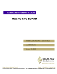
1
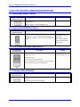
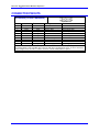
^1 HARDWARE REFERENCE MANUAL
^2 Flex CPU Piggyback Board
^3 CPU
^4 3xx-603605-xHxx
^5 December 8 2003
Single Source Machine Control
Power // Flexibility // Ease of Use
21314 Lassen Street Chatsworth, CA 91311 // Tel. (818) 998-2095 Fax. (818) 998-7807 // www.deltatau.com
Copyright Information
© 2003 Delta Tau Data Systems, Inc. All rights reserved.
This document is furnished for the customers of Delta Tau Data Systems, Inc. Other uses are
unauthorized without written permission of Delta Tau Data Systems, Inc. Information contained
in this manual may be updated from time-to-time due to product improvements, etc., and may not
conform in every respect to former issues.
To report errors or inconsistencies, call or email:
Delta Tau Data Systems, Inc. Technical Support
Phone: (818) 717-5656
Fax: (818) 998-7807
Email: [email protected]
Website: http://www.deltatau.com
Operating Conditions
All Delta Tau Data Systems, Inc. motion controller products, accessories, and amplifiers contain
static sensitive components that can be damaged by incorrect handling. When installing or
handling Delta Tau Data Systems, Inc. products, avoid contact with highly insulated materials.
Only qualified personnel should be allowed to handle this equipment.
In the case of industrial applications, we expect our products to be protected from hazardous or
conductive materials and/or environments that could cause harm to the controller by damaging
components or causing electrical shorts. When our products are used in an industrial
environment, install them into an industrial electrical cabinet or industrial PC to protect them
from excessive or corrosive moisture, abnormal ambient temperatures, and conductive materials.
If Delta Tau Data Systems, Inc. products are directly exposed to hazardous or conductive
materials and/or environments, we cannot guarantee their operation.
Flex CPU Piggyback Board Hardware Reference
Table of Contents
INTRODUCTION .......................................................................................................................................................1
BOARD CONFIGURATION .....................................................................................................................................3
Non-Turbo CPU Base Configuration ...................................................................................................................3
Non-Turbo CPU Further Options.........................................................................................................................3
Turbo CPU Base Configuration ...........................................................................................................................3
Turbo CPU Further Options.................................................................................................................................3
HARDWARE SETUP .................................................................................................................................................5
Flex CPU Board Jumper Configuration...............................................................................................................5
Watchdog Timer Jumper.......................................................................................................................................5
Dual-Ported RAM Source Jumper ........................................................................................................................5
Power-Up State Jumpers ......................................................................................................................................5
Firmware Load Jumper ........................................................................................................................................5
Flash Memory Bank Select Jumpers.....................................................................................................................5
Installation............................................................................................................................................................5
OPERATION OF THE FLEX CPU ..........................................................................................................................7
Operation as Non-Turbo CPU..............................................................................................................................7
Operation as a Turbo CPU...................................................................................................................................9
FLEX CPU BOARD JUMPER DESCRIPTIONS..................................................................................................11
E1: Watchdog Disable Jumper ...........................................................................................................................11
E2: Dual-Ported RAM Port Select......................................................................................................................11
E4 – E6: Power-Up/Reset Load Source..............................................................................................................11
E7: Firmware Reload Enable .............................................................................................................................11
E10A, B, C: Flash Memory Bank Select .............................................................................................................12
CONNECTOR SUMMARY .....................................................................................................................................13
CONNECTOR PINOUTS.........................................................................................................................................15
J8 JRS232 (10-Pin Connector) ...........................................................................................................................15
SCHEMATICS
Table of Contents
i
Flex CPU Piggyback Board Hardware Reference
ii
Table of Contents
Flex CPU Piggyback Board Hardware Reference
INTRODUCTION
The Flex CPU piggyback board (Part # 300-603605-10x) for the PMAC/PMAC2 and Turbo
PMAC/PMAC2 families of boards provides new high-end capabilities for these controllers and uses
newer components with longer product lifetimes. It can be manufactured in a wide variety of
configurations, and can be used in the following products:
•
•
•
•
•
•
•
•
•
•
•
•
PMAC(1)-PC
PMAC(1)-PCI
PMAC(1)-VME
PMAC2-PC
PMAC2-PCI
PMAC2-VME
Turbo PMAC(1)-PC
Turbo PMAC(1)-PCI
Turbo PMAC(1)-VME
Turbo PMAC2-PC
Turbo PMAC2-PCI
Turbo PMAC2-VME
On the regular (non-Turbo) PMAC(1) and PMAC2 boards, the Flex CPU is provided automatically when
any of the following CPU options are ordered:
•
•
•
Option 5AF: 40 MHz CPU with 128k x 24 internal SRAM
Option 5CF: 80 MHz CPU with 128k x 24 internal SRAM
Option 5EF: 160 MHz CPU with 128k x 24 internal SRAM
The Flex CPU board is not provided if Option 4x or 5x is not ordered, or if Option 4A, 5A, 5B, or 5C is
ordered.
On Turbo PMAC(1) and Turbo PMAC2 boards, the Flex CPU may be provided when any of the
following CPU options is ordered:
•
•
•
•
Option 5C0: 80 MHz DSP56303 CPU with 8k x 24 internal SRAM, 256k x 24 external SRAM
Option 5C3: 80 MHz DSP56303 CPU with 8k x 24 internal SRAM, 1M x 24 external SRAM
Option 5D0: 100 MHz DSP56309 CPU with 34k x 24 internal SRAM, 256k x 24 external SRAM
Option 5D3: 100 MHz DSP56309 CPU with 34k x 24 internal SRAM, 1M x 24 external SRAM
In these cases, however, the older Turbo only CPU piggyback board may also be provided.
On Turbo PMAC(1) and Turbo PMAC2 boards, the Flex CPU will be provided automatically when either
of the following CPU options is ordered:
•
•
Option 5E0: 160 MHz DSP56309 CPU with 128k x 24 internal SRAM, 256k x 24 external SRAM
Option 5E3: 160 MHz DSP56309 CPU with 128k x 24 internal SRAM, 1M x 24 external SRAM
Introduction
1
Flex CPU Piggyback Board Hardware Reference
2
Introduction
Flex CPU Piggyback Board Hardware Reference
BOARD CONFIGURATION
Non-Turbo CPU Base Configuration
When assembled for a non-Turbo CPU, the DSP IC in U1 of the Flex CPU board contains all of the
memory required for operation. Therefore, there are no ICs installed in the locations for external RAM:
U11, U12, U13, U14, U15, and U16.
The CPU is available in several speed options: 40 MHz (Option 5AF), 80 MHz (Option 5CF), and 160
MHz (Option 5EF). The maximum frequency of operation is indicated with a sticker on the CPU in U1.
When the Flex CPU is built for ISA-bus or VME-bus baseboards, the P3 connector consists of a 36-pin
header on the solder side for direct connection to the baseboard, and a 10-pin header on the component
side for cable connection of the extra signals required for dual-ported RAM interface. When the Flex
CPU is built for PCI-bus baseboards the P3 connector consists only of a 56-pin header on the solder side
for direct connection of all signals to the baseboard.
Non-Turbo CPU Further Options
The Option 16 battery-backed parameter RAM provides a bank of non-volatile memory for the controller.
Its key components are RAM ICs in U17, U18, and U19, and a battery in BT1
Turbo CPU Base Configuration
When assembled for a Turbo CPU section, the Flex CPU board contains external RAM ICs in locations
U11, U12, U13, U14, U15, U16. With the standard memory configuration (Option 5x0), these ICs fill the
smaller footprint in these locations, leaving an open pin on the board on each end of each side.
When the Flex CPU is built for ISA-bus or VME-bus baseboards, the P3 connector consists of a 36-pin
header on the solder side for direct connection to the baseboard, and a 10-pin header on the component
side for cable connection of the extra signals required for dual-ported RAM interface. When the Flex
CPU is built for PCI-bus baseboards the P3 connector consists only of a 56-pin header on the solder side
for direct connection of all signals to the baseboard.
Turbo CPU Further Options
If an expanded memory configuration (Option 5x3) is ordered, larger RAM ICs are installed in locations
U11, U12, U13, U14, U15, U16, occupying the full footprints in these locations
If the Option 9T auxiliary serial port is ordered for the Turbo PMAC controller, an RS-232 serial port is
provided on the CPU board to supplement the serial port on the baseboard. The key components are ICs
in U28 and U29, and the connector J8.
The Option 16A battery-backed parameter RAM provides a bank of non-volatile memory for the
controller. Its key components are RAM ICs in U17, U18, and U19, and a battery in BT1
Board Configuration
3
Flex CPU Piggyback Board Hardware Reference
4
Board Configuration
Flex CPU Piggyback Board Hardware Reference
HARDWARE SETUP
Flex CPU Board Jumper Configuration
Watchdog Timer Jumper
Jumper E1 on the Turbo CPU board must be OFF for the watchdog timer to operate. This is a very
important safety feature, so it is vital that this jumper be OFF in normal operation. E1 should be put ON
only to debug problems with the watchdog timer circuit.
Dual-Ported RAM Source Jumper
Jumper E2 must connect pins 1 and 2 to access dual-ported RAM (non-Turbo addresses $Dxxx, Turbo
addresses $06xxxx) from the baseboard. If it is desired to use the Option 2 DPRAM on the baseboard,
jumper E2 must be in this setting. All Delta Tau base boards except the PMAC(1)-PC board have the
option for installing DPRAM on the base board.
Jumper E2 must connect pins 2 and 3 to access dual-ported RAM (non-Turbo addresses $Dxxx, Turbo
addresses $06xxxx) through the JEXP expansion port. If it is desired to use DPRAM on an external
accessory board, jumper E2 must be in this setting. The PMAC(1)-PC base board (part # 602191-10x)
does not have the option for installing on-board DPRAM; it requires the external Option 2 DPRAM board
(part #602240-10x) for this functionality. Use of this DPRAM board, interfacing through the JEXP port,
requires E2 to connect pins 2 and 3.
Power-Up State Jumpers
Jumper E4 on the Turbo CPU board must be OFF, jumper E5 must be ON, and jumper E6 must be ON, in
order for the CPU to copy the firmware from flash memory into active RAM on power-up/reset. This is
necessary for normal operation of the card. (Other settings are for factory use only.)
Firmware Load Jumper
If jumper E7 on the CPU board is ON during power-up/reset, the board comes up in “bootstrap mode,”
which permits loading new firmware into the flash-memory IC on the board. When the PMAC Executive
program tries to establish communications with a board in this mode, it will automatically detect that the
board is in bootstrap mode and ask you what file you want to download as the new firmware.
Jumper E7 must be OFF during power-up/reset for the board to come up in normal “operational mode.”
Flash Memory Bank Select Jumpers
The flash-memory IC in location U10 on the Flex CPU board has the capacity for eight separate banks of
firmware, only one of which can be used at any given time. The eight combinations of settings for
jumpers E10A, E10B, and E10C select which bank of the flash memory is used. In the factory production
process, firmware is loaded only into Bank 0, which is selected by having all of these jumpers OFF.
Installation
The Flex CPU board installs on the base controller board using the P1 and P3 stack connectors on the
solder side of the CPU board. The CPU board can be further secured to the base board with a standoff
and screw through the central hole. When a complete PMAC or Turbo PMAC controller is purchased,
this assembly is done at the factory. In the case of retrofits or updates to existing controllers, this
assembly is easy to do in the field.
ESD Warning: The Flex CPU board and PMAC controller boards contain static-sensitive components.
Make sure proper ESD protection is employed.
Hardware Setup
5
Flex CPU Piggyback Board Hardware Reference
6
Hardware Setup
Flex CPU Piggyback Board Hardware Reference
OPERATION OF THE FLEX CPU
Operation as Non-Turbo CPU
When used as a non-Turbo CPU, the Flex CPU board operates in a manner that is fundamentally
compatible with older CPU designs. However, there are a few issues to note:
•
The Flex CPU requires the use of V1.17 or newer firmware. There are few differences between the
previous V1.16H firmware and the V1.17 firmware other than the addition of internal support for the
Flex CPU design.
•
Due to more advanced processor logic and the internal integration of all memory, the Flex CPU will
operate significantly faster than older non-Turbo CPU designs, even for equivalent CPU frequencies.
The Flex CPU in a non-Turbo configuration will generally operate more than twice as fast as older
non-Turbo CPUs running at the same frequency.
This will result in significantly faster cycle times for background tasks such as PLC programs (the
frequency of interrupt-driven foreground tasks is not affected, although the increased computational
speeds permit higher frequencies for these tasks). Generally, this will not be a problem, but if
existing programs controlled timing by computational delay (e.g. number of loops waiting),
operational differences may occur.
•
The operational frequency of the CPU can now be set in software by new variable I46. If this
variable is set to 0, PMAC firmware looks at the jumpers (E48 on a PMAC(1), E2 and E4 on a
PMAC2) to set the operational frequency, retaining backward compatibility for 40, 60, and 80 MHz
operation.. If I46 is set to a value greater than 0, the operational frequency is set to 10MHz * (I46 +
1), regardless of the jumper setting. If the desired operational frequency is higher than the maximum
rated frequency for that CPU, the operational frequency will be reduced to the rated maximum. It is
always possible to operate the Flex CPU board at a frequency below its rated maximum.
On a Flex CPU board configured for Option 5AF with 40 MHz maximum frequency, I46 should be
set to 3 to operate the CPU at its maximum rated frequency.
On a Flex CPU board configured for Option 5CF with 80 MHz maximum frequency, I46 should be
set to 7 to operate the CPU at its maximum rated frequency.
On a Flex CPU board configured for Option 5EF with 160 MHz maximum frequency, I46 should be
set to 15 to operate the CPU at its maximum rated frequency.
I46 is only used at power-up/reset, so to change the operational frequency, set a new value of I46,
issue a SAVE command to store this value in non-volatile flash memory, then issue a $$$ command
to reset the controller.
To determine the frequency at which the CPU is actually operating, issue the TYPE command to the
PMAC. The PMAC will respond with five data items, the last of which is CLK Xn, where n is the
multiplication factor from the 20 MHz crystal frequency (not 10 MHz). n should be equivalent to
(I46+1)/2 if I46 is not requesting a frequency greater than the maximum rated for that CPU board. n
will be “2” for 40 MHz operation, 4 for 80 MHz operation, and 8 for 160 MHz operation.
•
If the CPU’s operational frequency has been determined by (a non-zero setting of) I46, the serial
communications baud rate is determined at power-up/reset by variable I54 alone according to the
following table:
Operation of the Flex CPU
7
Flex CPU Piggyback Board Hardware Reference
I54
Baud Rate
I54
Baud Rate
0
1
2
3
4
5
6
7
600
900
1200
1800
2400
3600
4800
7200
8
9
10
11
12
13
14
15
9600
14,400
19,200
28,800
38,400
57,600
76,800
115,200
Note that these values can be different from those used on PMAC2 boards with jumper-set CPU
frequencies (see below).
•
If the saved value of I46 is 0, so the CPU’s operational frequency is determined by jumper settings,
then the serial baud rate is determined by a combination of the setting of jumpers E44-E47 and the
CPU frequency on a PMAC(1) board, as shown in the following table. These settings maintain
backward compatibility.
E44
E45
E46
N
ON
ON
OFF
ON
ON
ON
OFF
ON
OFF
OFF
ON
ON
ON
OFF
OFF
ON
OFF
ON
OFF
OFF
OFF
OFF
OFF
ON
ON
ON
OFF
ON
ON
ON
OFF
ON
OFF
OFF
ON
ON
ON
OFF
OFF
ON
OFF
ON
OFF
OFF
OFF
OFF
OFF
* Not an exact baud rate
8
E47
ON
ON
ON
ON
ON
ON
ON
ON
OFF
OFF
OFF
OFF
OFF
OFF
OFF
OFF
Baud Rate
for
20MHz
Baud Rate
for
40MHz
Baud Rate
for
60MHz
Disabled
300
400*
600
800*
1200
1600*
2400
3200*
4800
6400*
9600
12800*
19200
25600*
38400
Disabled
600
800*
1200
1600*
2400
3200*
4800
6400*
9600
12800*
19200
25600*
38400
51200*
76800
Disabled
900
1200
1800
2400
3600
4800
7200
9600
14400
19200
28800
38400
57600
76800
115200
Operation of the Flex CPU
Flex CPU Piggyback Board Hardware Reference
For a PMAC2 board with a saved value of 0 for I46, the serial baud rate is determined by the combination
of I54 and the CPU frequency on a PMAC2 board as shown in the following table. These settings
maintain backward compatibility.
I54
Baud Rate for
40 MHz CPU
0
600
1
900* (-0.05%)
2
1200
3
1800* (-0.1%)
4
2400
5
3600* (-0.19%)
6
4800
7
7200* (-0.38%)
8
9600
9
14,400*(-0.75%)
10
19,200
11
28,800*(-1.5%)
12
38,400
13
57,600*(-3.0%)
14
76,800
15
Disabled
* Not an exact baud rate
•
Baud Rate for
60 MHz CPU
Disabled
900
1200
1800
2400
3600
4800
7200
9600
14,400
19,200
28,800
38,400
57,600
76,800
115,200
Baud Rate for
80 MHz CPU
1200
1800* (-0.1%)
2400
3600* (-0.19%)
4800
7200* (-0.38%)
9600
14,400*(-0.75%)
19,200
28,800*(-1.5%)
38,400
57,600*(-3.0%)
76,800
115,200*(-6.0%)
153,600
DISABLED
With the Flex CPU, the card number (0 – 15) for serial addressing of multiple cards on a daisy-chain
serial cable is determined by variable I0, even on PMAC(1) boards. This has always been the case
for PMAC2 boards, but with other CPU boards, the card number on PMAC(1) boards has been
determined by the settings of jumpers E40 – E43. Jumpers E40 – E43 on a PMAC(1) board with the
Flex CPU still determine the “direction” of the phase and servo clocks: all of these jumpers must be
ON for the card to use its internally generated clock signals and to output these on the serial port
connector; if any of these jumpers is OFF, the card will expect to input these clock signals from the
serial port connector, and its watchdog timer will trip immediately if it does not receive these signals.
Operation as a Turbo CPU
When used as a Turbo CPU, the Flex CPU is fully compatible with older CPU designs. It does permit
higher-speed configurations (Option 5Ex at 160 MHz), which offer significantly higher performance both
due to increased operation frequency and added internal memory.
Variable I52 determines the actual operating frequency of the Turbo CPU. The operational frequency is
set to 10MHz * (I52 + 1). I52 should be set to 7 to operate an Option 5Cx board at its maximum rated
frequency of 80 MHz; it should be set to 9 to operate an Option 5Dx board at its maximum rated
frequency of 100 MHz; it should be set to 15 to operate an Option 5Ex board at is maximum rated
frequency of 160 MHz.
I52 is used only at power-up/reset, so to change the operational frequency, set a new value of I52, issue a
SAVE command to store this value in non-volatile flash memory, then issue a $$$ command to reset the
controller.
Operation of the Flex CPU
9
Flex CPU Piggyback Board Hardware Reference
10
Operation of the Flex CPU
Flex CPU Piggyback Board Hardware Reference
FLEX CPU BOARD JUMPER DESCRIPTIONS
E1: Watchdog Disable Jumper
E Point and
Physical Layout
E1
Description
Jump pin 1 to 2 to disable Watchdog timer (for test
purposes only).
Remove jumper to enable Watchdog timer.
Default
No jumper installed
E2: Dual-Ported RAM Port Select
E Point and
Physical Layout
E2
Description
Jump pin 1 to 2 to access DPRAM from baseboard.
Jump pin 2 to 3 to access DPRAM through JEXP
expansion port (PMAC(1)-PC with Option 2 DPRAM
board).
Default
Pins 2 and 3 jumpered
(with PMAC(1)-PC base
board only)
Pins 1 and 2 jumpered
(when used on all other
base boards)
E4 – E6: Power-Up/Reset Load Source
E Point and
Physical Layout
Description
Default
E6
Remove jumper E4;
jump E5 pin 1 to 2;
jump E6 pin 2 to 3;
to read flash IC on power-up/reset
Other combinations are for factory use only; the board
will not operate in any other configuration.
No E4 jumper installed;
E5 and E6 jump pin 1 to 2
E4
E7: Firmware Reload Enable
E Point and
Physical Layout
E7
Description
Jump pin 1 to 2 to reload firmware through serial or
bus port.
Remove jumper for normal operation.
Flex CPU Board Jumper Descriptions
Default
No jumper installed
11
Flex CPU Piggyback Board Hardware Reference
E10A, B, C: Flash Memory Bank Select
E Point and
Physical Layout
E10A
Description
Default
Remove all 3 jumpers to select flash memory bank
with factory-installed firmware.
Use other configuration to select one of the 7 other
flash memory banks
No jumpers installed
E10C
12
Flex CPU Board Jumper Descriptions
Flex CPU Piggyback Board Hardware Reference
CONNECTOR SUMMARY
J2: JEXP Expansion Port (50-pin IDC header for Delta Tau accessory boards)
J5: JTAG/OnCE Port (for factory use only)
J6: JSIO Port (for factory use only)
J7: JISP Port (for factory use only)
J8: Auxiliary Serial Port (10-pin IDC header)*
P1: Stack Connector (Internal connections to main PMAC board)
P3: Stack Connector (Internal connections to main PMAC board)
*Pinout shown in next section
Connector Summary
13
Flex CPU Piggyback Board Hardware Reference
14
Connector Summary
Flex CPU Piggyback Board Hardware Reference
CONNECTOR PINOUTS
J8 JRS232 (10-Pin Connector)
Front View
Pin #
Symbol
Function
Description
Notes
1
N.C.
No Connect
2
DTR
Bidirect
Data Terminal Ready
Tied to DSR
3
TXD/
Input
Receive Data
Host transmit data
4
CTS
Input
Clear to Send
Host ready bit
5
RXD/
Output
Send Data
Host receive data
6
RTS
Output
Request to Send
PMAC ready bit
7
DSR
Bidirect
Data Set Ready
Tied to DTR
8
N.C.
No Connect
9
GND
Common
PMAC Common
10
+5V
Output
+5VDC Supply
Power supply out
The JRS232 connector provided with Option 9T on a Turbo PMAC is an auxiliary serial port that can be
used independently of the standard main serial port and other communications ports. It can be connected
with a straight-across flat cable to a DB-9 connector with the standard RS-232 pinout.
Connector Pinouts
15
C24
(jisp)
J7
+3P3V
.1UF
1
2
3
4
TMS
GND
TCK
RDBA05
RDFLASHCSBSCAN-
BA06
BA07
BA08
BA09
PRAMCS-
6
7
8
C25
BA10
BA11
.1UF
BA12
BA13
+3P3V
WR-
HSIP8NO5
C21
.01UF
BA14
BA15
GND
OE1
A0
A1
GND
A2
A3
VCC
A4
A5
GND
A6
A7
A8
A9
GND
A10
A11
VCC
A12
A13
GND
A14
A15
OE2
BA12
BA13
10
.1UF
10KSIP10C
+3P3V
BA14
BA15
+3P3V
GUARD BAND
1
2
3
4
5
6
7
8
9
10
11
12
13
14
15
16
17
18
19
20
21
22
23
24
T/R1
B0
B1
GND
B2
B3
VCC
B4
B5
GND
B6
B7
B8
B9
GND
B10
B11
VCC
B12
B13
GND
B14
B15
T/R2
BRTSTMS
BGT/RBSTD1
BSRD1
BSCK1
BSC12
GUARD BAND
EXTAL
BHACKBX/Y
BWR-
BRDBA05_A
BA06_A
BA07_A
BA08_A
BA09_A
*NETLIST CHANGE*
********
+3P3V
C27
BX/Y
BWR-
BRDBA05_A
GUARD BAND
TP1
GND
.1UF
E4
E5
E6
E7
+3P3V
BA14_A
BA15_A
GND
74LCX16245
(TSSOP48)
GND
POLY
**POLY CAP**
BA12_A
BA13_A
BA14_A
BA15_A
.47UF
.1UF
+3P3V
C26
BA10_A
BA11_A
BA12_A
BA13_A
C43
.001
(0805)
C42
GND
BA06_A
BA07_A
BA08_A
BA09_A
BA10_A
BA11_A
F1
C41
.1UF
EXTAL
55FZ103N
VCCQL
2
E4
1
2
E5
1
2
E6
1
2
E7
1
+5V
U6
H0
H1
H2
H3
H4
H5
H6
H7
HR/W
HDSA3
A4
A5
A6
A7
A8
A9
A10
A11
A12
A13
A14
A15
A16
A17
RDWRPRAMCSDRAMCSFLASHCSCPUCLK
SEL
RESETBSCAN-
B
GUARD BAND
PRAMCSDRAMCSFLASHCS-
86
17
29
33
55
46
57
70
59
31
80
56
3
71
73
8
4
79
90
6
84
9
82
78
54
39
60
37
20
16
11
7
15
14
66
87
65
62
10
26
1
24
52
75
27
49
2
13
25
38
+3P3V
1
3
C83
.1UF
GND
C84
.1UF
E2
C85
.1UF
2
C86
.1UF
H0
H1
H2
H3
H4
H5
H6
H7
HRW
HDSA3
A4
A5
A6
A7
A8
A9
A10
A11
A12
A13
A14
A15
A16
A17
RD-/TDO
WR-/TCK
PRAMCS-/TMS
DRAMCSPROMCS-/TDI
CPUCLK/Y0
SEL
RESETBSCANGOE0
GOE1
Y1
Y2
N.C.
N.C.
VCCIO
VCCIO
VCCIO
VCCIO
N.C.
N.C.
GND
GND
GND
GND
BH0
BH1
BH2
BH3
BH4
BH5
BH6
BH7
BHRW
BHDSLA12
LA13
PA16
PA17
PA18
PA19
PA20
PA21
VMECSDPRCSBBRCSIOCS0IOCS1VCC
VCC
N.C.
N.C.
CS0CS1CS2CS3CS4N.C.
N.C.
N.C.
N.C.
CS00CS04CS06CS10CS12CS14CS16BRCLK
WDTC
N.C.
GND
GND
GND
GND
ISPLSI2064E_DECODE
(TSOP100)
E2 1-to-2 is for DPR on base board
E2 2-to-3 is for DPR on expansion board
85
68
36
23
18
53
44
21
81
83
5
92
91
98
94
95
96
97
69
34
72
35
30
64
12
100
99
43
40
28
19
22
89
77
76
61
32
58
47
45
48
42
41
93
67
50
88
74
63
51
BH0
BH1
BH2
BH3
BH4
BH5
BH6
BH7
BHR/W
BHDSLA12
LA13
PA16
PA17
PA18
PA19
PA20
PA21
BBRAMCSIOCS_AIOCS_B-
2
3
4
5
6
7
8
9
U1
DSP56311GC150
RP2
1
+3P3V
GND
X/Y:$000000-$0107FF STANDARD MEMORY OPTION (64K)
X/Y:$000000-$03FFFF EXTENDED MEMORY OPTION (256K)
P:$000000-$0FFFFF
.1UF
MAX3100CEE
(QSOP)
TP2
R3
SIRQ-
1K
Y2
C70
ECS-36-20-5P
3.6864Mhz
22pf
GND
16
VCC
C2+
4
3
C1-
C2-
5
11
TXD
TXD
14
12
RXD
RXD
13
10
RTS
RTS
7
9
CTS
CTS
8
.1UF
D
HEADER 10
(BOX)
C71
MAX3232ECWE
(SOL16)
22pf
GUARD BANDING REQ'D
C36
GND
+5V
.1UF
U4A
R2
INIT-
U4B
1
2
C1
.1UF
U4C
3
4
10K
5
(SO14)
74ACT14
74ACT14
(SO14)
Q4
3
SOT23
2N7002
(SOT23)
GND
C35
WDTC
1
RP5A
2
3
1KSIP6I
.01UF
RP5B
RESET
6
(SO14)
74ACT14
Q5 3
2N7002
SOT23
(SOT23)
C
4
1KSIP6I
+5V
D3
BB-
1
RP5C
1KSIP6I
3
MMBD301LT1
3
2
Q1
MMBT3906LT1
(SOT23)
U3
1
2
3
4
5
6
7
8
+ C34
1UF
35V
tant
R4
100K
E1
GND
U4D
N.C.
VCC
N.C.
NMI
N.C.
RST
N.C.
RST
N.C.
IN
N.C.
MODE
N.C.
TOL
N.C.
GND
16
15
14
13
12
11
10
9
9
WDO
8
(SO14)
74ACT14
U4E
C2
DS1231S
(SOL16)
11
10
.1UF
(SO14)
74ACT14
D4
1
3
D2
LED
GRN
PWR
10
3.3KSIP10C
Vbat
+3P3V
+5V
D2A
LED
GRN
PWR
D1
LED
RED
WD
D1A
LED
RED
WD
C33
LA12
LA13
PA16
PA17
PA18
PA19
PA20
PA21
*NETLIST CHANGE*
*NETLIST CHANGE*
1
Memory Range
P:$D00000-$D3FFFF (MAXIMUM OF 16 BANKS)
X/Y:$050000-$053FFF STANDARD MEMORY OPTION (16K)
X/Y:$050000-$05FFFF EXTENDED MEMORY OPTION (64K)
2
C102
C105
.1UF
BRCLK
RP1_9
GND
C103
U25
48
47
46
45
44
43
42
41
40
39
38
37
36
35
34
33
32
31
30
29
28
27
26
25
GND
GND
CLK
4
OE1
A0
A1
GND
A2
A3
VCC
A4
A5
GND
A6
A7
A8
A9
GND
A10
A11
VCC
A12
A13
GND
A14
A15
OE2
T/R1
B0
B1
GND
B2
B3
VCC
B4
B5
GND
B6
B7
B8
B9
GND
B10
B11
VCC
B12
B13
GND
B14
B15
T/R2
PI74FCT16245ATA
(TSSOP48)
.1UF
1
2
3
4
5
6
7
8
9
10
11
12
13
14
15
16
17
18
19
20
21
22
23
24
4
7
CS0CS1CS2CS3CS4CS00CS04CS06CS10CS12CS14CS16VMECSDPRCS-
X/Y:$078000-$0780FF
X/Y:$078100-$0781FF
CS0CS1-
GND
N.C.
VCC
CLK
11
CLK
8
GND
VMECSDPRCS-
WDTC
1
3
MMBD301LT1
GND
1
13
R1
12
3
.01FARAD
FM0H103Z
NEC
VOUT
BATT
8
2
VCC
RST
7
RESET-
3
ON
CEO
6
BBRCS-
CEI
5
BBRAMCS-
GND
MAX795SCSA
(SO8)
C16
.1UF
C17
WAIT1-
1
WAIT2-
2
NC7SZ00
(SOT23-5)
3
SOT23
.1UF
4
Q2
2N7002
(SOT23)
U30
BSTD1
BSRD1
BSCK1
BSC12
BSC11
BTXD
BRTSBHREQ-
+5V
TA-
2
3
4
5
6
7
8
9
1
19
RP8
3.3KSIP10C
RP7
3.3KSIP10C
GND
BBRCSB
P1
B0
B1
B2
B3
B4
B5
B6
B7
18
17
16
15
14
13
12
11
VCC
GND
20
10
A0
A1
A2
A3
A4
A5
A6
A7
T/R
OE
PI74FCT245TL
(TSSOP20)
RP9A
330SIP8I
1
3
5
7
2
4
6
8
R8
330
STD1
SRD1
SCK1
SC12
SC11
TXD
RTSHREQ-
C88
.1UF
GND
P1
U26C
GND
RESET-
5
6
74ACT14
(SO14)
+5V
.1UF
U24A
1
BWR-
2
BWR_A-
3
+3P3V
BWR_A-
1
RP4
10
IOCS_A-
74ACT32
(SO14)
U24B
3.3KSIP10C
4
BRD-
BRD_A-
6
5
BRD_ABRXD
BCTSSER_A
PHA_A
BHA2
BHA1
BHA0
MODD/IRQD-
2
3
4
5
6
7
8
9
A
74ACT32
(SO14)
IOCS_BBWR-
Firmware (64K)
User Written Phase (1K)
User Written Servo (2K)
Plcc Standard Memory Option (64K)
Plcc Extended Memory Option (448K)
U24C
9
BWR_B-
8
10
BWR_B-
T/RRESET
74ACT32
(SO14)
12
BRD_B-
11
13
B0
B1
B2
B3
B4
B5
B6
B7
18
17
16
15
14
13
12
11
VCC
GND
20
10
A0
A1
A2
A3
A4
A5
A6
A7
1
19
T/R
OE
2
4
6
8
10
12
14
16
18
20
22
24
26
28
30
32
34
36
CS4WAIT1U26A
1
GND
1SMC5.0AT3
U26B
2
3
4
74ACT14
(SO14)
74ACT14
(SO14)
U26F
U26E
13
12
11
.1UF
BPHA
A
BPHA
C82
+5V
GND
.1UF
10
74ACT14
(SO14)
C87
GUARD BANDING REQ'D
19.6608Mhz
WDO
HACKRXD
TXD
CTSSTD1
SRD1
SCK1
SC12
SC11
IRQB-
VSP01VT18A01
D7
RXD
CTSBSER
BPHA
HA2
HA1
HA0
IRQB-
74LCX245
(TSSOP20)
U24D
BRD-
WAIT2-
U27
2
3
4
5
6
7
8
9
1
3
5
7
9
11
13
15
17
19
21
23
25
27
29
31
33
35
INITRESET_A
HA2
HA1
HA0
HR/W
HDSHREQH7
H6
H5
H4
H3
H2
H1
H0
BSER
BSER
74ACT14
(SO14)
U26D
BRD_B9
GND
74ACT32
(SO14)
RESET_B
8
Delta Tau Data Systems, Inc.
RESET_B
Title
74ACT14
(SO14)
|Link
|605-1sh2.sch
Size
D
Date:
7
RESET-
+5V
GND
*NETLIST CHANGE*
********
C40
WAIT2-
C15
.1UF
+3P3V
U9
R6A
1K
TRST-
19.6608Mhz
10
(SO14)
74ACT14
R6
1K
1
4
MMBD301LT1
19.6608Mhz
R5A
1K
U2
(SOT23)
U4F
X/Y:$078E00-$078EFF
X/Y:$078F00-$078FFF
X/Y:$078F00-$078FFF
X/Y:$060000-$060FFF STANDARD MEMORY OPTION (4K)
X/Y:$060000-$063FFF EXTENDED MEMORY OPTION (16K)
X/Y:$060000-$06FFFF EXTENDED MEMORY OPTION (64K)
X/Y:$070000-$077FFF
CS14CS16-
D5
+1
R5
1K
2
D6
19.6608MHz
(DIP14WIDE)
X/Y:$078A00-$078AFF
X/Y:$078B00-$078BFF
X/Y:$078C00-$078CFF
X/Y:$078D00-$078DFF
CS04CS06CS10CS12-
3
MMBT3906LT1
GUARD BAND
14
X/Y:$078400-$0787FF
X/Y:$078800-$0789FF
CS4CS00-
2
3.6V BAT
X/Y:$078200-$0782FF
X/Y:$078300-$0783FF
CS2CS3-
BT1
R7
100
CPUCLK
3
Q3
Vout
Vout
GUARD BAND
Y1B
.1UF
.1UF
.1UF
VCC
MHR13FAJ19.6608
(4 PIN SMT)
1
C100
N.C.
+5V
C101
IOCS_AIOCS_B-
*DUAL FOOTPRINT*
Y1A .1UF
C20
8
J8 (JRS232)
N.C.
1
DTR
2
TXD3
CTS
4
RXD5
RTS
6
DSR
7
N.C.
8
GND
9
+5V
10
VSS
16
15
14
13
12
11
10
9
VCC
TX
RX
RTS
N.C.
CTS
X1
X2
MMBD301LT1
GND
PRAM MEMORY P:
$000000-$00FFFF
$040000-$0403FF
$040400-$040BFF
$050000-$05FFFF
$050000-$0BFFFF
SIRQ-
DIN
DOUT
SCLK
CS
N.C.
IRQ
SHDN
GND
C1+
.1UF
C75
15
D0
D1
D2
D3
D4
D5
D6
D7
D8
D9
D10
D11
D12
D13
D14
D15
D16
D17
D18
D19
D20
D21
D22
D23
A0
A1
A2
A3
A4
A5
A6
A7
A8
A9
A10
A11
A12
A13
A14
A15
A16
A17
RDWR-
E14
D12
D13
C13
C14
B13
C12
A13
B12
A12
B11
A11
C10
B10
A10
B9
A9
B8
C8
A8
B7
B6
C6
A6
N14
M13
M14
L13
L14
K13
K14
J13
J12
J14
H13
H14
G14
G12
F13
F14
E13
E12
M12
M11
N11
P11
L11
L10
L9
L8
L7
D0
D1
D2
D3
D4
D5
D6
D7
D8
D9
D10
D11
D12
D13
D14
D15
D16
D17
D18
D19
D20
D21
D22
D23
A0
A1
A2
A3
A4
A5
A6
A7
A8
A9
A10
A11
A12
A13
A14
A15
A16
A17
RDWRBRBBGND
GND
GND
GND
GND
E1
GND
MODA/IRQAMODB/IRQBMODC/IRQCBOOTENSC01
SIRQBTXD
BSC11
H0
H1
H2
H3
H4
H5
H6
H7
HA0
HA1
HA2
HCSHDSHRW
HACKHREQRXD
TXD
SRD0
STD0
SC00
SC10
SCK0
SCK1
SCLK
TIO0
TIO1
TIO2
BGAA0
AA1
AA2
AA3
CASXTAL
EXTAL
CLKOUT
BCLK
BCLKVCCP
PCAP
GNDP
GNDP1
GND
GND
GND
GND
GND
GND
GND
GND
1
2
3
4
5
6
7
8
1
6
J8
+5V
C74
V-
1
+3.3V
TDO
TDI
BSCAN-
A19X/YP
WR-
+3P3V
J7
48
47
46
45
44
43
42
41
40
39
38
37
36
35
34
33
32
31
30
29
28
27
26
25
+3P3V
C28
BA10
BA11
BA14
BA15
RP6
1
GND
D0
D1
D2
D3
D4
D5
D6
D7
D8
D9
D10
D11
D12
D13
D14
D15
D16
D17
D18
D19
D20
D21
D22
D23
.1UF
U28
STD0
SRD0
SCK0
SC02
+V
2
CPUCLK
HACK-
BA10
BA11
2
3
4
5
6
7
8
9
10KSIP10C
BA06
BA07
BA08
BA09
BA12
BA13
74LCX16245
(TSSOP48)
U8
GUARD BAND
HEA_SIP 8
(.100 MOLEX)
JUMP `J6' PIN 6 TO 7
TO LOAD `isp' PART
BA06
BA07
BA08
BA09
.1UF
D0
D1
D2
D3
D4
D5
D6
D7
D8
D9
D10
D11
D12
D13
D14
D15
D16
D17
D18
D19
D20
D21
D22
D23
2
10
A14
A15
BA04
BA05
10
VCCQL
.1UF
C73
C32
1
A10
A11
A12
A13
+3P3V
TXD
RXD
CTSRTSINIT-
BA04
BA05
.1UF
U29
2
3
4
5
6
7
8
9
C23
.1UF
+5V
1
2
3
4
5
6
7
8
+3P3V
C29
BA02
BA03
55FZ103N
1
(jsio)
J6
BA00
BA01
SC02
BHREQDE*NETLIST CHANGE*
********
SRD0
STD0
SCK0
BB-
NOTE1:
.1UF
1
A6
A7
A8
A9
BA00
BA01
BA02
BA03
2
3
4
5
6
7
8
9
.1UF
C6
6
.1UF
A4
A5
1
.1UF
C5
10
DETRST-
1
2
3
4
5
6
7
8
9
10
11
12
13
14
15
16
17
18
19
20
21
22
23
24
T/R1
B0
B1
GND
B2
B3
VCC
B4
B5
GND
B6
B7
B8
B9
GND
B10
B11
VCC
B12
B13
GND
B14
B15
T/R2
M5
P4
N4
P3
N3
P2
N1
N2
M3
M1
M2
L1
J3
J2
J1
K2
F1
G3
E3
E1
F3
F2
H3
G1
G2
L3
L2
K3
P13
N13
P12
P7
N7
N8
P8
M8
M9
N10
M10
M6
P5
N6
P6
D4
D5
D6
D7
D8
D9
D10
D11
C4
C76
C72
9
8
7
6
5
4
3
2
A2
A3
+3P3V
OE1
A0
A1
GND
A2
A3
VCC
A4
A5
GND
A6
A7
A8
A9
GND
A10
A11
VCC
A12
A13
GND
A14
A15
OE2
.1UF
5
A0
A1
C22
48
47
46
45
44
43
42
41
40
39
38
37
36
35
34
33
32
31
30
29
28
27
26
25
RP3
C14
.1UF
1
U7
RESETTMS
J6
BH0
BH1
BH2
BH3
BH4
BH5
BH6
BH7
BHA0
BHA1
BHA2
MODD/IRQDBHDSBHR/W
BHACKBHREQBRXD
BTXD
SRD0
STD0
BOOTENBRTSSCK0
BSCK1
BRCLK
PHA_A
SER_A
BCTSBGA19X/YP
FLASHCSDRAMCSPRAMCS-
GND
+3P3V
TCK
C3
.1UF
GND
C13
.1UF
F2
C104
DS2415P
(TSOC)
(Request 6pf load capacitance)
(See layout instructions)
TDO
GND
C
10UF
16V
(TANT)
C12
.1UF
2
GND
+
1
2
3
GND
DATA
VDD
C11
.1UF
1
TDI
(SOT-223)
+
X2
X1
VBAT
C10
.1UF
THIS PART MUST BE `MAX3232ECWE'
TO PROVIDE `ESD' PROTECTION
OF THE `RS232' INPUT SECTION.
3
PRDY
C38
6
5
4
Vbat
C9
.1UF
NOTE:
2
GND
PRDY
C37
10UF
16V
(TANT)
HEADER14_NO8
+5V
TXD
RXD
CTSRTSINITGND
N.C.
U5
2
1
RP1_9
2
3
4
5
6
7
8
9
J5
(JTAG/OnCE)
J5
TSI
1
GND
2
TSO
3
GND
4
TCK
5
GND
6
N.C.
7
RST9
TMS
10
+3.3V
11
N.C.
12
DE13
TRST14
+3P3V
C8
.1UF
1
+3P3V
1
OR
3.3KSIP10C
D
Y3
C-002RX
32.768Khz
C7
.1UF
5
10
+5V
INSTALL
`VR1,C89,C90,R11,R12'
FOR `DSP56309PW80'
AND `DSP56311GC150'
DO NOT INSTALL `F2'
NOTE2:
GND
VR1
LM1117MPX-3.3
MC33269ST-3.3
3 IN
OUT
RESET*NETLIST CHANGE*
PINIT
TRSTMODD/IRQDMODC/IRQCMODB/IRQBMODA/IRQADETATMS
TCK
TDO
TDI
BSC12
BSC11
BSTD1
BSRD1
SC02
SC01
2
1
NOTE2:
GND
1
+3P3V
RP1
*
+
10UF
16V
(TANT)
A0
A1
A2
A3
A4
A5
A6
A7
A8
A9
A10
A11
A12
A13
A14
A15
A16
A17
A19X/YP
WRRD-
1
C90
(SOT-223)
+
A1
P1
M4
E2
K1
A14
F12
H1
M7
B14
A7
C9
C11
D14
H12
K12
L12
N12
P9
P14
C7
G13
H2
N9
C89
10UF
16V
(TANT)
2
A0
A1
A2
A3
A4
A5
A6
A7
A8
A9
A10
A11
A12
A13
A14
A15
A16
A17
A19X/YP
WRRD-
+3P3V
INSTALL `F2' ONLY
FOR `DSP56303PW80'
DO NOT INSTALL
`VR1,C89,C90,R11,R12'
FOR `DSP56303PW80'
NOTE1:
3
N.C.
N.C.
VCCH
VCCS
VCCS
N.C.
VCCQH
VCCQH
VCCQH
N.C.
VCCD
VCCD
VCCD
VCCD
VCCA
VCCA
VCCA
VCCC
VCCC
N.C.
VCCQL
VCCQL
VCCQL
VCCQL
VCCQL
2
4
D2
C1
B1
C2
A2
B2
B3
A4
C3
A3
P10
D3
C4
A5
C5
B5
B4
D1
N5
VR2
LM1117MPX-1.8
MC33269ST-1.8
3 IN
OUT
5
GND
GND
GND
GND
GND
GND
GND
GND
GND
GND
GND
GND
GND
GND
GND
GND
GND
GND
GND
GND
GND
GND
GND
GND
GND
GND
GND
GND
GND
GND
GND
GND
GND
GND
GND
GND
GND
GND
GND
GND
GND
GND
GND
GND
GND
GND
GND
GND
GND
GND
GND
OR
GND
+5V
6
SC01
SC02
SRD1
STD1
SC11
SC12
TDI
TDO
TCK
TMS
TA
DE
IRQA
IRQB
IRQC
IRQD
TRST
PINT
RESET
7
E4
E5
E6
E7
E8
E9
E10
E11
F4
F5
F6
F7
F8
F9
F10
F11
G4
G5
G6
G7
G8
G9
G10
G11
H4
H5
H6
H7
H8
H9
H10
H11
J4
J5
J6
J7
J8
J9
J10
J11
K4
K5
K6
K7
K8
K9
K10
K11
L4
L5
L6
8
THIS DOCUMENT IS THE CONFIDENTIAL PROPERTY OF DELTA TAU
DATA SYSTEMS INC. AND IS LOANED SUBJECT TO RETURN UPON
DEMAND. TITLE TO THIS DOCUMENT IS NEVER SOLD OR
TRANSFERRED FOR ANY REASON. THIS DOCUMENT IS TO BE USED
ONLY PURSUANT TO WRITTEN LICENSE OR WRITTEN INSTRUCTIONS
OF DELTA TAU DATA SYSTEMS INC. ALL RIGHTS TO DESIGNS AND
INVENTIONS ARE RESERVED BY DELTA TAU DATA SYSTEMS INC.
POSSESSION OF THIS DOCUMENT INDICATES ACCEPTANCE OF THE
ABOVE AGREEMENT.
6
5
4
3
2
DSP563XX CPU Piggyback Board
Document Number
Rev
-
603605-322P
Thursday, September 19, 2002
1
Sheet
1
of
2
8
7
6
5
THIS DOCUMENT IS THE CONFIDENTIAL PROPERTY OF DELTA TAU
DATA SYSTEMS INC. AND IS LOANED SUBJECT TO RETURN UPON
DEMAND. TITLE TO THIS DOCUMENT IS NEVER SOLD OR
TRANSFERRED FOR ANY REASON. THIS DOCUMENT IS TO BE USED
ONLY PURSUANT TO WRITTEN LICENSE OR WRITTEN INSTRUCTIONS
OF DELTA TAU DATA SYSTEMS INC. ALL RIGHTS TO DESIGNS AND
INVENTIONS ARE RESERVED BY DELTA TAU DATA SYSTEMS INC.
POSSESSION OF THIS DOCUMENT INDICATES ACCEPTANCE OF THE
ABOVE AGREEMENT.
A0
A1
A2
A3
A4
A5
A6
A7
A8
A9
A10
A11
A12
A13
A14
A15
A16
A17
A19X/YP
"E10" FLASH BANK SELECT
D0
D1
D2
D3
D4
D5
D6
D7
D8
D9
D10
D11
D12
D13
D14
D15
D16
D17
D18
D19
D20
D21
D22
D23
+3p3V
R15
3.3K
1
1
E10A
E10B
E10C
R16
3.3K
R17
3.3K
2
2
2
*NETLIST CHANGE*
U10
C
RESETBA11
BA10
BA09
BA08
RESET-
BA07
BA06
BA05
BA04
BA03
BA02
BA01
W1
SOLDER
JUMPER
1
3
W1
1
2
3
4
5
6
7
8
9
10
11
12
13
14
15
16
17
18
19
20
21
22
23
24
25
26
27
28
FLASHCSPA21
PA20
PA19
PA18
PA17
PA16
+3P3V/+5V
BA15
BA14
BA13
BA12
FLASHCSPA21
PA20
PA19
PA18
PA17
PA16
2
C77
.1UF
3
U11 (400MIL)
A22
CE1A21
A20
A19
A18
A17
A16
VCC
A15
A14
A13
A12
CE0
VPEN
RPA11
A10
A09
A08
GND
A07
A06
A05
A04
A03
A02
A01
A24_WP
WEOESTS
DQ15
DQ7
DQ14
DQ6
GND
DQ13
DQ5
DQ12
DQ4
VCCQ
GND
DQ11
DQ3
DQ10
DQ2
VCC
DQ9
DQ1
DQ8
DQ0
A00
BYTEA23
CE2
56
55
54
53
52
51
50
49
48
47
46
45
44
43
42
41
40
39
38
37
36
35
34
33
32
31
30
29
BWRBRDPRDY
A0
A1
A2
A3
A4
A5
A6
A7
A8
A9
A10
A11
A12
A13
A14
A15
A16
A17
D6
BA00
BA01
BA02
BA03
BA04
BA05
BA06
BA07
BA08
BA09
BA10
BA11
BA12
BA13
BA14
BA15
BX/Y
D5
D4
D3
D2
+3P3V/+5V
D1
D0
BA00
D0
D1
D2
D3
D4
D5
D6
D7
D8
D9
D10
D11
D12
D13
D14
D15
D16
D17
D18
D19
D20
D21
D22
D23
6
31
13
18
1
35
34
33
32
24
23
22
21
20
17
16
15
14
5
4
3
2
RDWRA17
A16
A15
A14
A13
A12
A11
A10
A9
A8
A7
A6
A5
A4
A3
A2
A1
A0
A19X/YP
VCC
CE
OE
WE
A18
A17
A16
A15
A14
A13
A12
A11
A10
A9
A8
A7
A6
A5
A4
A3
A2
A1
A0
BA00
BA01
BA02
BA03
BA04
BA05
BA06
BA07
BA08
BA09
BA10
BA11
BA12
BA13
BA14
BA15
BX/Y
6
31
13
18
1
35
34
33
32
24
23
22
21
20
17
16
15
14
5
4
3
2
RDWRA17
A16
A15
A14
A13
A12
A11
A10
A9
A8
A7
A6
A5
A4
A3
A2
A1
A0
A19X/YP
CE
OE
WE
A18
A17
A16
A15
A14
A13
A12
A11
A10
A9
A8
A7
A6
A5
A4
A3
A2
A1
A0
9
GND
C58
+3P3V
VSS
10
VCC
27
VSS
28
+3P3V
D7
D6
D5
D4
D3
D2
D1
D0
30
29
26
25
12
11
8
7
D23
D22
D21
D20
D19
D18
D17
D16
GND
.1UF
C59
.1UF
CE
OE
WE
A18
A17
A16
A15
A14
A13
A12
A11
A10
A9
A8
A7
A6
A5
A4
A3
A2
A1
A0
VCC
9
GND
C68
1
.1UF
+3P3V
VSS
10
VCC
27
VSS
28
+3P3V
D7
D6
D5
D4
D3
D2
D1
D0
30
29
26
25
12
11
8
7
D23
D22
D21
D20
D19
D18
D17
D16
GND
C69
.1UF
9
VSS
10
VCC
27
VSS
28
+3P3V
D7
D6
D5
D4
D3
D2
D1
D0
30
29
26
25
12
11
8
7
D15
D14
D13
D12
D11
D10
D9
D8
GND
C60
+3P3V
GND
6
31
13
18
1
35
34
33
32
24
23
22
21
20
17
16
15
14
5
4
3
2
RDWRA19X/YP
A17
A16
A15
A14
A13
A12
A11
A10
A9
A8
A7
A6
A5
A4
A3
A2
A1
A0
.1UF
C61
.1UF
CE
OE
WE
A18
A17
A16
A15
A14
A13
A12
A11
A10
A9
A8
A7
A6
A5
A4
A3
A2
A1
A0
9
GND
VSS
10
VCC
27
VSS
28
D7
D6
D5
D4
D3
D2
D1
D0
30
29
26
25
12
11
8
7
RDWRA19X/YP
A17
A16
A15
A14
A13
A12
A11
A10
A9
A8
A7
A6
A5
A4
A3
A2
A1
A0
C62
+3P3V
GND
.1UF
C63
+3P3V
.1UF
D7
D6
D5
D4
D3
D2
D1
D0
KM68V4002
(SOJ36)
N.C.
A16
A15
A14
A13
A12
A11
A10
A9
A8
A7
A6
A5
A4
A3
A2
A1
A0
VSS
CE
CE
OE
WE
VDD
16
30
22
24
29
32
DQ7
DQ6
DQ5
DQ4
DQ3
DQ2
DQ1
DQ0
21
20
19
18
17
15
14
13
KM68V1000BL-70
(SOJ/SOP32)
VCC
9
VSS
10
VCC
27
VSS
28
+3P3V
D7
D6
D5
D4
D3
D2
D1
D0
30
29
26
25
12
11
8
7
D15
D14
D13
D12
D11
D10
D9
D8
GND
C66
.1UF
+3P3V
GND
C67
.1UF
.1UF
BA15
BA14
BA13
BA12
BA11
BA10
BA09
BA08
BA07
BA06
BA05
BA04
BA03
BA02
BA01
BA00
BX/Y
BBRCSBRDBWRVout
BBRCSVout
D23
D22
D21
D20
D19
D18
D17
D16
D
GND
C54
U18
1
2
31
3
28
4
25
23
26
27
5
6
7
8
9
10
11
12
KM68V4002
(SOJ36)
U14 (400MIL)
6
31
13
18
1
35
34
33
32
24
23
22
21
20
17
16
15
14
5
4
3
2
C53
U17
1
2
31
3
28
4
25
23
26
27
5
6
7
8
9
10
11
12
BA15
BA14
BA13
BA12
BA11
BA10
BA09
BA08
BA07
BA06
BA05
BA04
BA03
BA02
BA01
BA00
BX/Y
KM68V4002
(SOJ36)
U15 (400MIL)
VCC
VCC
2
U16 (400MIL)
6
31
13
18
1
35
34
33
32
24
23
22
21
20
17
16
15
14
5
4
3
2
RDWRA19X/YP
A17
A16
A15
A14
A13
A12
A11
A10
A9
A8
A7
A6
A5
A4
A3
A2
A1
A0
KM68V4002
(SOJ36)
U13 (400MIL)
C79
.1UF
CE
OE
WE
A18
A17
A16
A15
A14
A13
A12
A11
A10
A9
A8
A7
A6
A5
A4
A3
A2
A1
A0
KM68V4002
(SOJ36)
U12 (400MIL)
A19X/YP
D7
E28F320J3A
(TSOP56)
C78
BWRBRDPRDY
6
31
13
18
1
35
34
33
32
24
23
22
21
20
17
16
15
14
5
4
3
2
RDWRA17
A16
A15
A14
A13
A12
A11
A10
A9
A8
A7
A6
A5
A4
A3
A2
A1
A0
A19X/YP
RDWR-
D
1
4
N.C.
A16
A15
A14
A13
A12
A11
A10
A9
A8
A7
A6
A5
A4
A3
A2
A1
A0
VSS
CE
CE
OE
WE
VDD
16
30
22
24
29
32
DQ7
DQ6
DQ5
DQ4
DQ3
DQ2
DQ1
DQ0
21
20
19
18
17
15
14
13
KM68V1000BL-70
(SOJ/SOP32)
.1UF
BBRCSBRDBWRVout
D15
D14
D13
D12
D11
D10
D9
D8
GND
C
CE
OE
WE
A18
A17
A16
A15
A14
A13
A12
A11
A10
A9
A8
A7
A6
A5
A4
A3
A2
A1
A0
VCC
9
VSS
10
VCC
27
VSS
28
D7
D6
D5
D4
D3
D2
D1
D0
30
29
26
25
12
11
8
7
C55
U19
GND
C64
.1UF
+3P3V
GND
C65
.1UF
+3P3V
D7
D6
D5
D4
D3
D2
D1
D0
1
2
31
3
28
4
25
23
26
27
5
6
7
8
9
10
11
12
BA15
BA14
BA13
BA12
BA11
BA10
BA09
BA08
BA07
BA06
BA05
BA04
BA03
BA02
BA01
BA00
BX/Y
N.C.
A16
A15
A14
A13
A12
A11
A10
A9
A8
A7
A6
A5
A4
A3
A2
A1
A0
VSS
CE
CE
OE
WE
VDD
16
30
22
24
29
32
DQ7
DQ6
DQ5
DQ4
DQ3
DQ2
DQ1
DQ0
21
20
19
18
17
15
14
13
KM68V1000BL-70
(SOJ/SOP32)
KM68V4002
(SOJ36)
.1UF
BBRCSBRDBWRVout
D7
D6
D5
D4
D3
D2
D1
D0
GND
.1UF
+5V
GND
GND
`W1'= 1 TO 2 FOR 28F320J3A
`W1'= 2 TO 3 FOR 28F320J5A
+3P3V
B
IOCS_AD0
D1
IOCS_A-
+3P3V
C45
D2
D3
.1UF
D4
D5
D6
D7
D8
D9
+3P3V
C46
D10
D11
.1UF
D12
D13
D14
D15
D16
D17
+3P3V
C47
D18
D19
.1UF
D20
D21
A
D22
D23
BA00
BA01
+3P3V
C48
BA02
BA03
.1UF
BA04
BX/Y
LA12
LA13
GND
LA12
LA13
*NETLIST CHANGE*
8
U20
48
47
46
45
44
43
42
41
40
39
38
37
36
35
34
33
32
31
30
29
28
27
26
25
OE1
A0
A1
GND
A2
A3
VCCA
A4
A5
GND
A6
A7
A8
A9
GND
A10
A11
VCCA
A12
A13
GND
A14
A15
OE2
T/R1
B0
B1
GND
B2
B3
VCCB
B4
B5
GND
B6
B7
B8
B9
GND
B10
B11
VCCB
B12
B13
GND
B14
B15
T/R2
IDT74FCT164245TPA
(TSSOP48)
U21
48 OE1
T/R1
47 A0
B0
46 A1
B1
45 GND
GND
44 A2
B2
43 A3
B3
42 VCCA
VCCB
41 A4
B4
40 A5
B5
39 GND
GND
38 A6
B6
37 A7
B7
36 A8
B8
35 A9
B9
34 GND
GND
33 A10
B10
32 A11
B11
31 VCCA
VCCB
30 A12
B12
29 A13
B13
28 GND
GND
27 A14
B14
26 A15
B15
25 OE2
T/R2
1
2
3
4
5
6
7
8
9
10
11
12
13
14
15
16
17
18
19
20
21
22
23
24
1
2
3
4
5
6
7
8
9
10
11
12
13
14
15
16
17
18
19
20
21
22
23
24
BRDBD00_A
BD01_A
BD02_A
BD03_A
BD04_A
BD05_A
IOCS_B-
IOCS_BD0
D1
+5V
C52
D2
D3
.1UF
D4
D5
BD06_A
BD07_A
BD08_A
BD09_A
BD10_A
BD11_A
BD12_A
BD13_A
D6
D7
D8
D9
+5V
C51
D10
D11
.1UF
D12
D13
BD14_A
BD15_A
BRD-
D14
D15
BRDBD16_A
BD17_A
BD18_A
BD19_A
BD20_A
BD21_A
D16
D17
+5V
C50
D18
D19
.1UF
D20
D21
BD22_A
BD23_A
BA00_A
BA01_A
BA02_A
BA03_A
BA04_A
BX/Y_A
BA12_B
BA13_B
IDT74FCT164245TPA
(TSSOP48)
D22
D23
BA00
BA01
+5V
C49
BA02
BA03
.1UF
BA04
BX/Y
+5V
BPHA
BSER
BPHA
BSER
T/R2
B15
B14
GND
B13
B12
VCCB
B11
B10
GND
B9
B8
B7
B6
GND
B5
B4
VCCB
B3
B2
GND
B1
B0
T/R1
24
23
22
21
20
19
18
17
16
15
14
13
12
11
10
9
8
7
6
5
4
3
2
1
IDT74FCT164245TPA
(TSSOP48)
U23
25 OE2
T/R2
26 A15
B15
27 A14
B14
28 GND
GND
29 A13
B13
30 A12
B12
31 VCCA
VCCB
32 A11
B11
33 A10
B10
34 GND
GND
35 A9
B9
36 A8
B8
37 A7
B7
38 A6
B6
39 GND
GND
40 A5
B5
41 A4
B4
42 VCCA
VCCB
43 A3
B3
44 A2
B2
45 GND
GND
46 A1
B1
47 A0
B0
48 OE1
T/R1
24
23
22
21
20
19
18
17
16
15
14
13
12
11
10
9
8
7
6
5
4
3
2
1
OE2
A15
A14
GND
A13
A12
VCCA
A11
A10
GND
A9
A8
A7
A6
GND
A5
A4
VCCA
A3
A2
GND
A1
A0
OE1
IDT74FCT164245TPA
GND
(TSSOP48)
GND
7
+5V
U22
25
26
27
28
29
30
31
32
33
34
35
36
37
38
39
40
41
42
43
44
45
46
47
48
6
W2 JUMPER SELECTION
BRDBD00_B
BD01_B
JUMPER 1-2 for TURBO
BD02_B
BD03_B
BD04_B
BD05_B
BA12_A
SOLDER
JUMPER
1
BA12_A
BD06_B
BD07_B
BD08_B
BD09_B
3
BD12_B
BD13_B
J2 (JEXP)
BD00_B
BD02_B
BD04_B
BD06_B
BD08_B
BD10_B
BD12_B
BD14_B
BD16_B
BD18_B
BD20_B
BD22_B
BRDBD16_B
BD17_B
BD18_B
BD19_B
BD20_B
BD21_B
BA04_B
BX/Y_B
P3
W2
2
CS2CS04CS10CS14BWR_BRESET_B
1
3
5
7
9
11
13
15
17
19
21
23
25
27
29
31
33
35
37
39
41
43
45
47
49
BA00_B
BA02_B
BA04_B
CS2CS04CS10CS14BA12_B
BWR_BRESET_B
SER_B
PHA_B
SER_B
GND
BD01_B
BD03_B
BD05_B
BD07_B
BD09_B
BD11_B
BD13_B
BD15_B
BD17_B
BD19_B
BD21_B
BD23_B
2
4
6
8
10
12
14
16
18
20
22
24
26
28
30
32
34
36
38
40
42
44
46
48
50
HEADER 25X2
CS00CS0BWR_ABA14_A
BA06_A
BA08_A
BA10_A
DPRCS-
BA01_B
BA03_B
BX/Y_B
CS3CS06CS12CS16BA13_B
BRD_B-
BA00_A
BA02_A
CS00CS0BWR_ABA14_A
BA04_A
BA06_A
BA08_A
BA10_A
DPRCSGND
SPARE
SPARE
SPARE
P3-02
P3-04
P3-06
P3-08
P3-10
P3-12
P3-14
P3-16
P3-18
P3-20
P3-22
P3-24
P3-26
P3-28
P3-30
P3-32
P3-34
P3-36
BA13A
BA15A
J4-02
J4-04
J4-06
J4-08
J4-10
VSP01VT28A01
2
4
6
8
10
12
14
16
18
20
22
24
26
28
30
32
34
36
38
40
42
44
46
48
50
52
54
56
BD01_A
BD03_A
BD05_A
BD07_A
BD09_A
BD11_A
BD13_A
BD15_A
BD17_A
BD19_A
BD21_A
BD23_A
BA01_A
BA03_A
BX/Y_A
CS1BRD_ABA13_A
BA15_A
BA05_A
BA07_A
BA09_A
BA11_A
VMECS-
CS1BRD_ABA13_A
BA15_A
BA05_A
BA07_A
BA09_A
BA11_A
VMECS-
GND
A
BRD_B-
WAIT2PHA_B
WAIT2-
Delta Tau Data Systems, Inc.
Title
GND
|605-1sh2.sch
4
SPARE
SPARE
SPARE
P3-01
P3-03
P3-05
P3-07
P3-09
P3-11
P3-13
P3-15
P3-17
P3-19
P3-21
P3-23
P3-25
P3-27
P3-29
P3-31
P3-33
P3-35
BA12A
BA14A
J4-01
J4-03
J4-05
J4-07
J4-09
CS3CS06CS12CS16-
GND
5
1
3
5
7
9
11
13
15
17
19
21
23
25
27
29
31
33
35
37
39
41
43
45
47
49
51
53
55
BD00_A
BD02_A
BD04_A
BD06_A
BD08_A
BD10_A
BD12_A
BD14_A
BD16_A
BD18_A
BD20_A
BD22_A
J2
BD14_B
BD15_B
BRD-
BA02_B
BA03_B
ON SOLDER SIDE
P3
GND
BD10_B
BD11_B
BD22_B
BD23_B
BA00_B
BA01_B
B
JUMPER 2-3 for Standard PMAC1 and PMAC2
3
2
DSP563XX CPU, MEMORY,I/O SECTION
Size
C
Document Number
Date:
Thursday, September 19, 2002
Rev
-
603605-322P
Sheet
2
1
of
2