1
^1 HARDWARE REFERENCE MANUAL
^2 MACRO CPU BOARD
^3 HRM for UMAC MACRO & MACRO Stack
^4 4Ax-602804-xHxx
^5 January 29, 2003
Single Source Machine Control
Power // Flexibility // Ease of Use
21314 Lassen Street Chatsworth, CA 91311 // Tel. (818) 998-2095 Fax. (818) 998-7807 // www.deltatau.com
MACRO-CPU Hardware Reference
CONTENTS
INTRODUCTION ....................................................................................................................... 1
3U Product Configurations (General Description) .................................................................................................................2
MACRO CPU Specifications ....................................................................................................................................................4
Physical Specifications............................................................................................................................................................4
Electrical Specifications ..........................................................................................................................................................4
3U MACRO-CPU CONFIGURATION........................................................................................ 5
3U MACRO CPU BOARD HARDWARE SETUP...................................................................... 7
3U MACRO CPU Board Jumper & Switch Setup .................................................................................................................7
MACRO CPU Board Connections ...........................................................................................................................................8
3U MACRO-CPU JUMPER AND SWITCH CONFIGURATIONS ........................................... 11
3U MACRO-CPU Card Layout .............................................................................................................................................11
E1: Watchdog Timer Disable ...............................................................................................................................................12
E2: CPU Mode Operation ....................................................................................................................................................12
E3: Serial Port Baud Rate.....................................................................................................................................................12
E4: Power Supply-Loss Control (±15Vdc Supply Monitor) ................................................................................................12
E5: MACRO Received Signal Detect/Bypass Mode (rev -105 and 106 only). Does not exist on rev 107 and later models.
...............................................................................................................................................................................................13
E40: MACRO Input (Fiber/Wired) Selector ........................................................................................................................13
JP3: MACRO Loop back Test Select For Copper Only (rev -104 and earlier) ....................................................................13
JP4: Reserved for Future Use ...............................................................................................................................................13
JP5-JP6: MACRO Copper EQ Select (rev -104 and earlier)................................................................................................14
Switch Configurations .............................................................................................................................................................15
SW1: MACRO Slave Node Configure.................................................................................................................................15
SW2: MACRO Master Number Select ................................................................................................................................15
Connector Summary ...............................................................................................................................................................16
MACRO STATION CHARACTER DISPLAY .......................................................................... 17
HARDWARE RE-INITIALIZATION ......................................................................................... 18
FIRMWARE UPDATES........................................................................................................... 20
3U MACRO-CPU BOARD CONNECTOR PIN-OUTS............................................................. 22
J6: (JTHW) Multiplexer Port Connector ..............................................................................................................................22
J7: (JRS232) Serial Port Connector......................................................................................................................................24
J14, J17: MACRO COPPER I/O (OPT C) ............................................................................................................................25
P1: UBUS Interface Connector .............................................................................................................................................26
TB1: (JPWR) 4-Pin Terminal Block .....................................................................................................................................27
U73: MACRO Fiber Optic Connector (OPT A)....................................................................................................................27
Contents
i
MACRO-CPU Hardware Reference
U MACRO-CPU HARDWARE MEMORY MAP ...................................................................... 28
ACCESSORIES ...................................................................................................................... 30
ii
Contents
MACRO-CPU Hardware Reference
INTRODUCTION
The 3U MACRO-CPU board is the processor and MACRO interface board that is used in a 3U MACRO Station
(in either UMAC MACRO or MACRO Stack configuration).
Note
There are 3 documents that describe the operation of Delta Tau Data Systems Inc. 3U MACRO
Station products:
•
UMAC System Manual (General Product Overview)
•
3U MACRO Station User’s Manual
•
3U MACRO Station Software Reference
This manual describes the interfaces and physical hardware that is used on the
3U MACRO CPU.
The UMAC MACRO and the MACRO Stack provide a remote interface for encoders, flags, direct-PWM digital
drives, analog drives, stepper drives, analog I/O, and digital I/O for Delta Tau Data's PMAC products that have a
MACRO interface.
The UMAC MACRO and MACRO Stack configurations communicate with PMAC2 Ultralites or Turbo PMAC2
Ultralites solely through the MACRO ring, interfacing to standard drives, encoders, flags, and I/O through onboard connectors. This MACRO Station integrated packaging and connectivity strategy provides revolutionary
flexibility and ease of use.
A 3U MACRO Station consists of a set of “3U” format Euro-cards (100 x 160 mm) that can be assembled in a
variety of configurations. When used in the rack configuration, connected through a backplane bus, the backplane
is UBUS format, designed by Delta Tau Data Systems Inc. for motion control and I/O interfaces.
When using the fiber optic MACRO interface, the 3U MACRO Station can be up to 3 kilometers (2 miles) away
from the PMAC2 controller or any other station on the ring. When using the RJ-45 copper electrical interface, it
can be up to 100 meters (~330 feet) away.
The 3U MACRO Station allows PMAC2 MACRO controllers to control servo axes and I/O just as if they were
directly connected to the PMAC2, even though they may be a great distance away. The only interface needed
from the PMAC2 is the electrically isolated MACRO ring.
Typically, a PMAC2 “Ultralite” board, one without any of its own servo interface circuitry, is used with the
MACRO Station to provide the most cost-effective solution.
Introduction
1
MACRO-CPU Hardware Reference
3U MACRO-CPU Board (3A0-602804-10x):
•
80MHz DSP56303 CPU
•
512k x 8 flash memory for user backup & firmware
•
Latest released firmware version
•
RS-232 serial interface for setup and debugging
•
Stack connectors for servo and I/O accessory boards
•
•
UBUS connector for backplane connection to servo
and I/O accessory boards
JTHW multiplexed I/O port with 26-pin IDC header
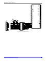
The 3U MACRO Station can be configured in either of two fundamental assemblies – “UMAC MACRO” and
“MACRO Stack”:
•
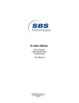
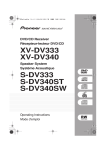
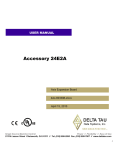
UMAC MACRO – In this configuration (once called
"Pack") the 3U-format boards are put together to
communicate through a backplane bus called the UBUS.
All boards are installed in a Euro-card rack. In this
configuration, all 3U-format boards or modules can be
installed or withdrawn from the pack individually,
providing ease of installation, debugging, and repair.
The photo at the upper right shows a UMAC rack with power
supply and I/O boards that are connected through a backplane.
This system allows for an easier integration of the 3U
MACRO-CPU for larger (up to 8 axes) applications.
•
UMAC MACRO Station
Configuration
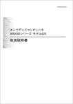
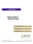
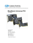
MACRO Stack – In the Stack configuration the 3U-format
boards are put together as a stack of piggyback boards,
(right, below). This configuration is ideal for compact,
cost-sensitive embedded applications.
4 Axis Stack Configuration
Note:
The Stack boards and related breakout boards can be installed in a Euro-card rack,
creating a hybrid “stack/pack” configuration. This requires a special backplane
configuration that makes removing stack boards difficult.
This hybrid configuration is now recommended for existing “legacy” systems only.
3U Product Configurations (General Description)
2
Introduction
MACRO-CPU Hardware Reference
Assemblies of 3U-format boards can be made with either of two CPU processor boards – a 3U MACRO-CPU
board, or a 3U Turbo PMAC2 CPU board. Most other 3U-format boards, labeled “Accessory” boards, can be
used with either CPU board.
•
When the 3U MACRO-CPU board is used, the resulting assemblies are called “UMAC MACRO” or "3U
MACRO Stack."
•
When the 3U Turbo PMAC2 CPU board is used, the resulting assemblies are called “UMAC Turbo” or
"Turbo Stack."
Refer to the "UMAC & 3U Stack Products Selection Guide" for more detailed descriptions of how the rack and
stack products are integrated.
UMAC and 3U-Stack Products
UMAC Products
Stack Products
UMAC Turbo
UMAC MACRO
Turbo Stack
MACRO Stack
The UMAC Turbo is composed of
a 3U-format Turbo PMAC2 CPU
board and a set of accessory boards
in 3U-format, all plugged in a
common UBUS backplane and
installed inside a 3U format rack. A
PC/104 computer and several
optional
communication
accessories (including all of the
major FieldBuses, MACRO and
Ethernet) can be installed inside the
UMAC
system
providing
convenient flexibility and virtually
unlimited expandability.
The UMAC MACRO is composed
of a MACRO Interface/CPU board
and a set of accessory boards in 3Uformat, all plugged in a common
UBUS backplane and installed
inside a 3U format rack. The UMAC
MACRO must receive commands
from
an
external
MACRO
compatible device like a PMAC2
Ultralite or a UMAC Turbo system.
The UMAC MACRO does not
support a PC/104 or communication
accessories and it is preferred for
distributed control over a MACRO
ring connection.
The Turbo stack is composed of a
3U-format Turbo PMAC2 CPU
board and a set of accessory boards
in 3U-format plugged to it in a stack
configuration. The Turbo stack
configuration is less expensive than
the UMAC Turbo system but it is
limited to eight axes of motion
control versus 32 axes on a UMAC
Turbo system. The Turbo Stack is
selected over a UMAC Turbo
system because is more compact,
allowing its installation inside
already existing cabinets with some
space limitations.
The MACRO stack is composed of
a MACRO Interface/CPU board
and a set of accessory boards in
3U-format plugged to it in a stack
configuration.
The
UMAC
MACRO must receive commands
from an external MACRO
compatible device like a PMAC2
Ultralite or a UMAC Turbo
system. The MACRO Stack is
selected over a UMAC MACRO
syst em because it is more compact,
allowing its installation inside
already existing cabinets with some
space limitations.
Introduction
3
MACRO-CPU Hardware Reference
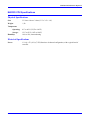
MACRO CPU Specifications
Physical Specifications
Size:
33.5cm x 9.9cm x 3.8cm (13.2" x 3.9" x 1.4")
Weight:
½ lb.
Temperature
Operating:
0°C to 60°C (32°)F to 140°F)
Storage:
12°C to 82°C (10°F to 180°F)
Humidity:
10% to 95%, noncondensing
Electrical Specifications
Power:
4
1.5A @ +5V (±5%) (7.5W) Pertains to 8-channel configuration, with a typical load of
encoders.
Introduction
MACRO-CPU Hardware Reference
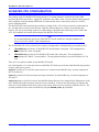
3U MACRO-CPU CONFIGURATION
The purchase of the 3U MACRO CPU board provides a 3U-format (100mm x 160mm) board with a DSP
processor, MACRO ring circuitry, “piggyback” connectors onto which “stack” accessory boards can be mounted,
and a backplane connector through which other 3U-format boards can be connected by means of a “UBUS”
passive-backplane board.
The MACRO CPU board went through an extensive redesign in the –105 revision, because key components on
the –104 and older revisions became obsolete. Both the older and the newer versions are described in this
manual. The only system change required is a slight change in the DIP-switch addressing of ACC-24E2x and
ACC-51E backplane axis boards when using the new MACRO CPU boards.
Note
It is recommended that only the new MACRO CPU boards, which have stronger backplane bus
drivers, be used in “UMAC” pack configurations.)
The 3U MACRO-CPU can be purchased in two physical configurations, distinguished by part number prefix:
•
300-602804-10x provides the 3U MACRO-CPU board without a front plate. This configuration is
recommended for “stack” assemblies.
•
3R0-602804-10x provides the 3U MACRO-CPU board with a front plate. This configuration is
recommended for “UMAC” rack assemblies. The top and bottom plates are provided with the ACC-Px
rack.
There are a few options available for the MACRO CPU board.
One of the Options A or C must be present on a MACRO CPU board to provide the actual MACRO ring interface
circuitry; both may be present:
Option A provides an SC-style fiber-optic transceiver to connect into the MACRO ring. Its main component is
the U73 transceiver.
Option C provides RJ-45 electrical input and output connectors for the MACRO ring. Its main components are
J14 and J17.
Option 10 permits a specified revision of the MACRO Station firmware to be installed in the flash memory in the
card. Without this option, the latest released revision is installed. A label on the flash memory IC indicates the
firmware revision installed at the factory (but not necessarily which revision is presently installed in the IC). The
presently installed revision can be ascertained by using the MSVER{node #} command.
3U MACRO-CPU Configuration
5
MACRO-CPU Hardware Reference
6
3U MACRO-CPU Configuration
MACRO-CPU Hardware Reference
3U MACRO CPU BOARD HARDWARE SETUP
The hardware setup of the 3U MACRO CPU Board consists of the setting of 2 rotary switches, the setting of
several E-point jumpers on each board, followed by power supply and signal connections.
Note
E-Point Jumper numbers are shown in white ink on the legend of each board. Pin numbers for
each number can be determined either from the legend on the component side on the board, or by
looking at the solder side of the board, where pin 1 has a square solder pad.
3U MACRO CPU Board Jumper & Switch Setup
The MACRO Station has two 16-way rotary switches on the MACRO CPU board that establish the station’s basic
configuration on the MACRO ring.
SW1 Rotary Switch Setting: SW1 establishes how many servo nodes, and which servo nodes, will be used on
the MACRO station. It also establishes the mapping of MACRO node numbers to MACRO Station channel
numbers. This mapping information will be important in establishing the software setup.
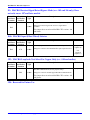
The following table shows possible MACRO Station axis configurations and the appropriate settings of SW1:
# of
Servo
Chan’s
&
Nodes
Used
Which
MACR
O Servo
Nodes
Used
Stack Axis
Boards Used
Backplane (UMAC) Axis
Boards Used
SW1 Setting
2
2
2
2
2
2
2
2
4
0, 1
4, 5
8, 9
12, 13
0, 1
4, 5
8, 9
12, 13
0, 1, 4, 5
1x ACC-1E
1x ACC-1E
1x ACC-1E
1x ACC-1E
1x ACC-2E*
1x ACC-2E*
1x ACC-2E*
1x ACC-2E*
1x ACC-2E
8
9
10 ($A)
11 ($B)
2
3
4
5
0
4
8, 9, 12,
13
0, 1, 4, 5,
8, 9
1x ACC-2E
----1x ACC-24E2x or 51E
1x ACC-24E2x or 51E
1x ACC-24E2x or 51E
1x ACC-24E2x or 51E
1x ACC-24E2x w/ Opt 1x or 1x
ACC-51E w/ Opt 1
1x ACC-24E2x w/ Opt 1x or 1x
ACC-51E w/ Opt 1
1x ACC-24E2x w/ Opt 1x or 1x
ACC-51E w/ Opt 1;
plus 1x ACC-24E2x or 51E
1x ACC-24E2x w/ Opt 1x or 1x
ACC-51E w/ Opt 1;
plus 1x ACC-24E2x or 51E
2x ACC-24E2x w/ Opt 1x /
ACC-51E w/ Opt 1
6
1x ACC-1E,
1x ACC-2E
6
0, 1, 4, 5,
8, 9
2x ACC-2E*
8
0, 1, 4, 5,
8, 9, 12,
13
2x ACC-2E
1
12 ($C)
6
7
More detailed information on the SW1 settings is presented in the Jumper/Switch description in the back of this
manual.
3U MACRO CPU Board Hardware Setup
7
MACRO-CPU Hardware Reference
SW2 Rotary Switch Setting: SW2 establishes the number of the master IC to which the MACRO station will
respond. The values of 0 to 15 correspond to Master numbers 0 to 15, respectively. For a non-Turbo PMAC2
master, this value must match the master number value in the first hexadecimal digit of PMAC2’s I996. For a
Turbo PMAC2, this value must match the master number value in the first hexadecimal digit of the Turbo
PMAC2’s I6840, I6890, I6940, or I6990, for MACRO ICs 0, 1, 2, or 3, respectively, on the Turbo PMAC2. The
default switch setting is 0, so the station will respond to Master 0.
Watchdog Timer Enable Jumper: For normal operation of the Compact MACRO Station, jumper E1 should be
OFF to enable the watchdog timer (an important safety feature).
Operational Mode Jumper: Jumper E2 should connect pins 2 and 3 to tell the CPU it is in normal operational
mode, not in “bootstrap” mode. It should only connect pins 1 and 2 if you desire to load new firmware into the
flash IC through the serial port.
Baud Rate Jumper: Jumper E3 must be ON if you are connecting an ACC-8D Option 9 Yaskawa absolute
encoder converter to the J7 serial port (most users will connect it to the JTHW port instead). This sets the baud
rate to 9600. If E3 is OFF, the baud rate is 38400.
Power Supply Check Jumper: Remove jumper E4 if you are not bringing a +/-12V to +/-15V supply into the
Compact MACRO Station itself (5V only). If you are bringing these analog circuit supplies into the Compact
MACRO Station, it is best to have jumper E4 on, so that the servo outputs are disabled if either of the analog
supplies is lost.
MACRO Input Select Jumper: Because the MACRO CPU board can potentially accept MACRO ring input
from either the RJ-45 electrical input or the fiber input, you must select which input is used (even if only one of
the ring interface options is present). Jumper E40 must be ON to use the fiber input; it must be OFF to use the
electrical input. (If both interface options A and C are present, either ring output may be used, regardless of the
setting of E40.)
MACRO Signal-Loss Detect Jumper: Jumper E5 (board revisions –105 and newer only) should connect pins 1
and 2 so that the MACRO receiver’s (fiber or electrical) loss-of-signal detect is reported automatically as a byte
“violation” error. Older revisions (-104 and before) of the board could not use the receiver’s signal-loss detect as
a “violation” error (relying on higher-level detection schemes), and connecting pins 2 and 3 makes operation of
the new revision completely compatible with the old. This is not recommended.
MACRO CPU Board Connections
The connection of Compact MACRO Station to other stations on the MACRO ring is achieved by connecting the
output connector of the Compact MACRO Station to the input connector of the next station, and by connecting
the output connector of the previous station to the input connector of the Compact MACRO Station. There must
be a completely connected ring, with all stations powered up, for any communications to occur on the ring.
Optical Fiber Ring Connection: The U73 integrated fiber optic transceiver is used for both the optical fiber
input and the optical fiber output connections to the MACRO ring. With the component side of the board up, and
the opening facing you, the input socket is on the right, and the output socket is on the left (these are marked on
the component).
RJ45 Electrical Ring Connection: The J14 connector is used for the input from the previous station on the
MACRO ring if electrical connection is used, and the J17 connector is used for the output to the next station on
the MACRO ring.
Multiplexer Port: The J6 26-pin header is used to connect to multiplexer port accessories such as the ACC-8D
Opt 7 resolver-to-digital converter board and the ACC-8D Opt. 9 Yaskawa absolute encoder interface board. This
port can be used alternately to provide 8 inputs and 8 outputs (non-multiplexed) at TTL levels.
Backplane “UBUS” Expansion Port: The P2 96-pin DIN header is used to connect to expansion port
accessories such as the ACC-9E, 10E, 11E, 12E, and 14E I/O boards, or the ACC-24E2x axis boards, through an
8
3U MACRO CPU Board Hardware Setup
MACRO-CPU Hardware Reference
ACC-Ux “UBUS” backplane board. It can also be used to bring in 5V power, and optionally +/-15V power, from
a backplane or breakout board, to the entire MACRO Station.
Note
When interfacing to accessory boards across the UBUS backplane, it is strongly recommended to
use a new revision (-105 or higher) of the MACRO CPU board, and an ACC-Ux backplane board
(not an older ACC-Jx backplane board). The newer revision MACRO CPU boards have stronger
bus driver ICs, but they do not work well with the termination of the ACC-Jx backplane boards.
Power Terminal Block: The TB1 4-point terminal block can be used to bring in 5V power, and optionally
+/-15V power, to the entire MACRO Station. In a UMAC (pack) configuration, the power is more likely to be
brought in through the backplane.
3U MACRO CPU Board Hardware Setup
9
MACRO-CPU Hardware Reference
10
3U MACRO CPU Board Hardware Setup
MACRO-CPU Hardware Reference
3U MACRO-CPU JUMPER AND SWITCH CONFIGURATIONS
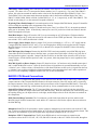
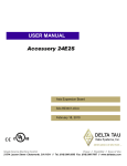
3U MACRO-CPU Card Layout
The "Location" columns of the following tables refer to the mapped locations shown in the drawings below:
A B C D E F
1
2
3
4
REV-105 and Later Revisions
REV-104 and Earlier Revisions
Note:
Pin 1 of an E-point is masked by an "X" in white ink on the composite side, and by a square
solder pad on the solder side.
3U MACRO-CPU Jumper and Switch Configurations
11
MACRO-CPU Hardware Reference
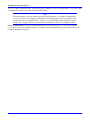
E1: Watchdog Timer Disable
Rev -105
and Later
Location
Rev -104
and Earlier
Location
Jumper
Type
Description
Remove jumper to enable Watchdog Timer.
B-1
F-1
2-PIN
Default
not jumpered
Jump pins 1 and 2 to disable Watchdog Timer (for test
purposes only)
E2: CPU Mode Operation
Rev -105
and Later
Location
D-2
Rev -104
and Earlier
Location
D-1
Jumper
Type
3-PIN
Description
Jump pins 1 and 2 for firmware download through serial
port.
Default
Pin 2-3
Jump pins 2 and 3 for normal operation.
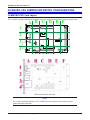
E3: Serial Port Baud Rate
Rev -105
and Later
Location
E-3
Rev -104
and Earlier
Location
E-2
Jumper
Type
2-PIN
Description
Jump pins 1 and 2 for 9600-baud serial port operation.
(Required for Yaskawa interface).
Default
not jumpered
Remove jumper for 38400-baud serial port operation.
E4: Power Supply-Loss Control (±15Vdc Supply Monitor)
Rev -105
and Later
Location
Rev -104
and Earlier
Location
Jumper
Type
Description
Jump pins 1 and 2 to disable servo outputs on loss of +5V,
+15V, or –15V power supply.
E-3
12
E-2
2-PIN
Default
not jumpered
Remove this jumper to monitor +5Vdc power supply only.
±15V supply monitoring is not usually required for
applications without DACs or A-D converters.
3U MACRO-CPU Jumper and Switch Configurations
MACRO-CPU Hardware Reference
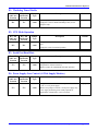
E5: MACRO Received Signal Detect/Bypass Mode (rev -105 and 106 only). Does
not exist on rev 107 and later models.
Rev -105
and Later
Location
Rev -104
and Earlier
Location
B-3
Jumper
Type
3-PIN
Description
Default
Jump pins 1 and 2 to access the receiver’s signal detect operation.
Pin 1-2
Jump pins 2 and 3 to bypass the receiver’s signal detect
operation.
This jumper does not exist on MACRO-CPU versions -104
and earlier.
E40: MACRO Input (Fiber/Wired) Selector
Rev -105
and Later
Location
B-3
Rev -104
and Earlier
Location
C-3
Jumper
Type
2-PIN
Description
Default
Remove jumper to select MACRO wired (RJ45) input from J14.
Jumpered
(Option A)
Jump pins 1 and 2 to select MACRO fiber optic input from U73.
Not
jumpered
(Option C)
JP3: MACRO Loop back Test Select For Copper Only (rev -104 and earlier)
Rev -105
and Later
Location
Rev -104
and Earlier
Location
Jumper
Type
Description
Remove jumper to select loop back in the copper interface of
MACRO communications (for test purposes only).
B-1
2-PIN
Default
jumpered
Jump pins 1 and 2 for normal copper MACRO communications.
This jumper does not exist on MACRO-CPU versions -105
and greater.
JP4: Reserved for Future Use
3U MACRO-CPU Jumper and Switch Configurations
13
MACRO-CPU Hardware Reference
JP5-JP6: MACRO Copper EQ Select (rev -104 and earlier)
Rev -105
and Later
Location
Rev -104
and Earlier
Location
B-1
Jumper
Type
2-PIN
Description
Default
These jumpers are used to select different modes of
equalization when copper-based communications are used.
not jumpered
When not jumpered, adaptive equalization is used. JP5 and
JP6 are used for manufacturer's testing only.
These jumpers do not exist on MACRO-CPU versions -105
and greater.
14
3U MACRO-CPU Jumper and Switch Configurations
MACRO-CPU Hardware Reference
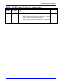
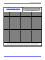
Switch Configurations
SW1: MACRO Slave Node Configure
MACRO
Servo
Nodes
Specified
Station
Channel
Nos.
Station
Channel
Starting
Addresses
1st Axis
Board
Servo
IC
2nd Axis
Board
Servo
IC
4
0, 1, 4, 5
1, 2, 3, 4
4-axis
None
4
8, 9, 12,
13
0, 1
4, 5
8, 9
12, 13
0, 1, 4, 5,
8, 9
1, 2, 3, 4
$C000, $C008,
$C010, $C018*
$C000, $C008,
$C010, $C018*
$C000, $C008*
$C010, $C018*
$C000, $C008*
$C010, $C018*
$C000, $C008,
$C010, $C018,
$C020, $C028*
$C000, $C008,
$C010, $C018,
$C020, $C028,
$C030, $C038*
$C090, $C098
$C090, $C098
$C090, $C098
$C090, $C098
$C000, $C008.
$C010, $C018,*
$C090, $C098
None
PMAC2's I996
Value **
(Turbo
PMAC2’S
I6840, etc.
$F8033
4-axis
None
$FB300
$3300
4-axis
4-axis
4-axis
4-axis
4-axis
None
None
None
None
4-axis
$F8003
$F8030
$F8300
$FB000
$F8333
$0003
$0030
$0300
$3000
$0333
4-axis
4-axis
$FB333
$3333
2-axis
2-axis
2-axis
2-axis
4-axis
None
None
None
None
2-axis
$F8003
$F8030
$F8300
$FB000
$FB333
$0003
$0030
$0300
$3000
$0333
None
None
$F8000
$0000
-
-
$F8800
SW1
Setting
# of Servo
Channels
& Nodes
Used
0
(default)
1
2
3
4
5
6
2
2
2
2
6
7
8
0, 1, 4, 5,
8, 9, 12,
13
1, 2, 3, 4,
5, 6, 7, 8
8
9
10
11
12
2
2
2
2
6
0, 1
4, 5
8, 9
12. 13
0, 1, 4, 5,
8, 9
9, 10
9, 10
9, 10
9, 10
1, 2, 3, 4,
9, 10
13
0
(I/O only)
(Reserved
0
None
None
For
Future
-
14
15
***
*
11
1, 2
3, 4
1, 2
3, 4
1, 2, 3, 4,
5, 6
PMAC2's I1000,
I1002 Value
(Turbo
PMAC2’s I70,
I71, etc.)
$0033
Use)
-
-
These addresses are for stack axis boards. Add $40 to these addresses for backplane axis boards.
** Other bits of this I-variable may also be set to enable I/O nodes or other slave stations it is commanding
*** A setting of 15 forces the station to use its factory default I-variables on power-up/reset.
SW2: MACRO Master Number Select
0: Commanded from Master IC # 0
1: Commanded from Master IC # 1
…
F: Commanded from Master IC # F (15)
3U MACRO-CPU Jumper and Switch Configurations
15
MACRO-CPU Hardware Reference
Connector Summary
J1: ☼
JEXP_A: for interboard connection
J2:
☼
JEXP_B: for interboard connection
J3:
☼
JEXP_C: for interboard connection
J4: ☼
JISP: Factory configuration header
J5:
☼
☼
JTAG/OnCE: Factory troubleshoot header
J6:
JTHW: Multiplexer Port Connector
J7:
JRS232: Serial Port Connector
J14, J17:
RJ45: MACRO Copper I/O (OPT C)
P1:
JEXP: Backplane Expansion Port Connector
TB1:
JPWR: 4-Pin Terminal Block
U73:
MACRO Fiber Optic Connector (OPT A)
These connectors are not typically designated as end-user interfaces. The pinouts are not included in this hardware
reference manual. Consult the factory if pinout information is needed.
16
3U MACRO-CPU Jumper and Switch Configurations
MACRO-CPU Hardware Reference
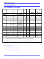
MACRO STATION CHARACTER DISPLAY
The Compact MACRO Station has a single hexadecimal character display on the CPU/Interface Board that
provides useful information as to the status of the station. The display can show the following values:
Value
(Blank)
0-8
9
A
B
C
D
E
F
MACRO Station Character Display
Meaning
Ring not active
Operation OK; value is # of motors enabled
(reserved for future use)
Amplifier fault
Ring break fault
CPU failure fault
Ring data error
Loss-of-encoder fault
Other failure
17
MACRO-CPU Hardware Reference
HARDWARE RE-INITIALIZATION
MACRO hardware reinitialization to factory defaults is enabled when the SW1 setting is set to 15 or F
(hexidecimal) and the power is cycled at the MACRO Station. The only time the user would want to use a
hardware reinitialization to factory defaults with the MACRO Station would be if the MACRO Station always
powers up with a watchdog (typically if the ring clock at the Ultralite is different than the ring clock at the
MACRO Station). Node 11 will be the only MACRO Station node enabled. Therefore the user will have to enable
node 11 of the MACRO IC at the Ultralite to communicate to the MACRO Station.
Ultralite Example: Servo nodes 0,1,4,5 enabled at Ultralite (I996=$0F8033)
(A) The user would have to enable node 11, I996=$0F8833
(B) Then user can reistablish communications with MS11,(MIvar) commands
(C) Issue MS$$$***11 to ensure re-initialization
(D) Issue MSSAVE11 command to save the factory defaults to the Station
Turbo Ultralite Example: Servo nodes 0,1,4,5 enabled at Ultralite (I6841=$0F8033)
(A) The user would have to enable node 11, I996=$0F8833
(B) Then user can reistablish communications with MS11,(MIvar) commands
(C) Issue MS$$$***11 to ensure re-initialization
(D) Issue MSSAVE11 command to save the factory defaults to the Station
18
Hardware Re-initialization
MACRO-CPU Hardware Reference
Hardware Re-initialization
19
MACRO-CPU Hardware Reference
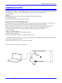
FIRMWARE UPDATES
Downloading new firmware to the MACRO Station is a simple process once the MACRO board is setup properly.
To download new firmware to the MACRO station, the user must have the following items:
5V power supply
2 jumpers
DB9 female to 10 pin header (any cable used for PMAC RS232 communications)
PC at the DOS prompt.
New firmware and necessary downloading batch files
Make sure to power down the MACRO Station
To download the software to the MACRO station, the user will first jumper the following E2 (1-2) and E1 (1-2).
Wire the 5V power to the appropriate terminal on the MACRO station or plug into 3U Rack.
Place the 10 pin header cable to the serial connection on the MACRO-station and place the other end to the
COM1 port on the PC (the batch files were written for COM1 but could be modified if necessary).
Goto the DOS prompt and create a directory called firmware and station (as an example).
C:\firmware\station
a:\copy *.* c:\firmware\station
Go back to the c drive and type the following command
c:\firmware\station\mcdwnld
The firmware will be down loaded to the MACRO station. Easy!
The PMAC Executive Software will soon have the capability of downloading the MACRO Station firmware in
the Windows Operating Environment.
(5) Place jumper E2 back to pins 2-3 and remove E1 jumper
Please call the factory if you have any questions.
20
Firmware Updates
MACRO-CPU Hardware Reference
Firmware Updates
21
MACRO-CPU Hardware Reference
3U MACRO-CPU BOARD CONNECTOR PIN-OUTS
The schematic circuits shown in this section are for interface reference only. Subtle differences may exist
between the circuits shown here and the actual hardware used.
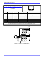
J6: (JTHW) Multiplexer Port Connector
(26-pin Header at Location D-3)
Pin #
Symbol
Function
1
2
3
4
5
6
7
8
9
10
11
12
13
14
15
16
17
18
19
20
21
22
23
24
25
26
GND
GND
DAT0
SEL0
DAT1
SEL1
DAT2
SEL2
DAT3
SEL3
DAT4
SEL4
DAT5
SEL5
DAT6
SEL6
DAT7
SEL7
N.C.
GND
BRLD/
GND
IPLD/
GND
+5V
INIT/
Common
Common
In/Out
In/Out
In/Out
In/Out
In/Out
In/Out
In/Out
In/Out
In/Out
In/Out
In/Out
In/Out
In/Out
In/Out
In/Out
In/Out
N.C
Common
Output
Common
Output
Common
Output
Input
22
Front View
Description
PMAC Common
PMAC Common
Data Byte Bit 0
Select Byte Bit 0
Data Byte Bit 1
Select Byte Bit 1
Data Byte Bit 2
Select Byte Bit 2
Data Byte Bit 3
Select Byte Bit 3
Data Byte Bit 4
Select Byte Bit 4
Data Byte Bit 5
Select Byte Bit 5
Data Byte Bit 6
Select Byte Bit 6
Data Byte Bit 7
Select Byte Bit 7
No Connection
PMAC Common
Buffer Request
PMAC Common
In Position
PMAC Common
+5VDC Supply
PMAC RESET
Notes
Must be IN for MUX
Must be OUT for MUX
Must be IN for MUX
Must be OUT for MUX
Must be IN for MUX
Must be OUT for MUX
Must be IN for MUX
Must be OUT for MUX
Must be IN for MUX
Must be OUT for MUX
Must be IN for MUX
Must be OUT for MUX
Must be IN for MUX
Must be OUT for MUX
Must be IN for MUX
Must be OUT for MUX
Low is “BUFFER REQ.”
Low is “IN POSITION”
Power Supply OUT
Low is “RESET”
3U MACRO-CPU Board Connector Pin-outs
MACRO-CPU Hardware Reference
1
2
3
4
5
6
7
8
9
10
11
12
13
14
15
16
17
18
19
20
21
22
23
24
10
1
1
J6
10
+5V
RP7
3.3KSIP10C
RP6
3.3KSIP10C
(JTHW)
1
2
3
4
5
6
7
8
9
10
11
12
13
14
15
16
17
18
19
20
21
22
23
24
25
26
U98
2
3
4
5
6
7
8
9
2
3
4
5
6
7
8
9
J6
48
47
46
45
44
43
42
41
40
39
38
37
36
35
34
33
32
31
30
29
28
27
26
25
DAT0
DAT1
DAT0
SEL0
DAT1
SEL1
DAT2
SEL2
DAT3
SEL3
DAT4
SEL4
DAT5
SEL5
DAT6
SEL6
DAT7
SEL7
DAT2
DAT3
DAT4
DAT5
+5V
DAT6
DAT7
SEL0
SEL1
SEL2
SEL3
SEL4
SEL5
SEL6
SEL7
INIT-
OE1
A0
A1
GND
A2
A3
VCC
A4
A5
GND
A6
A7
A8
A9
GND
A10
A11
VCC
A12
A13
GND
A14
A15
OE2
T/R1
B0
B1
GND
B2
B3
VCC
B4
B5
GND
B6
B7
B8
B9
GND
B10
B11
VCC
B12
B13
GND
B14
B15
T/R2
1
2
3
4
5
6
7
8
9
10
11
12
13
14
15
16
17
18
19
20
21
22
23
24
TI00
+5V
DISP0
DISP1
DISP2
DISP3
DISP4
DISP5
DISP6
DISP7
IO_24
IO_25
IO_26
IO_27
IO_28
IO_29
IO_30
IO_31
25
26
27
28
29
30
31
32
33
34
35
36
37
38
39
40
41
42
43
44
45
46
47
48
49
50
51
52
53
54
55
56
57
58
59
60
61
62
63
64
65
66
67
68
69
70
71
72
73
74
75
76
77
78
79
80
U12
VDD
VSS
FAULT_1 DATA_2
FAULT_2 DATA_3
EQU_1 DATA_4
EQU_2 DATA_5
AENA_1 DATA_6
AENA_2 DATA_7
A0
A1
A2
A3
A4
A5
A6
RD
WR
CS
ADC_STRB SEL_0
VSS2
ADC_CLK SEL_1
ADC_1 SEL_2
ADC_2 SEL_3
ADC_3 SEL_4
ADC_4 SEL_5
S_CLK SEL_6
S_CLKDIR SEL_7
SERVO
PHASE
DIN0
DIN1
DIN2
DIN3
DIN4
DIN5
DIN6
DIN7
DATA_STRB
VSS2
VDD2
VDD
CMD_IN
CMD_OUT
CMD_STROBE
DOUT0
DOUT1
DOUT2
DOUT3
DOUT4
DOUT5
DOUT6
DOUT7
VSS2
VLTN
STROBE_OUT
TCLK
CTRL0
CTRL1
CTRL2
VSS
VDD2
CTRL3
DISP0
DISP1
DISP2
DISP3
DISP4
VSS
DISP5
DISP6
DISP7
IO_24
IO_25
IO_26
IO_27
IO_28
IO_29
IO_30
IO_31
VDD2
VDD2
IO_00 FLAG_W1
IO_01 FLAG_V1
IO_02 FLAG_U1
IO_03 FLAG_T1
IO_04 FLAG_D1
IO_05 FLAG_C1
IO_06 FLAG_B1
IO_07 FLAG_A1
DATA_0 ENC_C1
ENC_B1
ENC_A1
VSS
PUL_1 PWM_C_B1
DIR_1 PWM_C_T1
IO_08 PWM_B_B1
IO_09 PWM_B_T1
IO_10 PWM_A_B1
IO_11 PWM_A_T1
VSS2
VDD
IO_12 PWM_A_T2
IO_13 PWM_A_B2
IO_14 PWM_B_T2
IO_15 PWM_B_B2
DIR_2 PWM_C_T2
PUL_2 PWM_C_B2
VSS2
ENC_A2
ENC_B2
DATA_1 ENC_C2
IO_16 FLAG_A2
IO_17 FLAG_B2
IO_18 FLAG_C2
IO_19 FLAG_D2
IO_20 FLAG_T2
IO_21 FLAG_U2
IO_22 FLAG_V2
IO_23 FLAG_W2
VDD
VDD2
VSS2
DB0
DB1
DB2
DB3
DB4
DB5
DB6
DB7
DB8
DB9
DB10
DB11
TEST1
TEST_CLK
VDD2
PLLVDD
CLK20MHZ
PLLVSS
LP1
LP2
PLLAGND
VSS2
RESET
TESTOUT
DB12
DB13
DB14
DB15
DB16
DB17
DB18
DB19
DB20
DB21
DB22
DB23
VSS
VDD
DSPGATE2A
(TQFP160)
160
159
158
157
156
155
154
153
152
151
150
149
148
147
146
145
144
143
142
141
140
139
138
137
136
135
134
133
132
131
130
129
128
127
126
125
124
123
122
121
120
119
118
117
116
115
114
113
112
111
110
109
108
107
106
105
104
103
102
101
100
99
98
97
96
95
94
93
92
91
90
89
88
87
86
85
84
83
82
81
TI01
+5V
GND
HEADER 26 GND
74FCT16245
(TSSOP)
GND
Circuitry For J6- JTHW Interface
3U MACRO-CPU Board Connector Pin-outs
23
MACRO-CPU Hardware Reference
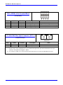
J7: (JRS232) Serial Port Connector
(10-pin Header at Location C-1)
Pin #
1
2
3
4
5
6
7
8
9
10
Symbol
Function
N.C.
DTR
TXD/
CTS
RXD/
RTS
DSR
N.C.
GND
+5V
BIDIRECT
OUTPUT
INPUT
INPUT
OUTPUT
BIDIRECT
OUTPUT
COMMON
OUTPUT
Front View
Description
Notes
No connection
Data Terminal Ready
Send Data
Clear to Send
Receive Data
Request to Send
Data Set Ready
No Connection
PMAC Common
+5VDC Supply
Just tied to “DSR”
Transmit data to host
Host Ready bit
Receive data from host
PMAC Ready bit
Just tied to “DTR”
Power supply out
+5V
C18
.1UF
C16
J7
.1UF
1
2
3
4
5
6
7
8
9
10
16
U5
4
5
14
13
7
8
V-
+V
C2+
C1+
C2-
C1-
TXD
TXD
RXD
RXD
RTS
RTS
CTS
CTS
2
1
C14
.1UF
C15
3
.1UF
11
TXD
12
RXD
10
9
CTS-
VSS
HEADER 10
TXDCTS
RXDRTS
6
+5V
15
N.C.
DTR
TXDCTS
RXDRTS
DSR
N.C.
GND
+5V
.1UF
VCC
J7
(JRS232)
C17
MAX202ECSE
(SOL16)
GND
Circuitry for J7- JRS232 Interface
24
3U MACRO-CPU Board Connector Pin-outs
MACRO-CPU Hardware Reference
J14, J17: MACRO COPPER I/O (OPT C)
(8 pin RJ45)
Front View
Pin #
Symbol
Function
Description
Notes
1
DATA+
Data +
Differential MACRO Signal.
2
DATA-
Data -
Differential MACRO Signal
3
4
5
6
7
8
unused
unused
unused
unused
unused
unused
J17: DATA+ input.
J14: DATA+ output.
J17: DATA- input.
J14: DATA- output.
See schematic below.
See schematic below.
See schematic below.
See schematic below.
See schematic below.
See schematic below.
Unused terminated pin
Unused terminated pin
Unused terminated pin
Unused terminated pin
Unused terminated pin
Unused terminated pin
The cable used for MACRO wired connections is CAT5 verified straight-through 8 conductor.
J14
J14
1
2
3
4
5
6
7
8
CON8
50
50
50
50
50
50
50
J17
50
50
WIRED OUTPUT
rj45
tx+
tx-
U94
14
15
16
3
2
1
CT
TDTD+
CMT
TXTX+
CT
RDRD+
CT
RXRX+
12
11
10
J17
1
2
3
4
5
6
7
8
WIRED INPUT
rj45
rx+
rx-
CON8
5
6
7
50
50
50
50
50
50
PE-68515
M3
MTG HOLE
75
75
50
50
50
.01 mfd 2kv
Circuitry for J14 and J17- Copper MACRO I/O
3U MACRO-CPU Board Connector Pin-outs
25
MACRO-CPU Hardware Reference
P1: UBUS Interface Connector
(96 pin EURO-Connector at F-1, 2, 3, 4)
Front View on MACRO-CPU Card
Pin #
1
2
3
4
5
6
7
8
9
10
11
12
13
14
15
16
17
18
19
20
21
22
23
24
25
26
27
28
29
30
31
32
1.
2.
26
Row A
+5Vdc
GND
BD01
BD03
BD05
BD07
BD09
BD11
BD13
BD15
BD17
BD19
BD21
BD23
BS1 (GND)
BA01
BA03
BX/Y
CS3BA05 (CS7-)
CS12CS16BA13 (n.c.)
BRDBS3 (GND)
n.c.
PHASE+
PHASE- (n.c.)
GND
-15Vdc
GND
+5Vdc
Row B
+5Vdc
GND
DAT0
SEL0
DAT1
SEL1
DAT2
SEL2
DAT3
SEL3
DAT4
SEL4
DAT5
SEL5
DAT6
SEL6
DAT7
SEL7
BA06 (n.c.)
BA07 (n.c.)
BA08 (n.c.)
BA09 (n.c.)
BA10 (n.c.)
BA11 (n.c.)
MEMCS0- (n.c.)
MEMCS1- (n.c.)
n.c.
n.c.
n.c.
PWRGUD (n.c.)
GND
+5Vdc
Row C
+5Vdc
GND
BD00
BD02
BD04
BD06
BD08
BD10
BD12
BD14
BD16
BD18
BD20
BD22
BS0 (GND)
BA00
BA02
BA04 (n.c.)
CS2CS4- (CS6-)
CS10CS14BA12 (n.c.)
BWRBS2 (GND)
RESET
SERVO+
SERVO- (n.c.)
GND
+15Vdc
GND
+5Vdc
Refer to the UBUS Specification for detailed signal descriptions. This interface is NOT VME bus compatible.
Items shown in parentheses represent pin descriptions for -104 and earlier revision MACRO-CPU boards.
3U MACRO-CPU Board Connector Pin-outs
MACRO-CPU Hardware Reference
TB1: (JPWR) 4-Pin Terminal Block
(Location B-4)
Pin #
Symbol
Function
1
2
3
4
GND
+5V
+15V
-15V
Common
Input
Input
Input
Description
Reference Voltage
Positive Supply Voltage
Positive Supply Voltage
Negative Supply Voltage
Notes
Supplies all PMAC digital circuits
+12V to +15V; used for on-board analog
-12 to –15V; used for on-board analog
U73: MACRO Fiber Optic Connector (OPT A)
(2 Socket SC-Style)
Front View
Pin #
1
2
Symbol
RX
TX
Function
Fiber Input
Fiber Output
Description
Notes
MACRO Ring Receiver
MACRO Ring Transmitter
A. The fiber optic version of MACRO uses 62.5/125 multi-mode glass fiber optic cable terminated in an SC-style
connector. The optical wavelength is 1,300nm.
B. It is possible to "adapt" wire to fiber operation when using OPT A & C on the same MACRO-CPU board.
3U MACRO-CPU Board Connector Pin-outs
27
MACRO-CPU Hardware Reference
U MACRO-CPU HARDWARE MEMORY MAP
The values in this table represent the hardware locations associated with register-based transactions that occur in
the 3U MACRO-CPU.
Reference
ADDR (hex)
CS00CS02CS04CS06CS0CS1CS2CS3CS4CS4XCS10CS12CS14CS16MEMCS0MEMCS1-
$FFC0
$FFC8
$FFD0
$FFD8
$C000
$C020
$C040
$C060
$C080
$C0C0
$FFE0
$FFE8
$FFF0
$FFF8
$D000
$E000
Description
Stack I/O select #1
Stack I/O select #2
Stack I/O select #3
Stack I/O select #4
Stack axis 1-4 select
Stack axis 5-8 select
UBUS backplane axis 1-8 select
UBUS backplane axis 5-8 select
On-board DSPGATE2 select
UBUS backplane MACROgate or DSPgate2 select (CS4- on UBUS)
UBUS backplane I/O select #1
UBUS backplane I/O select #2
UBUS backplane I/O select #3
UBUS backplane I/O select #4
UBUS hardware I/O field (was DPRCS-)
UBUS hardware I/O field (was VMECS-)
The addressing field size is 16-bits in the 3U MACRO-CPU. The address table above is similar to the PMAC2
product line.
28
U MACRO-CPU Hardware Memory Map
MACRO-CPU Hardware Reference
U MACRO-CPU Hardware Memory Map
29
MACRO-CPU Hardware Reference
ACCESSORIES
Both the Turbo and the MACRO CPU boards can support either the Stack or the UMAC configuration. The
systems are configured modularly with the selection of a series of accessory boards, some appropriate for the
Stack, and some appropriate for the UMAC. These accessories are listed here. Each has its own manual for
detailed description.
The following table shows 3U products by function:
MACRO CPU Board
Options
Board must be ordered with
either Option A or Option C.
Option A, fiber-optic
connectors
Option C, RJ-45 electrical
MACRO connectors
“Stack” Piggyback
Accessory Boards
ACC-1E, 2-Axis Interface
Stack Board (UMAC
MACRO only), 3x0-60281010x
ACC-2E, 4-Axis Interface
Stack Board,
3x0-602805-10x
ACC-3E, 48/96/144 TTL I/O
Stack Board,
3x0-602811-10x
ACC-4E, Isolated 24-In/24Out Stack Board,
3x0-602872-10x
ACC-6E, 8/16-Channel 12Bit ADC Stack Board,
3x0-602810-10x
ACC-24E2, 2-Axis Digital
PWM, 3x0-603397-10x
Option 1D, Additional 2Axis Digital PWM,
3D1-603397-10x
Option 1A, Additional 2Axis Analog,
3A1-603398-10x
ACC-24E2S, 4-Axis
Stepper, 3x0-603441-10x
ACC-3E1, 48/96/144 I/O,
3x0-603359-10x
ACC-9E, 48 In,
3x0-603283-10x
ACC-10E, Isolated 48Output Board,
3x0-603299-10x
ACC-11E, Isolated 24-In/24Out Board, 3x0-603307-10x
ACC-12E, Isolated 24In/24-Hi-Power-Out Board,
3x0-603277-10x
ACC-14E, 48 I/O,
3x0-603472-10x
UMAC BackplaneMountable
Accessory Boards –
Axis
UMAC BackplaneMountable
Accessory Boards –
I/O
ACC-24E2A, 2-Axis
Analog, 3x0-603398-10x
UMAC BackplaneMountable
Accessory Boards –
Communication
ACC-55E, (UNET)
Universal Field Bus Adapter
Network Card,
3x0-603485-10x
UMAC BackplaneMountable
Accessory Boards –
Miscellaneous
ACC-28E, 16-Bit A/D,
3x0-603404-10x
ACC-36E, A/D, D/A
Converter, 3x0-603483-10x
ACC-51E, X 4096
Interpolator,
3x0-603438-10x
ACC-53E, SSI,
3x0-603360-10x
ACC-56E, Extender Card,
300-603401-10x
ACC-57E, Yaskawa or
Mitsubishi ABS, Encoder
Unit, 3x0-603484-10x
ACC-U6, UBUS 6-Slot
ACC-U8, UBUS 8-Slot
ACC-58E, R/D Converter,
16 Bit, 3x0-603482-10x
UBUS Backplane
30
ACC-U4, UBUS 4-Slot
Accessories
MACRO-CPU Hardware Reference
Boards
Amplifiers – Analog
±10VDC Input
(Brush Motors)
Amplifiers – Digital
PWM Input
(brushless)
Backplane, 300-603462
Backplane,
300-603403-10x
Backplane,
300-603463-10x
ACC-U10, UBUS 10-Slot
Backplane,
300-603464-10x
ACC-U12, UBUS 12-Slot
Backplane,
300-603465-10x
ACC-U14, UBUS 14-Slot
Backplane,
300-603466-10x
ACC-U16, UBUS 16-Slot
Backplane,
300-603471-10x
ACC-U18, UBUS 18-Slot
Backplane,
300-603491-10x
4-Axis Analog ± 10V Input
Linear Amplifier, 24VDC,
0.5/1A,
300-603489-10x
4-Axis Analog ± 10V Input
PWM Amplifier, 48VDC,
2/4A, 300-603443-10x
Backplane, Double Analog
Amplifier, 300-603470-10x
Backplane, Single Analog
Amplifier, 300-603490-10x
2-Axis Digital PWM
Amplifier, 360VDC, 4/8A,
400-603391-10x
2-Axis Digital PWM/Macro
Amplifier, 360VDC, 8/16A,
400-603392-10x
Single Axis Digital
PWM/Macro Amplifier,
360VDC, 8/16A,
401-603391-10x
Single-Axis Digital PWM
Amplifier, 360VDC, 8/16A,
401-603492-10x
Power Supply for 3U Digital
PWM Amplifiers,
400-603428-10x
Backplane, Digital PWM,
300-603435-10x
4-Axis Analog ± 10V Input
PWM Amplifier, 70VDC,
8/12A, 300-603486-10x
Power Supplies –
DC Input
ACC-F, 3U DC to DC
Converter,10A,
30F-603216-OPT
Power Supplies –
AC Input
ACC-E, 3U AC Power
Supply, 8A,
30E-603269-OPT
ACC-E1, 3U AC Power
Supply, 14A,
31E-603269-OPT
ACC-E2, AC Power Supply,
20A, 32E-603468-OPT
UMAC Chassis
Assemblies (Rack)
3U Rack, 10-1/2 Slot (42T)
542-602932-10x
3U Rack, 15-3/4 Slot (63T)
563-602932-10x
3U Rack, 21 Slot (84T)
584-602932-10x
ACC-8DE, 2-Axis 3U
Analog-Output Breakout
Board, 3x0-603215-10x
ACC-8FE, 2-Axis 3U
Digital-Output Breakout
Board, 3x0-603176-10x
ACC-13, Encoder Terminal
Block Board,
300-603365-10x
ACC13A, Flag Terminal
Block Board,
300-603366-10x
ACC-13B, Amplifier
Terminal Block Board,
300-603367-10x
ACC-15E, Isolated 12-In/12Out Opto22 Driver &
Breakout Board,
300-603488-10x
3U Rack, Variable Width per
Customer Requirements
(custom design) ,
500-602932-10x
Hybrid Stack/Pack
Accessories
(Legacy Systems
Only)
Accessories
31