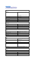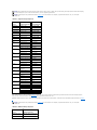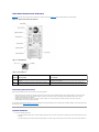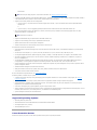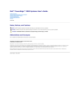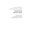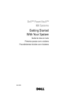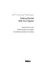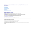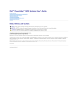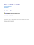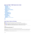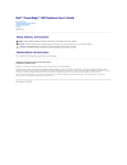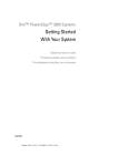
1
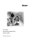
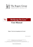
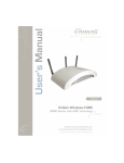
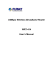
Dell™ PowerEdge™ 800 Systems User's Guide
System Overview
Using the Dell OpenManage Server Assistant
Using the System Setup Program
Technical Specifications
Using Console Redirection
Glossary
Model MVT
Notes, Notices, and Cautions
NOTE: A NOTE indicates important information that helps you make better use of your computer.
NOTICE: A NOTICE indicates either potential damage to hardware or loss of data and tells you how to avoid the problem.
CAUTION: A CAUTION indicates a potential for property damage, personal injury, or death.
Abbreviations and Acronyms
For a complete list of abbreviations and acronyms, see the Glossary.
Information in this document is subject to change without notice.
© 2004 Dell Inc. All rights reserved.
Reproduction in any manner whatsoever without the written permission of Dell Inc. is strictly forbidden.
Trademarks used in this text: Dell, the DELL logo, PowerEdge, and Dell OpenManage are trademarks of Dell Inc.; Intel, Pentium, a n d Celeron are registered trademarks of Intel
Corporation; Microsoft, Windows, and MS-DOS are registered trademarks of Microsoft Corporation; Novell and NetWare are registered trademarks of Novell, Inc.; Red Hat is a
registered trademark of Red Hat, Inc.; UNIX is a registered trademark of The Open Group in the United States and other countries.
Other trademarks and trade names may be used in this document to refer to either the entities claiming the marks and names or their products. Dell Inc. disclaims any
proprietary interest in trademarks and trade names other than its own.
Initial release: 13 Jul 2004
Back to Contents Page
Technical Specifications
Dell™ PowerEdge™ 800 Systems User's Guide
Processor
Processor type
One Intel® Celeron® processor, minimum clock
speed of 2.53 GHz
or
One Intel Pentium® 4 processor, minimum clock
speed of 2.8 GHz
Front-side bus speed
Intel Celeron
533 MHz minimum
Intel Pentium 4
800 MHz minimum
Internal cache
Intel Celeron
256 KB
Intel Pentium 4
at least 1 MB
Expansion Bus Bus type
PCI-X, PCI Express, PCI
Expansion slots
PCI-X
Two full-height, full-length 3.3-V, 64-bit, 100-MHz
PCI Express
Two 3.3-V, x1
PCI
One 5-V, 32-bit, 33-MHz
Memory Architecture
72-bit ECC unbuffered DDR2 SDRAM DIMMs, rated for
533-MHz operation, single- or dual-channel
Memory module sockets
Four 240-pin
Memory module capacities
256 MB, 512 MB, or 1 GB,
Minimum RAM
256 MB (one 256-MB module)
Maximum RAM
4 GB
Drives SATA
Up to four 1-inch, internal drives with the integrated
drive controller; up to four with the optional SATA
RAID controller card
SCSI
Up to four internal 1-inch SCSI hard drives (hot-plug
or non-hot-plug) with the optional SCSI or SCSI RAID
controller card
Diskette drive
One optional 3.5-inch, 1.44-MB
Optical drive
CD, DVD, or combination CD-RW/DVD in a peripheral
drive bay
NOTE: DVD devices are data only.
Tape backup unit
Optional IDE or SCSI in a peripheral drive bay
Connectors Externally accessible
Back
NIC
One RJ-45 (for integrated 1-Gigabit NIC)
PS/2-style keyboard
6-pin mini-DIN
PS/2-compatible mouse
6-pin mini-DIN
Parallel
25-pin
Serial
9-pin, DTE, 16550-compatible
USB
Two 4-pin, USB 2.0 compliant
Video
15-pin VGA
Front
USB
Two 4-pin, USB 2.0 compliant
Video Video type
Intel MCH; SVGA connector
Video memory
8 MB
Power AC power supply (per power supply)
Wattage
420 W
Voltage
100–240 VAC, 50/60 Hz
Heat dissipation
2275 BTU/hr maximum
Output hold up time
20 ms minimum
Maximum inrush current
Under typical line conditions and over the entire
system ambient operating range, the inrush current
may reach 55 A at 10 ms or less or 25 A at 150 ms or
less.
Battery
System battery
CR 2032 3.0-V lithium ion coin cell
Physical Height
43.9 cm (17.3 in.)
Width
19.8 cm (7.8 in.)
Depth
50.0 cm (19.7 in.)
Weight
19.1 kg (42 lb)
Environmental NOTE: For additional information about environmental measurements for specific system configurations, see
www.dell.com/environmental_datasheets.
Temperature
Operating
10° to 35°C (50° to 95°F)
Storage
–40° to 65°C (–40° to 149°F)
Relative humidity
Operating
20% to 80% (noncondensing)
Storage
5% to 95% (noncondensing)
Maximum vibration
Operating
0.25 G (half-sine wave) at a sweep of 3 to 200 MHz for 15 minutes
Storage
0.5 G at 3–200 Hz for 15 min
Maximum shock
Operating
Six consecutively executed shock pulses in the
positive and negative x, y, and z axes (one pulse on
each side of the system) of 36 G for up to 2.6 ms
Storage
Six consecutively executed shock pulses in the
positive and negative x, y, and z axes (one pulse on
each side of the system) of 71 G for up to 2 ms
Altitude
Operating
–16 to 3048 m (–50 to 10,000 ft)
Storage
–16 to 10,668 m (–50 to 35,000 ft)
Back to Contents Page
Back to Contents Page
Using Console Redirection
Dell™ PowerEdge™ 800 Systems User's Guide
Hardware Requirements
Software Requirements
Configuring the Host System
Configuring the Client System
Managing the Host System Remotely
Configuring Special Key Functions
Console redirection allows you to manage a host (local) system from a client (remote) system by redirecting keyboard input and text output through a serial
port. You cannot redirect graphic output. You can use console redirection for tasks such as configuring BIOS or RAID settings.
You can also connect the client system to a port concentrator that can access numerous host systems using a shared modem. After logging into the port
concentrator, you can select a host system to manage using console redirection.
This section describes the most basic connection possible: connecting systems using a null-modem serial cable, which directly connects the serial ports on two
systems.
Hardware Requirements
l
An available serial (COM) port on the host system
l
An available serial (COM) port on a client system
This port must not conflict with any other ports on the client system.
l
A null-modem serial cable to connect the host system to the client system
Software Requirements
l
VT 100/220 or ANSI terminal emulation with a window size of 80 x 25 characters
l
9600, 19.2 K, 57.6 K, or 115.2 K bps using serial (COM) ports
l
Ability to create keyboard command macros (recommended)
All versions of the Microsoft® Windows® operating system include Hilgraeve's HyperTerminal terminal emulation software. However, the included version does
not provide many functions required during console redirection. Either upgrade to HyperTerminal Private Edition 6.1 or later, or select new terminal emulation software.
Configuring the Host System
Configure console redirection on the host (local) system through the System Setup program (see "Console Redirection Screen" in "Using the System Setup
Program"). The Console Redirection screen allows you to enable or disable the console redirection feature, select the remote terminal type, and enable or
disable console redirection after booting.
Configuring the Client System
After configuring the host system, configure the ports and terminal settings for the client (remote) system.
NOTE: The examples in this section assume that you have upgraded to Hilgraeve's HyperTerminal Private Edition 6.1 or later. If you are using other
terminal emulation software, see the documentation for that software.
Configuring the Serial Port
1.
Click the Start button, point to Programs® Accessories® Communications, and then click HyperTerminal.
2.
Enter a name for the new connection, select an icon, and then click OK.
3.
From the Connect to drop-down menu, select an available COM port, and then click OK.
After you select an available COM port, the COM port properties window appears.
4.
Configure the port with the following settings:
l
Set Bits per second.
Console redirection supports only 9600, 19.2 K, 57.6 K, or 115.2 K bps.
l
l
Set Data bits to 8.
l
Set Parity to None.
l
Set Stop bits to 1.
l
Set Flow control to Hardware.
Click OK.
Configuring the Terminal Settings
1.
In HyperTerminal, click File, click Properties, and then click the Settings tab.
2.
Ensure that the Function, arrow, and Ctrl keys act as field is set to Terminal Keys.
3.
Ensure that the Backspace key sends field is set to Ctrl+H.
4.
Change the Emulation setting from Auto detect to ANSI or VT 100/220.
Ensure that this setting is the same as the setting you selected for the Console Redirection option on the host system.
5.
Click Terminal Setup.
A setting for the number of rows and columns appears.
6.
Change the number of rows from 24 to 25 and leave the number of columns at 80.
If you do not have these settings, you must upgrade your terminal emulation software.
7.
Click OK twice.
Managing the Host System Remotely
After you configure the host and client systems (see "Configuring the Host System" and "Configuring the Client System"), you can use console redirection to
restart a host system or to change a host system's configuration settings.
1.
Reboot the host system using the client system.
See "Configuring Special Key Functions" for instructions.
2.
When the host system begins to boot, use console redirection to:
l
Enter the System Setup program
l
Enter the SCSI setup menus
l
Update firmware and BIOS (flash the system)
l
Run utilities on the utility partition
NOTE: To run utilities on the host system's utility partition, you must have created the utility partition using Dell OpenManage™ Server Assistant version 6.3.1 or later.
Configuring Special Key Functions
Console redirection uses ANSI or VT 100/220 terminal emulation, which is limited to basic ASCII characters. Function keys, arrow keys, and control keys are not
available in the ASCII character set, and most utilities require function keys and control keys for ordinary operations. However, you can emulate a function key
or control key using a special key sequence, called an escape sequence.
An escape sequence starts with an escape character. You can enter this character in different ways, depending on the requirements of your terminal
emulation software. For example, 0x1b and <Esc> each represent the escape character. In HyperTerminal, you can create macros by selecting Key Macros
from the View menu. You can assign a macro to almost any key for almost any key combination. Create a macro to represent each function key.
Table B-1 lists the escape sequences that represent a special key or function.
NOTE: When creating macros in HyperTerminal, press <Insert> before <Esc> to signify that you are sending an escape sequence rather than escaping
out of the dialog box. If you do not have this function, you must upgrade HyperTerminal.
NOTE: Escape-sequence key combinations listed in Table B-1 are case-sensitive. For example, to generate the character <A> you must press
<Shift><a>.
Table B-1. Supported Escape Sequences Key(s)
Supported Sequence
Terminal Emulation
<Up arrow>
<Esc><[><A>
VT 100/220, ANSI
<Down arrow> <Esc><[><B>
VT 100/220, ANSI
<Right arrow>
<Esc><[><C>
VT 100/220, ANSI
<Left arrow>
<Esc><[><D>
VT 100/220, ANSI
<F1>
<Esc><O><P>
VT 100/220, ANSI
<F2>
<Esc><O><Q>
VT 100/220, ANSI
<F3>
<Esc><O><R>
VT 100/220, ANSI
<F4>
<Esc><O><S>
VT 100/220, ANSI
<F5>
<Esc><O><T>
VT 100, ANSI
<F6>
<Esc><O><U>
VT 100, ANSI
<Esc><[><1><7><~> VT 100/220
<F7>
<Esc><O><V>
VT 100, ANSI
<Esc><[><1><8><~> VT 100/220
<F8>
<Esc><O><W>
VT 100, ANSI
<Esc><[><1><9><~> VT 100/220
<F9>
<Esc><O><X>
VT 100, ANSI
<Esc><[><2><0><~> VT 100/220
<F10>
<Esc><O><Y>
VT 100, ANSI
<Esc><[><2><1><~> VT 100/220
<F11>
<Esc><O><Z>
VT 100, ANSI
<Esc><[><2><3><~> VT 100/220
<F12>
<Esc><O><A>
VT 100, ANSI
<Esc><[><2><4><~> VT 100/220
<Home>
<Esc><[><1><~>
<Esc><h>
VT 220
ANSI
<End>
<Esc><[><4><~>
VT 220
<Esc><k>
ANSI
<Esc><[><3><~>
VT 220
<Esc><–>
ANSI
<Esc><[><3><~>
VT 220
<Esc><–>
ANSI
<Esc><[><5><~>
VT 220
<Esc><Shift><?>
ANSI
<Esc><[><6><~>
VT 220
<Esc></>
ANSI
<Esc><[><Z>
VT 100
<Esc><[><0><Z>
VT 220
<Esc><[><Shift><z>
ANSI
<Delete>
<Delete>
<Page Up>
<Page Down>
<Shift><Tab>
After creating macros for the keys listed in Table B-1, press <F1> on the client system's keyboard during terminal emulation to send the escape sequence
<Esc><O><P> to the host system. The host system then interprets the sequence as <F1>.
Additional escape sequences may be required by certain utilities or functions on the host system. Create macros for the additional sequences listed in Table B2.
NOTE: Escape-sequence key combinations listed in Table B-2 are case-sensitive. For example, to generate the character <A> you must press
<Shift><a>.
Table B-2. Additional Escape Sequences
Key(s)
Supported Sequence
<Ctrl><Alt><Del>
<Esc><R><Esc><r><Esc><R>
(Reboot host system)
<Alt><x>
<Esc><X><X>
<Ctrl><H>
<Esc><Ctrl><H>
<Ctrl><I>
<Esc><Ctrl><I>
<Ctrl><J>
<Esc><Ctrl><J>
<Ctrl><M>
<Esc><Ctrl><M>
<Ctrl><2>
<Esc><Ctrl><2>
Back to Contents Page
Back to Contents Page
System Overview
Dell™ PowerEdge™ 800 Systems User's Guide
Front-Panel Features and Indicators
Back-Panel Features and Indicators
System Features
Supported Operating Systems
Power Protection Devices
Other Documents You May Need
Obtaining Technical Assistance
This section describes the major hardware and software features of your system and provides information about the indicators on the system's front and back
panels. It also provides information about other documents you may need when setting up your system and how to obtain technical assistance.
Front-Panel Features and Indicators
Figure 1-1 shows the controls, indicators, and connectors located on the system's front panel.
Figure 1-1. Front-Panel Features and Indicators
Table 1-1. Front-Panel Indicators, Buttons, and Connectors
Indicator, Button,
or Connector
Description
Blue system status The blue system status indicator lights during normal system operation.
indicator
Amber system
status indicator
The amber system status indicator flashes when the system needs attention due to a problem with power supplies, fans, system
temperature, or hot-plug hard drives.
NOTE: If the system is connected to AC power and an error has been detected, the amber system status indicator flashes regardless of
whether the system has been powered on.
Power button
Turns system power off and on.
l
l
If you turn off the system using the power button and the system is running an ACPI-compliant operating system, the system can
perform an orderly shutdown before power is turned off. If the power button is pressed for more than 4 seconds, the system
power will turn off regardless of the current operating system state.
If the system is not running an ACPI-compliant operating system, power is turned off immediately after the power button is
pressed.
The power button is enabled in the System Setup program. When disabled, the button can only turn the system power on. For more
information, see "Using the System Setup Program" and the operating system's documentation.
Power-on indicator The power-on indicator lights when the system power is on. When the indicator is off, the system is off.
To exit from a power-saving state, briefly press the power button or click or move the mouse.
Hard-drive activity
indicator
Flashes when data is being read from or written to the internal SATA hard drives that are connected to the integrated controller.
USB connectors
Connects USB 2.0-compliant devices to the system.
Back-Panel Features and Indicators
Figure 1-2 shows the controls and connectors located on the system's back panel. Figure 1-3 shows the NIC indicators on the back panel.
Figure 1-2. Back-Panel Features and Indicators
Figure 1-3. NIC Indicators
Table 1-2. NIC Indicators
Indicator Normal Operation
Error Condition
Activity
Flashing amber indicates that network data is being sent or
received.
When off at the same time that the link indicator is off, the NIC is not
connected to the network.
Link
Steady green indicates that the NIC is connected to a valid link
partner on the network.
When off at the same time that the activity indicator is off, the NIC is not
connected to the network.
Connecting External Devices
When connecting external devices to your system, follow these guidelines:
l
Most devices must be connected to a specific connector and device drivers must be installed before the device operates properly. (Device drivers are
normally included with your operating system software or with the device itself.) See the documentation that accompanied the device for specific
installation and configuration instructions.
l
Always attach external devices while your system is turned off. Next, turn on any external devices before turning on the system (unless the
documentation for the device specifies otherwise).
For information about individual connectors, see your Installation and Troubleshooting Guide. For information about enabling, disabling, and configuring I/O ports
and connectors, see "Using the System Setup Program."
System Features
l
One of the following processors:
¡
Intel® Celeron® processor with an internal operating speed of at least 2.53 GHz, internal cache of 256 KB, and a front-side bus speed of at least
533 MHz.
¡
Intel Pentium® 4 processor with an internal operating speed of at least 2.8 GHz, internal cache of at least 1 MB, and a front-side bus speed of at
least 800 MHz.
NOTE: Use the System Setup program to view processor information. See "Using the System Setup Program."
l
A minimum of 256 MB of 400-MHz or 533-MHz DDR 2 SDRAM memory, upgradable to a maximum of 4 GB by installing combinations of 256-MB, 512-MB, or
1-GB unbuffered ECC memory modules in the four memory module sockets on the system board.
l
Support for the following internal hard-drive configurations:
¡
Up to four internal, 1-inch, SATA hard drives with the integrated drive controller, or up to four SATA hard drives with the optional SATA RAID
controller card.
or
¡
l
Up to four internal, 1-inch, hot-pluggable (optional) SCSI hard drives with a SCSI controller card or SCSI RAID controller card.
One 3.5-inch peripheral drive bay for the diskette drive, and two 5.25-inch bays for any combination of the following supported drives: CD, DVD,
combination CD-RW/DVD, or tape backup unit.
NOTE: DVD devices are data only.
l
Support for hardware RAID using an optional SATA or SCSI RAID controller card.
l
Support for external storage systems using an optional RAID controller card.
l
Optional remote access card for remote systems management.
l
Chassis intrusion alarm and a bezel lock that prevents access to the hard drives.
The system board includes the following features:
l
Single integrated drive controller that supports up to four SATA hard drives and one IDE CD, DVD, or CD-RW/DVD combination drive, and an IDE tape
backup unit.
l
Five PCI slots: two PCI Express x1 (3.3 V) slots, two 64-bit, 100-MHz PCI-X (3.3 V) slots, and one 32-bit, 33-MHz PCI (5 V) slot.
l
An integrated Gigabit Ethernet NIC, capable of supporting 10-Mbps, 100-Mbps, or 1000-Mbps data rates, with support for PXE and Wake-on-LAN.
l
Four USB 2.0-compliant connectors (two on the front and two on the back) capable of supporting a diskette drive, a CD-ROM drive, a keyboard, a
mouse, or a USB flash drive.
l
An integrated SVGA-compatible video subsystem with an Intel MCH video controller. This video subsystem shares 8 MB of SDRAM system memory
(nonupgradable). True-color graphics are supported in the following resolutions: 640 x 480, 800 x 600, 1024 x 768, and 1280 x 1024. l
Systems management circuitry that monitors critical system voltages and fan speeds. The systems management circuitry works in conjunction with the
systems management software.
l
Standard baseboard management controller with serial access.
l
Back-panel connectors include mouse, keyboard, serial, video, parallel, two USB connectors, and a NIC connector.
l
Front-panel connectors include two USB connectors.
For more information about specific features, see "Technical Specifications."
The following software is included with your system:
l
A System Setup program for quickly viewing and changing system configuration information. For more information on this program, see "Using the
System Setup Program."
l
Enhanced security features, including a system password and a setup password, available through the System Setup program.
l
System diagnostics for evaluating system components and devices. For information about using the system diagnostics, see "Running the System
Diagnostics" in your Installation and Troubleshooting Guide.
l
Video drivers for displaying many popular application programs in high-resolution modes.
l
SATA or SCSI device drivers that allow the operating system to communicate with devices attached to the integrated SATA or SCSI subsystem. For more
information about these drivers, see "Installing Drives" in your Installation and Troubleshooting Guide.
l
Systems management software and documentation CDs.
Supported Operating Systems
l
Microsoft® Windows® 2000 Server
l
Microsoft Windows Server 2003 Standard Edition, and Small Business Standard Edition
l
Red Hat® Enterprise Linux (version 3)
l
Novell® NetWare® 6.5 and 5.1
Power Protection Devices
Certain devices protect your system from the effects of problems such as power surges and power failures.
l
PDU — Uses circuit breakers to ensure that the AC current load does not exceed the PDU's rating.
l
Surge protector — Prevents voltage spikes, such as those that may occur during an electrical storm, from entering the system through the electrical
outlet. They do not protect against brownouts, which occur when the voltage drops more than 20 percent below the normal AC line voltage level.
l
Line conditioner — Maintains a system's AC power source voltage at a moderately constant level and provides protection from brownouts, but does not
protect against a complete power loss.
l
UPS — Uses battery power to keep the system running when AC power is unavailable. The battery is charged by AC power while it is available so that
after AC power is lost, the battery can provide power to the system for a limited amount of time—from 5 minutes to approximately an hour. A UPS that provides only 5 minutes of battery power allows you to save your files and to shut down the system. Use surge protectors and PDUs with all universal
power supplies, and ensure that the UPS is UL-safety approved.
Other Documents You May Need
The Product Information Guide provides important safety and regulatory information. Warranty information may be included within this document or as a
separate document.
l
The Getting Started Guide describes how to set up your system for the first time.
l
The Installation and Troubleshooting Guide describes how to troubleshoot the system and install or replace system components.
l
Systems management software documentation describes the features, requirements, installation, and basic operation of the software.
l
Baseboard management controller (BMC) documentation describes the features and configuration options of the BMC.
l
Operating system documentation describes how to install (if necessary), configure, and use the operating system software.
l
Documentation for any components you purchased separately provides information to configure and install these options.
l
Updates are sometimes included with the system to describe changes to the system, software, and/or documentation.
NOTE: Always read the updates first because they often supersede information in other documents.
l
Release notes or readme files may be included to provide last-minute updates to the system or documentation or advanced technical reference material
intended for experienced users or technicians.
Obtaining Technical Assistance
If you do not understand a procedure in this guide or if the system does not perform as expected, see your Installation and Troubleshooting Guide.
Dell Enterprise Training and Certification is available; see www.dell.com/training for more information. This service may not be offered in all locations.
Back to Contents Page
Back to Contents Page
Using the Dell OpenManage Server Assistant
Dell™ PowerEdge™ 800 Systems User's Guide
Starting the Server Assistant CD
Using the Server Setup Program
Updating Drivers and Utilities
Using the Utility Partition
The Dell OpenManage Server Assistant CD contains utilities, diagnostics, and drivers to help you configure your system. You begin the operating system
installation with this CD if your operating system was not preinstalled on your system. A bootable utility partition on the system's hard drive contains some of
the same functionality as the Server Assistant CD.
Starting the Server Assistant CD
To configure your system and install your operating system, insert the Server Assistant CD, and turn on or reboot the system. The Dell OpenManage Server
Assistant main screen appears.
The Server Assistant CD uses a standard Web browser interface. You can navigate the CD by using the mouse to click various icons and text links.
Click the Exit icon to exit Server Assistant. If you exit Server Assistant while in the Server Setup program, the system reboots to the standard operating
system boot partition.
If the CD does not boot, verify that the CD drive is specified first in the Boot Sequence option in the System Setup program (see "Using the System Setup
Program").
Using the Server Setup Program
If the operating system is not preinstalled or if you install an operating system at a later date, use the Server Setup program on the Server Assistant CD to
configure your system and install your operating system.
NOTE: Use the Server Assistant CD only if your operating system is not preinstalled on your system. Locate the operating system's Installation
Instructions document and follow the instructions to complete the installation process.
The Server Setup program guides you through tasks such as the following:
l
Setting the system date and time
l
Configuring your RAID controller (if applicable)
l
Selecting and installing your operating system; specifying operating system-specific information
l
Configuring hard drives
l
Viewing the installation summary
NOTE: You must have your operating system media available to install your operating system.
To start the Server Setup program, click Server Setup on the Dell OpenManage Server Assistant main screen. Follow the instructions on the screen.
Updating Drivers and Utilities
You can update drivers and utilities on any system that has Microsoft® Internet Explorer 5.5 or later or Netscape Navigator 7.02 or later installed. When you
insert the CD into the CD drive on a system that uses a Microsoft Windows®-based operating system, the system automatically starts the browser and
displays the Dell OpenManage Server Assistant main screen.
To update drivers and utilities, perform the following steps:
1.
From the Dell OpenManage Server Assistant main screen, select the option for updating drivers and utilities.
2.
Select the system model number from the drop-down box.
3.
Select the type of drivers or utilities that you want to update.
4.
Click Continue.
5.
Select each driver or utility that you want to update.
You are prompted to either run the program or provide a location to save the files.
6.
Run the program or specify the location to save the files.
Using the Utility Partition
The utility partition is a bootable partition on the hard drive that contains system configuration and diagnostic utilities. When you start the utility partition, it
boots and provides an executable environment for the partition's utilities.
To start the utility partition, turn on or reboot the system. During POST, press <F10> after the following message appears:
<F10> = Utility Mode
NOTE: The utility partition provides only limited MS-DOS® functionality and cannot be used as a general-purpose MS-DOS partition.
The utility partition provides a text-based interface from which you can run the partition's utilities. To select a menu option, use either the arrow keys to
highlight the option and press <Enter> or type the number of the menu option. To exit the utility partition, press <Esc> from the Utility Partition main menu.
Table 2-1 provides a sample list and explanation of the options that appear on the utility partition menu. These options are available even when the Server
Assistant CD is not in the CD drive.
Table 2-1. Utility Partition Main Menu Options
Option
Description
Run system diagnostics
Runs the system hardware diagnostics
Run RAID configuration utility
Runs the RAID configuration utility if a ROMB or RAID controller card is installed
NOTE: The options displayed may vary depending on your system configuration and may not include those listed here.
Back to Contents Page
Back to Contents Page
Using the System Setup Program
Dell™ PowerEdge™ 800 Systems User's Guide
Entering the System Setup Program
System Setup Options
System and Setup Password Features
Disabling a Forgotten Password
Asset Tag Utility
Baseboard Management Controller Configuration
After you set up your system, run the System Setup program to familiarize yourself with your system configuration and optional settings. Record the
information for future reference.
You can use the System Setup program to:
l
Change the system configuration stored in NVRAM after you add, change, or remove hardware
l
Set or change user-selectable options—for example, the time or date
l
Enable or disable integrated devices
l
Correct discrepancies between the installed hardware and configuration settings
Entering the System Setup Program
1.
Turn on or restart your system.
2.
Press <F2> immediately after you see the following message:
<F2> = Setup
If your operating system begins to load before you press <F2>, allow the system to finish booting, and then restart your system and try again.
NOTE: To ensure an orderly system shutdown, see the documentation that accompanied your operating system.
Responding to Error Messages
You can enter the System Setup program by responding to certain error messages. If an error message appears while the system is booting, make a note of
the message. Before entering the System Setup program, see "System Beep Codes" and "System Messages" in your Installation and Troubleshooting Guide for
an explanation of the message and suggestions for correcting errors.
NOTE: After installing a memory upgrade, it is normal for your system to send a message the first time you start your system.
Using the System Setup Program
Table 3-1 lists the keys that you use to view or change information on the System Setup program screens and to exit the program.
Table 3-1. System Setup Program Navigation Keys Keys
Action
Up arrow or <Shift><Tab>
Moves to the previous field.
Down arrow or <Tab>
Moves to the next field.
Spacebar, <+>, <–>, left and right arrows Cycles through the settings in a field. In some fields, you can also type the appropriate value.
<Esc>
Exits the System Setup program and restarts the system if any changes were made.
<F1>
Displays the System Setup program's help file.
NOTE: For most of the options, any changes that you make are recorded but do not take effect until you restart the system.
System Setup Options
Main Screen
When you enter the System Setup program, the main System Setup program screen appears (see Figure 3-1).
Figure 3-1. Main System Setup Program Screen
Table 3-2 lists the options and descriptions for the information fields that appear on the main System Setup program screen.
NOTE: The options for the System Setup program change based on the system configuration.
NOTE: The System Setup program defaults are listed under their respective options, where applicable.
Table 3-2. System Setup Program Options Option
Description
System Time
Resets the time on the system's internal clock.
System Date
Resets the date on the system's internal calendar.
Diskette Drive A:
Displays a screen that allows you to select the type of diskette drive for your system.
System Memory
Displays the amount of system memory. This option does not have user-selectable settings.
Video Memory
Displays the amount of video memory. This option does not have user-selectable settings.
System Memory
Testing
(Enabled)
Determines if memory is being tested during POST.
OS Install Mode
(Off default)
Determines the maximum amount of memory available to the operating system. On sets the maximum memory to 256 MB. Off makes all
of the system memory available to the operating system. Some operating systems cannot install with more than 2 GB of system memory.
Enable this option (On) during operating system installation and disable (Off) after installation.
CPU Information
See "CPU Information Screen."
IDE Primary Drive
0
Enables (Auto) or disables (Off) the IDE device in Drive 0 (optical drive).
(Auto)
IDE Primary Drive
1
Enables (Auto) or disables (Off) the IDE device in Drive 1 (tape backup unit).
(Off)
SATA Port (0 – 3)
Enables (Auto) or disables (Off) the SATA hard drive in Port 0.
(Auto)
Boot Sequence
Determines the order in which the system searches for boot devices during system startup. Available options can include the diskette
drive, CD drive, hard drives, and network.
(Diskette Drive)
Hard-Disk Drive
Sequence
Determines the order in which the system searches the hard drives during system startup. The selections depend on the hard drives
installed in your system.
USB Flash Drive
Emulation Type
(Auto default)
Determines the emulation type for a USB flash drive. Hard disk allows the USB flash drive to act as a hard drive. Floppy allows the USB
flash drive to act as a removal diskette drive. Auto automatically chooses an emulation type.
Integrated
Devices
See "Integrated Devices Screen."
PCI IRQ
Assignment
Displays a screen to change the IRQ assigned to each of the integrated devices on the PCI bus, and any installed expansion cards that
require an IRQ.
Console
Redirection
See "Console Redirection Screen."
System Security
Displays a screen to configure the system password and setup password features. See "Using the System Password" and "Using the
Setup Password" for more information.
Keyboard
NumLock
(On default)
Determines whether your system starts up with the NumLock mode activated on 101- or 102-key keyboards (does not apply to 84-key
keyboards).
Report Keyboard
Errors
(Report default)
Enables or disables reporting of keyboard errors during the POST. Select Report for host systems that have keyboards attached. Select
Do Not Report to suppress all error messages relating to the keyboard or keyboard controller during POST. This setting does not affect
the operation of the keyboard itself if a keyboard is attached to the system.
Asset Tag
Displays the customer-programmable asset tag number for the system if an asset tag number has been assigned. To enter an asset tag
number of up to 10 characters into NVRAM, see "Assigning or Deleting an Asset Tag Number."
CPU Information Screen
Table 3-3 lists the options and descriptions for the information fields that appear on the CPU Information screen.
Table 3-3. CPU Information Screen
Option
Description
Bus Speed
Displays the bus speed of the processors.
Logical
Processor
(Enabled
default)
Displays when the processors support HyperThreading. Enabled permits all logical processors to be used by the operating system. Only the
first logical processor of each processor installed in the system is used by the operating system if Disabled is selected.
Processor X ID Displays the family and model number of each processor.
Core Speed
Displays the clock speed of the processor(s).
Level X Cache
Displays the amount of cache memory for the processor.
Integrated Devices Screen
Table 3-4 lists the options and descriptions for the information fields that appear on the Integrated Devices screen.
Table 3-4. Integrated Devices Screen Options Option
Description
Diskette Controller
(Auto default)
Enables or disables the system's diskette drive controller. When Auto is selected, the system turns off the controller when necessary to
accommodate a controller card installed in an expansion slot. You can also configure the drive as read-only. When using the read-only
setting, the drive cannot be used to write to a disk.
IDE Controller
(Auto default)
Enables the integrated IDE controller. When set to Auto, each channel of the integrated IDE controller is enabled if IDE devices are
attached to the channel and the external IDE controller is not detected.
SATA Controller
(ATA default)
Allows the integrated SATA controller to be set to Off, ATA, or RAID. Off disables the SATA subsystem. ATA sets the SATA subsystem to
Native IDE mode. RAID sets the SATA subsystem to RAID mode.
NOTE: RAID mode supports two drives (0 and 1). ATA mode supports all four drives.
USB Controller
(On with BIOS
support default)
Enables or disables the system's USB ports. Options are On with BIOS support, On without BIOS support, or Off. Disabling the USB
ports makes system resources available for other devices.
Embedded Gb NIC Enables or disables the system's integrated NIC. Options are Enabled without PXE, Enabled with PXE, and Disabled. PXE support
(Enabled with PXE allows the system to boot from the network. Changes take effect after the system reboots.
default)
MAC Address
Displays the MAC address for the integrated 10/100/1000 NIC. This field does not have user-selectable settings.
Serial Port 1
(COM1 default)
Serial Port 1 options are COM1, COM3, BMC Serial, BMC NIC, and Off. If an optional remote access controller (RAC) is installed in the
system, RAC is an additional option.
Serial port 1 shares three usage models. For standard usage, serial port 1 attempts to use COM1 first, and then COM3. For BMC usage,
serial port 1 uses the COM1 address and communication can be either via the Serial port or the integrated shared NIC. RAC control uses
only the COM1 address.
NOTE: Off and COM3 are not available options when Console Redirection is set to use Serial Port 1.
Parallel Port
(378h default)
Sets the address for the integrated parallel port. The options are 378h, 278h, 3BCh, and Off.
Parallel Port Mode
(PS/2 default)
Sets the operating mode for the integrated parallel port. The options are PS/2 and AT.
Speaker
(On default)
Enables or disables the system internal speaker.
System Security Screen
Table 3-5 lists the options and descriptions for the information fields that appear on the System Security screen.
Table 3-5. System Security Screen Options Option
Description
System
Password
Displays the current status of your system's password security feature and allows you to assign and verify a new system password.
NOTE: See "Using the System Password" for instructions on assigning a system password and using or changing an existing system
password.
Setup
Password
Restricts access to the System Setup program in the same way that you restrict access to your system using the system password feature.
NOTE: See "Using the Setup Password" for instructions on assigning a setup password and using or changing an existing setup password.
Password
Status
Setting the Setup Password option to Enabled prevents the system password from being changed or disabled at system start-up.
To lock the system password, assign a setup password in the Setup Password option and then change the Password Status option to
Locked. In this state, you cannot change the system password using the System Password option and cannot be disabled at system start
up by pressing <Ctrl><Enter>.
To unlock the system password, enter the setup password in the Setup Password field and then change the Password Status option to
Unlocked. In this state, you can disable the system password at system start up by pressing <Ctrl><Enter> and then change the password
using the System Password option.
Power Button Turns system's power off and on.
(Enabled
default)
l If you turn off the system using the power button and the system is running an ACPI-compliant operating system, the system can
perform an orderly shutdown before power is turned off.
l If the system is not running an ACPI-compliant operating system, power is turned off immediately after the power button is pressed.
The button is enabled in the System Setup program. When disabled, the button can only turn on system power.
AC Power
Determines how the system reacts when power is restored to the system. If system is set to Last, the system returns to the last power
Recovery
state. On turns on the system after power is restored. When set to Off, the system remains off after power is restored.
(Last default)
Console Redirection Screen
Table 3-6 lists the options and descriptions for the information fields that appear on the Console Redirection screen. For more information about using
console redirection, see "Using Console Redirection."
Table 3-6. Console Redirection Screen Options Option
Description
Console Redirection
(Off default)
Sets the console redirection feature to Serial Port 1 or Off.
Failsafe Baud Rate
(11520 default)
Displays if the failsafe baud rate is used for console redirection.
Remote Terminal Type
Select either VT 100/VT 220 or ANSI.
(VT 100/VT 220 default)
Redirection After Boot
(Enabled default)
Enables or disables console redirection after your system restarts.
Exit Screen
After you press <Esc> to exit the System Setup program, the Exit screen displays the following options:
l
Save Changes and Exit
l
Discard Changes and Exit
l
Return to Setup
System and Setup Password Features
NOTICE: The password features provide a basic level of security for the data on your system. If your data requires more security, use additional forms
of protection, such as data encryption programs.
NOTICE: Anyone can access the data stored on your system if you leave the system running and unattended without having a system password
assigned or if you leave your system unlocked so that someone can disable the password by changing a jumper setting.
Your system is shipped to you without the system password feature enabled. If system security is a concern, operate your system only with system password
protection.
To change or delete an existing password, you must know the password (see "Deleting or Changing an Existing System Password"). If you forget your
password, you cannot operate your system or change settings in the System Setup program until a trained service technician changes the password jumper
setting to disable the passwords, and erases the existing passwords. This procedure is described in the Installation and Troubleshooting Guide.
Using the System Password
After a system password is assigned, only those who know the password have full use of the system. When the System Password option is set to Enabled,
the system prompts you for the system password after the system starts.
Assigning a System Password
Before you assign a system password, enter the System Setup program and check the System Password option.
When a system password is assigned, the setting shown for the System Password option is Enabled. If the setting shown for the Password Status is
Unlocked, you can change the system password. If the Password Status option is Locked, you cannot change the system password. When the system
password feature is disabled by a jumper setting, the system password is Disabled, and you cannot change or enter a new system password.
When a system password is not assigned and the password jumper on the system board is in the enabled (default) position, the setting shown for the
System Password option is Not Enabled and the Password Status field is Unlocked. To assign a system password:
1.
Verify that the Password Status option is set to Unlocked.
2.
Highlight the System Password option and press <Enter>.
3.
Type your new system password.
You can use up to 32 characters in your password.
As you press each character key (or the spacebar for a blank space), a placeholder appears in the field.
The password assignment is not case-sensitive. However, certain key combinations are not valid. If you enter one of these combinations, the system
beeps. To erase a character when entering your password, press <Backspace> or the left-arrow key.
NOTE: To escape from the field without assigning a system password, press <Enter> to move to another field, or press <Esc> at any time prior to
completing step 5.
4.
Press <Enter>.
5.
To confirm your password, type it a second time and press <Enter>.
The setting shown for the System Password changes to Enabled. Exit the System Setup program and begin using your system.
6.
Either reboot your system now for your password protection to take effect or continue working.
NOTE: Password protection does not take effect until you reboot the system.
Using Your System Password to Secure Your System
NOTE: If you have assigned a setup password (see "Using the Setup Password"), the system accepts your setup password as an alternate system
password.
When the Password Status option is set to Unlocked, you have the option to leave the password security enabled or to disable the password security.
To leave the password security enabled:
1.
Turn on or reboot your system by pressing <Ctrl><Alt><Del>.
2.
Press <Enter>.
3.
Type your password and press <Enter>.
To disable the password security:
1.
Turn on or reboot your system by pressing <Ctrl><Alt><Del>.
2.
Press <Ctrl><Enter>.
When the Password Status option is set to Locked whenever you turn on your system or reboot your system by pressing <Ctrl><Alt><Del>, type your
password and press <Enter> at the prompt.
After you type the correct system password and press <Enter>, your system operates as usual.
If an incorrect system password is entered, the system displays a message and prompts you to re-enter your password. You have three attempts to enter the
correct password. After the third unsuccessful attempt, the system displays an error message showing the number of unsuccessful attempts and that the
system has halted and will shut down. This message can alert you to an unauthorized person attempting to use your system.
Even after you shut down and restart the system, the error message continues to be displayed until the correct password is entered.
NOTE: You can use the Password Status option in conjunction with the System Password and Setup Password options to further protect your system
from unauthorized changes.
Deleting or Changing an Existing System Password
1.
When prompted, press <Ctrl><Enter> to disable the existing system password.
If you are asked to enter your setup password, contact your network administrator.
2.
Enter the System Setup program by pressing <F2> during POST.
3.
Select the System Security screen field to verify that the Password Status option is set to Unlocked.
4.
When prompted, type the system password.
5.
Confirm that Not Enabled is displayed for the System Password option.
If Not Enabled is displayed for the System Password option, the system password has been deleted. If Enabled is displayed for the System Password
option, press the <Alt><b> key combination to restart the system, and then repeat steps 2 through 5.
Using the Setup Password
Assigning a Setup Password
You can assign (or change) a setup password only when the Setup Password option is set to Not Enabled. To assign a setup password, highlight the Setup
Password option and press the <+> or <–> key. The system prompts you to enter and verify the password. If a character is illegal for password use, the
system beeps.
NOTE: The setup password can be the same as the system password. If the two passwords are different, the setup password can be used as an
alternate system password. However, the system password cannot be used in place of the setup password.
You can use up to 32 characters in your password.
As you press each character key (or the spacebar for a blank space), a placeholder appears in the field.
The password assignment is not case-sensitive. However, certain key combinations are not valid. If you enter one of these combinations, the system beeps.
To erase a character when entering your password, press <Backspace> or the left-arrow key.
After you verify the password, the Setup Password setting changes to Enabled. The next time you enter the System Setup program, the system prompts you
for the setup password.
A change to the Setup Password option becomes effective immediately (restarting the system is not required).
Operating With a Setup Password Enabled
If Setup Password is set to Enabled, you must enter the correct setup password before you can modify most of the System Setup options. When you start
the System Setup program, the program prompts you to enter a password.
If you do not enter the correct password in three attempts, the system lets you view, but not modify, the System Setup screens—with the following exception:
If System Password is not set to Enabled and is not locked through the Password Status option, you can assign a system password (however, you cannot
disable or change an existing system password).
NOTE: You can use the Password Status option in conjunction with the Setup Password option to protect the system password from unauthorized
changes.
Deleting or Changing an Existing Setup Password
1.
2.
Enter the System Setup program and select the System Security option.
Highlight the Setup Password option, press <Enter> to access the setup password window, and press <Enter> twice to clear the existing setup
password.
The setting changes to Not Enabled.
3.
If you want to assign a new setup password, perform the steps in "Assigning a Setup Password."
Disabling a Forgotten Password
See your Installation and Troubleshooting Guide.
Asset Tag Utility
You can use the Asset Tag utility to assign a unique tracking number to your system. This number is displayed on the System Setup program main screen.
NOTE: The Asset Tag utility works only with operating systems that support MS-DOS®-based applications.
Creating the Asset Tag Utility Diskette
1.
Insert the Dell OpenManage Server Assistant CD into the CD drive of a system running a Microsoft® Windows® operating system.
2.
Insert a blank diskette into the system's diskette drive.
3.
Select the system for which you want to create an asset tag and click Continue.
4.
On the Utilities and Drivers Page, select Dell: Bootable Diskette with Asset Tag Utility.
5.
Save the utility to the hard drive and then execute the utility to create a bootable diskette.
6.
Insert the diskette into the system for which you want to assign the asset tag and reboot the system.
Assigning or Deleting an Asset Tag Number
1.
Insert the Asset Tag utility diskette that you created into the diskette drive, and reboot the system.
2.
You can either assign or delete an asset tag number.
l
To assign an asset tag number, type asset and a space followed by the new string.
An asset tag number can have up to 10 characters. Any combination of characters (excluding |, <, >) is valid; however, do not use - as the first
character. For example, at the a:\> prompt, type the following command and press <Enter>:
asset 12345abcde
l
l
To delete an asset tag number without assigning a new one, type asset /d and press <Enter>.
When prompted to verify the change to the asset tag number, type y and press <Enter>.
To view the Asset Tag utility help screen, type asset /? and press <Enter>.
Baseboard Management Controller Configuration
The Baseboard Management Controller (BMC) enables configuring, monitoring, and recovery of systems remotely. BMC provides the following features:
l
Uses the system's serial port and integrated NIC
l
Fault logging and SNMP alerting
l
Access to system event log and sensor status
l
Control of system functions including power on and off
l
Support is independent of the system's power or operating state
l
Provides text console redirection for system setup, text-based utilities, and operating system consoles
NOTE: To remotely access the BMC through the integrated NIC, you must connect the network connection to integrated NIC1. See Figure 1-3.
For additional information on using BMC, see the documentation for the BMC and systems management applications.
Entering the BMC Setup Module
1.
Turn on or restart your system.
2.
Press <Ctrl-E> when prompted after POST.
If your operating system begins to load before you press <Crtl-E>, allow the system to finish booting, and then restart your system and try again.
BMC Setup Module Options
For information about the BMC Setup Module options and how to configure the emergency management port (EMP), see the BMC User's Guide.
Back to Contents Page
Back to Contents Page
Glossary
Dell™ PowerEdge™ 800 Systems User's Guide
This section defines or identifies technical terms, abbreviations, and acronyms used in your system documents.
A — Ampere(s).
AC — Alternating current.
ACPI — Advanced Configuration and Power Interface. A standard interface for enabling the operating system to direct configuration and power
management.
ambient temperature — The temperature of the area or room where the system is located.
ANSI — American National Standards Institute. The primary organization for developing technology standards in the U.S.
application — Software designed to help you perform a specific task or series of tasks. Applications run from the operating system.
ASCII — American Standard Code for Information Interchange.
asset tag — An individual code assigned to a system, usually by an administrator, for security or tracking purposes.
backup — A copy of a program or data file. As a precaution, back up your system's hard drive on a regular basis. Before making a change to the
configuration of your system, back up important start-up files from your operating system.
backup battery — A battery that maintains system configuration, date, and time information in a special section of memory when the system is turned off.
beep code — A diagnostic message in the form of a pattern of beeps from your system's speaker. For example, one beep, followed by a second beep, and
then a burst of three beeps is beep code 1-1-3.
BIOS — Basic input/output system. Your system's BIOS contains programs stored on a flash memory chip. The BIOS controls the following:
l
l
Communications between the processor and peripheral devices
Miscellaneous functions, such as system messages
bit — The smallest unit of information interpreted by your system.
blade — A module that contains a processor, memory, and a hard drive. The modules are mounted into a chassis that includes power supplies and fans.
BMC — Baseboard management controller.
boot routine — A program that clears all memory, initializes devices, and loads the operating system when you start your system. Unless the operating
system fails to respond, you can reboot (also called warm boot) your system by pressing <Ctrl><Alt><Del>. Otherwise, you must restart the system by
pressing the reset button or by turning the system off and then back on.
bootable diskette — A diskette that is used to start your system if the system will not boot from the hard drive.
BTU — British thermal unit.
bus — An information pathway between the components of a system. Your system contains an expansion bus that allows the processor to communicate
with controllers for the peripheral devices connected to the system. Your system also contains an address bus and a data bus for communications between
the processor and RAM.
C — Celsius.
cache — A fast storage area that keeps a copy of data or instructions for quick data retrieval. When a program makes a request to a disk drive for data that
is in the cache, the disk-cache utility can retrieve the data from RAM faster than from the disk drive.
CD — Compact disc. CD drives use optical technology to read data from CDs.
cm — Centimeter(s).
cmos — Complementary metal-oxide semiconductor.
component — As they relate to DMI, components include operating systems, computer systems, expansion cards, and peripherals that are compatible with
DMI. Each component is made up of groups and attributes that are defined as relevant to that component.
COMn — The device names for the serial ports on your system.
control panel — The part of the system that contains indicators and controls, such as the power button and power indicator.
controller — A chip that controls the transfer of data between the processor and memory or between the processor and a peripheral.
conventional memory — The first 640 KB of RAM. Conventional memory is found in all systems. Unless they are specially designed, MS-DOS® programs are
limited to running in conventional memory.
coprocessor — A chip that relieves the system's processor of specific processing tasks. A math coprocessor, for example, handles numeric processing.
CPU — Central processing unit. See processor.
DC — Direct current.
DDR — Double-data rate. A technology in memory modules that potentially doubles the output.
device driver — A program that allows the operating system or some other program to interface correctly with a peripheral. Some device drivers—such as
network drivers—must be loaded from the config.sys file or as memory-resident programs (usually, from the autoexec.bat file). Others must load when you
start the program for which they were designed.
DHCP — Dynamic Host Configuration Protocol. A method of automatically assigning an IP address to a client system.
diagnostics — A comprehensive set of tests for your system.
DIMM — Dual in-line memory module. See also memory module.
DIN — Deutsche Industrie Norm.
directory — Directories help keep related files organized on a disk in a hierarchical, "inverted tree" structure. Each disk has a "root" directory. Additional
directories that branch off the root directory are called subdirectories. Subdirectories may contain additional directories branching off them.
DMA — Direct memory access. A DMA channel allows certain types of data transfer between RAM and a device to bypass the processor.
DMI — Desktop Management Interface. DMI enables the management of your system's software and hardware by collecting information about the system's
components, such as the operating system, memory, peripherals, expansion cards, and asset tag.
DNS — Domain Name System. A method of translating Internet domain names, such as www.dell.com, into IP addresses, such as 143.166.83.200.
DRAM — Dynamic random-access memory. A system's RAM is usually made up entirely of DRAM chips.
DVD — Digital versatile disc.
ECC — Error checking and correction.
EEPROM — Electronically erasable programmable read-only memory.
EMC — Electromagnetic compatibility.
EMI — Electromagnetic interference.
ERA — Embedded remote access. ERA allows you to perform remote, or "out-of-band," server management on your network server using a remote access
controller.
ESD — Electrostatic discharge.
ESM — Embedded server management.
expansion bus — Your system contains an expansion bus that allows the processor to communicate with controllers for peripherals, such as NICs.
expansion card — An add-in card, such as a NIC or SCSI adapter, that plugs into an expansion-card connector on the system board. An expansion card adds
some specialized function to the system by providing an interface between the expansion bus and a peripheral.
expansion-card connector — A connector on the system board or riser board for plugging in an expansion card.
F — Fahrenheit.
FAT — File allocation table. The file system structure used by MS-DOS to organize and keep track of file storage. The Microsoft® Windows® operating
systems can optionally use a FAT file system structure.
flash memory — A type of EEPROM chip that can be reprogrammed from a utility on diskette while still installed in a system; most EEPROM chips can only be
rewritten with special programming equipment.
format — To prepare a hard drive or diskette for storing files. An unconditional format deletes all data stored on the disk.
FSB — Front-side bus. The FSB is the data path and physical interface between the processor and the main memory (RAM).
ft — Feet.
FTP — File transfer protocol.
g — Gram(s).
G — Gravities.
Gb — Gigabit(s); 1024 megabits or 1,073,741,824 bits.
GB — Gigabyte(s); 1024 megabytes or 1,073,741,824 bytes. However, when referring to hard-drive capacity, the term is usually rounded to 1,000,000,000
bytes.
graphics mode — A video mode that can be defined as x horizontal by y vertical pixels by z colors.
group — As it relates to DMI, a group is a data structure that defines common information, or attributes, about a manageable component.
guarding — A type of data redundancy in which a set of physical drives stores data and an additional drive stores parity data. See also mirroring, striping,
and RAID.
h — Hexadecimal. A base-16 numbering system, often used in programming to identify addresses in the system's RAM and I/O memory addresses for
devices. In text, hexadecimal numbers are often followed by h.
headless system — A system or device that functions without having a keyboard, mouse, or monitor attached. Normally, headless systems are managed
over a network using an Internet browser.
host adapter — A host adapter implements communication between the system's bus and the controller for a peripheral device. (Hard-drive controller
subsystems include integrated host adapter circuitry.) To add a SCSI expansion bus to your system, you must install or connect the appropriate host
adapter.
Hz — Hertz.
I/O — Input/output. A keyboard is an input device, and a monitor is an output device. In general, I/O activity can be differentiated from computational
activity.
ID — Identification.
IDE — Integrated drive electronics. A standard interface between the system board and storage devices.
integrated mirroring — Provides simultaneous physical mirroring of two drives. Integrated mirroring functionality is provided by the system's hardware. See
also mirroring.
internal processor cache — An instruction and data cache built into the processor.
IP — Internet Protocol.
IPX — Internet package exchange.
IRQ — Interrupt request. A signal that data is about to be sent to or received by a peripheral device travels by an IRQ line to the processor. Each peripheral
connection must be assigned an IRQ number. Two devices can share the same IRQ assignment, but you cannot operate both devices simultaneously.
jumper — Small blocks on a circuit board with two or more pins emerging from them. Plastic plugs containing a wire fit down over the pins. The wire connects
the pins and creates a circuit, providing a simple and reversible method of changing the circuitry in a board.
K — Kilo-; 1000.
Kb — Kilobit(s); 1024 bits.
KB — Kilobyte(s); 1024 bytes.
Kbps — Kilobit(s) per second.
KBps — Kilobyte(s) per second.
key combination — A command requiring you to press multiple keys at the same time (for example, <Ctrl><Alt><Del>).
kg — Kilogram(s); 1000 grams.
kHz — Kilohertz.
KMM — Keyboard/monitor/mouse.
KVM — Keyboard/video/mouse. KVM refers to a switch that allows selection of the system from which the video
is displayed and for which the keyboard and mouse are used.
LAN — Local area network. A LAN is usually confined to the same building or a few nearby buildings, with all equipment linked by wiring dedicated specifically
to the LAN.
lb — Pound(s).
LCD — Liquid crystal display.
LED — Light-emitting diode. An electronic device that lights up when a current is passed through it.
Linux — A version of the UNIX® operating system that runs on a variety of hardware systems. Linux is open source software, which is freely available;
however, the full distribution of Linux along with technical support and training are available for a fee from vendors such as Red Hat Software.
local bus — On a system with local-bus expansion capability, certain peripheral devices (such as the video adapter circuitry) can be designed to run much
faster than they would with a traditional expansion bus. See also bus.
LVD — Low voltage differential.
m — Meter(s).
mA — Milliampere(s).
MAC address — Media Access Control address. Your system's unique hardware number on a network.
mAh — Milliampere-hour(s).
Mb — Megabit(s); 1,048,576 bits.
MB — Megabyte(s); 1,048,576 bytes. However, when referring to hard-drive capacity, the term is often rounded to mean 1,000,000 bytes.
Mbps — Megabits per second.
MBps — Megabytes per second.
MBR — Master boot record.
memory address — A specific location, usually expressed as a hexadecimal number, in the system's RAM.
memory module — A small circuit board containing DRAM chips that connects to the system board.
memory — An area in your system that stores basic system data. A system can contain several different forms of memory, such as integrated memory (ROM
and RAM) and add-in memory modules (DIMMs).
MHz — Megahertz.
mirroring — A type of data redundancy in which a set of physical drives stores data and one or more sets of additional drives stores duplicate copies of the
data. Mirroring functionality is provided by software. See also guarding, integrated mirroring, striping, and RAID.
mm — Millimeter(s).
ms — Millisecond(s).
MS-DOS® — Microsoft Disk Operating System.
NAS — Network Attached Storage. NAS is one of the concepts used for implementing shared storage on a network. NAS systems have their own operating
systems, integrated hardware, and software that are optimized to serve specific storage needs.
NIC — Network interface controller. A device that is installed or integrated in a system to allow connection to a network.
NMI — Nonmaskable interrupt. A device sends an NMI to signal the processor about hardware errors.
ns — Nanosecond(s).
NTFS — The NT File System option in the Windows 2000 operating system.
NVRAM — Nonvolatile random-access memory. Memory that does not lose its contents when you turn off your system. NVRAM is used for maintaining the
date, time, and system configuration information.
parity — Redundant information that is associated with a block of data.
partition — You can divide a hard drive into multiple physical sections called partitions with the fdisk command. Each partition can contain multiple logical
drives. You must format each logical drive with the format command.
PCI — Peripheral Component Interconnect. A standard for local-bus implementation.
PDU — Power distribution unit. A power source with multiple power outlets that provides electrical power to servers and storage systems in a rack.
peripheral — An internal or external device, such as a diskette drive or keyboard, connected to a system.
PGA — Pin grid array. A type of processor socket that allows you to remove the processor chip.
pixel — A single point on a video display. Pixels are arranged in rows and columns to create an image. A video resolution, such as 640 x 480, is expressed
as the number of pixels across by the number of pixels up and down.
POST — Power-on self-test. Before the operating system loads when you turn on your system, the POST tests various system components such as RAM and
hard drives.
processor — The primary computational chip inside the system that controls the interpretation and execution of arithmetic and logic functions. Software
written for one processor must usually be revised to run on another processor. CPU is a synonym for processor.
protected mode — An operating mode that allows operating systems to implement:
l
l
l
A memory address space of 16 MB to 4 GB
Multitasking
Virtual memory, a method for increasing addressable memory by using the hard drive
The Windows 2000 and UNIX 32-bit operating systems run in protected mode. MS-DOS cannot run in protected mode.
PS/2 — Personal System/2.
PXE — Preboot eXecution Environment. A way of booting a system via a LAN (without a hard drive or bootable diskette).
RAC — Remote access controller.
RAID — Redundant array of independent disks. A method of providing data redundancy. Some common implementations of RAID include RAID 0, RAID 1, RAID 5, RAID 10, and RAID 50. See also guarding, mirroring, and striping.
RAM — Random-access memory. The system's primary temporary storage area for program instructions and data. Any information stored in RAM is lost when
you turn off your system.
RAS — Remote Access Service. This service allows users running the Windows operating system to remotely access a network from their system using a
modem.
readme file — A text file, usually shipped with software or hardware, that contains information supplementing or updating the product's documentation.
read-only file — A read-only file is one that you are prohibited from editing or deleting.
ROM — Read-only memory. Your system contains some programs essential to its operation in ROM code. A ROM chip retains its contents even after you turn
off your system. Examples of code in ROM include the program that initiates your system's boot routine and the POST.
ROMB — RAID on motherboard.
rpm — Revolutions per minute.
RTC — Real-time clock.
SATA — Serial Advanced Technology Attachment. A standard interface between the system board and storage devices.
SCSI — Small computer system interface. A n I/O bus interface with faster data transmission rates than standard ports.
SDRAM — Synchronous dynamic random-access memory.
sec — Second(s).
serial port — An I/O port used most often to connect a modem to your system. You can usually identify a serial port on your system by its 9-pin connector.
service tag — A bar code label on the system used to identify it when you call Dell for technical support.
SMART — Self-Monitoring Analysis and Reporting Technology. Allows hard drives to report errors and failures to the system BIOS and then display an error
message on the screen.
SMP — Symmetric multiprocessing. Used to describe a system that has two or more processors connected via a high-bandwidth link and managed by an
operating system, where each processor has equal access to I/O devices.
SNMP — Simple Network Management Protocol. A standard interface that allows a network manager to remotely monitor and manage workstations.
striping — Disk striping writes data across three or more disks in an array, but only uses a portion of the space on each disk. The amount of space used by a
"stripe" is the same on each disk used. A virtual disk may use several stripes on the same set of disks in an array. See also guarding, mirroring, and RAID.
SVGA — Super video graphics array. VGA and SVGA are video standards for video adapters with greater resolution and color display capabilities than
previous standards.
system board — As the main circuit board, the system board usually contains most of your system's integral components, such as the processor, RAM,
controllers for peripherals, and various ROM chips.
system configuration information — Data stored in memory that tells a system what hardware is installed and how the system should be configured for
operation.
system diskette — See bootable diskette.
system memory — See RAM.
System Setup program — A BIOS-based program that allows you to configure your system's hardware and customize the system's operation by setting
features such as password protection. Because the System Setup program is stored in NVRAM, any settings remain in effect until you change them again.
system.ini file — A start-up file for the Windows operating system. When you start Windows, it consults the system.ini file to determine a variety of options
for the Windows operating environment. Among other things, the system.ini file records which video, mouse, and keyboard drivers are installed for
Windows.
TCP/IP — Transmission Control Protocol/Internet Protocol.
termination — Some devices (such as the last device at each end of a SCSI cable) must be terminated to prevent reflections and spurious signals in the
cable. When such devices are connected in a series, you may need to enable or disable the termination on these devices by changing jumper or switch
settings on the devices or by changing settings in the configuration software for the devices.
UNIX — Universal Internet Exchange. UNIX, the precursor to Linux, is an operating system written in the C programming language.
uplink port — A port on a network hub or switch used to connect to other hubs or switches without requiring a crossover cable.
UPS — Uninterruptible power supply. A battery-powered unit that automatically supplies power to your system in the event of an electrical failure.
USB — Universal Serial Bus. A USB connector provides a single connection point for multiple USB-compliant devices, such as mice and keyboards. USB devices
can be connected and disconnected while the system is running.
utility — A program used to manage system resources—memory, disk drives, or printers, for example.
UTP — Unshielded twisted pair. A type of wiring used to connect systems in a business or home to a telephone line.
V — Volt(s).
VAC — Volt(s) alternating current.
VDC — Volt(s) direct current.
VGA — Video graphics array. VGA and SVGA are video standards for video adapters with greater resolution and color display capabilities than previous
standards.
video adapter — The logical circuitry that provides (in combination with the monitor) your system's video capabilities. A video adapter may be integrated into
the system board or may be an expansion card that plugs into an expansion slot.
video driver — A program that allows graphics-mode application programs and operating systems to display at a chosen resolution with the desired number
of colors. Video drivers may need to match the video adapter installed in the system.
video memory — Most VGA and SVGA video adapters include memory chips in addition to your system's RAM. The amount of video memory installed primarily
influences the number of colors that a program can display (with the appropriate video drivers and monitor capabilities).
video resolution — Video resolution (800 x 600, for example) is expressed as the number of pixels across by the number of pixels up and down. To display a
program at a specific graphics resolution, you must install the appropriate video drivers and your monitor must support the resolution.
W — Watt(s).
WH — Watt-hour(s).
win.ini file — A start-up file for the Windows operating system. When you start Windows, it consults the win.ini file to determine a variety of options for the
Windows operating environment. The win.ini file also usually includes sections that contain optional settings for Windows application programs that are
installed on the hard drive.
Windows 2000 — An integrated and complete Microsoft Windows operating system that does not require MS-DOS and that provides advanced operating system performance, improved ease of use, enhanced workgroup functionality, and simplified file management and browsing.
Windows Powered — A Windows operating system designed for use on NAS systems. For NAS systems, the Windows Powered operating system is
dedicated to file service for network clients.
Windows Server 2003 — A set of Microsoft software technologies that enable software integration through the use of XML Web services. XML Web services
are small reusable applications written in XML that allow data to be communicated between otherwise unconnected sources.
XML — Extensible Markup Language. XML is a way to create common information formats and to share both the format and the data on the World Wide
Web, intranets, and elsewhere.
ZIF — Zero insertion force.
Back to Contents Page