1
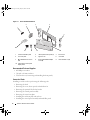
book.book Page 1 Friday, May 26, 2006 3:03 PM
Dell™ Systems
Tower-to-Rack
Conversion Guide
w w w. d e l l . c o m | s u p p o r t . d e l l . c o m
book.book Page 2 Friday, May 26, 2006 3:03 PM
book.book Page 1 Friday, May 26, 2006 3:03 PM
Dell™ Systems
Tower-to-Rack
Conversion Guide
w w w. d e l l . c o m | s u p p o r t . d e l l . c o m
book.book Page 2 Friday, May 26, 2006 3:03 PM
Notes, Notices, and Cautions
NOTE: A NOTE indicates important information that helps you make better use of your computer.
NOTICE: A NOTICE indicates either potential damage to hardware or loss of data and tells you how to avoid the
problem.
CAUTION: A CAUTION indicates a potential for property damage, personal injury, or death.
____________________
Information in this document is subject to change without notice.
© 2006 Dell Inc. All rights reserved.
Reproduction in any manner whatsoever without the written permission of Dell Inc. is strictly forbidden.
Trademarks used in this text: Dell, RapidRails, VersaRails, and the DELL logo are trademarks of Dell Inc.
Other trademarks and trade names may be used in this document to refer to either the entities claiming the marks and names or their products.
Dell Inc. disclaims any proprietary interest in trademarks and trade names other than its own.
April 2006
P/N JH985
Rev. A01
book.book Page 3 Friday, May 26, 2006 3:03 PM
Contents
CAUTION: Safety Instructions .
. . . . . . . . . . . . . . . . . . . . . . . . . .
. . . . . . . . . . . . . . . . . . . . .
5
. . . . . . . . . . . . . . . . . . . . . . . . .
6
. . . . . . . . . . . . . . . . . . . . . . . . . . . . . . .
6
SAFETY: Rack Mounting of Systems
General Installation Instructions
Before You Begin
5
Installing the Tower-to-Rack Kit .
. . . . . . . . . . . . . . . . . . . . . . . . .
Tower-to-Rack Kit Contents. . . . . . . . . . . . . .
Recommended Tools and Supplies . . . . . . . . . .
Conversion Tasks . . . . . . . . . . . . . . . . . . .
Removing the Bezel . . . . . . . . . . . . . . . . . .
Preparing the System for Conversion . . . . . . . . .
Removing the System Cover . . . . . . . . . . . . .
Removing the Stabilizer Feet . . . . . . . . . . . . .
Removing the Top Chassis Panel . . . . . . . . . . .
Removing the Bottom Chassis Panel . . . . . . . . .
Removing the Optional 1x2 Flex Bay Bracket. . . . .
Removing the Control Panel Assembly . . . . . . . .
Removing the Tower Front Plate . . . . . . . . . . .
Installing the Rack Front Plate . . . . . . . . . . . .
Installing the Control Panel Assembly . . . . . . . .
Installing the Optional 1x2 Flex Bay Bracket . . . . .
Installing the System Cover . . . . . . . . . . . . . .
Installing the Shoulder Nuts and Plastic Filler Panels
Removing the Rack Doors . . . . . . . . . . . . . .
Installing the System in a Rack . . . . . . . . . . . .
Installing the Cable-Management Arm . . . . . . . .
Routing Cables . . . . . . . . . . . . . . . . . . . .
Installing the Rack Bezel . . . . . . . . . . . . . . .
Installing the Rack Doors . . . . . . . . . . . . . . .
. . . . . . . . . . . .
. . . . . . . . . . . .
. . . . . . . . . . . .
. . . . . . . . . . . .
. . . . . . . . . . .
. . . . . . . . . . .
. . . . . . . . . . .
. . . . . . . . . . .
. . . . . . . . . . .
. . . . . . . . . . .
. . . . . . . . . . .
. . . . . . . . . . .
. . . . . . . . . . .
. . . . . . . . . . .
. . . . . . . . . . .
. . . . . . . . . . .
. . . . . . . . . . .
. . . . . . . . . . .
. . . . . . . . . . .
. . . . . . . . . . .
. . . . . . . . . . .
. . . . . . . . . . .
. . . . . . . . . . .
7
7
8
8
9
10
11
11
11
11
13
13
15
15
17
19
20
20
21
21
22
22
22
22
Contents
3
book.book Page 4 Friday, May 26, 2006 3:03 PM
4
Contents
book.book Page 5 Friday, May 26, 2006 3:03 PM
CAUTION: Safety Instructions
Use the following safety guidelines to help ensure your own personal safety and to help protect your
system and working environment from potential damage. For complete safety and regulatory
information, see the Product Information Guide that shipped with your system. Warranty information
might be included in this document or as a separate document.
SAFETY: Rack Mounting of Systems
Observe the following precautions for rack stability and safety. Also refer to the rack installation
documentation accompanying the system and the rack for specific caution statements and procedures.
Systems are considered to be components in a rack. Thus, "component" refers to any system as well as to
various peripherals or supporting hardware.
CAUTION: Before installing systems in a rack, install front and side stabilizers on stand-alone racks or the front
stabilizer on racks joined to other racks. Failure to install stabilizers accordingly before installing systems in a
rack could cause the rack to tip over, potentially resulting in bodily injury under certain circumstances.
Therefore, always install the stabilizer(s) before installing components in the rack.
CAUTION: After installing system/components in a rack, never pull more than one component out of the rack on
its slide assemblies at one time. The weight of more than one extended component could cause the rack to tip
over and may result in serious injury.
NOTE: Your system is safety-certified as a free-standing unit and as a component for use in a Dell rack cabinet
using the customer rack kit. The installation of your system and rack kit in any other rack cabinet has not been
approved by any safety agencies. It is your responsibility to ensure that the final combination of system and rack
complies with all applicable safety standards and local electric code requirements. Dell disclaims all liability and
warranties in connection with such combinations.
•
System rack kits are intended to be installed in a rack by trained service technicians. If you install the
kit in any other rack, be sure that the rack meets the specifications of a Dell rack.
CAUTION: Do not move racks by yourself. Due to the height and weight of the rack, a minimum of two people
should accomplish this task.
•
Before working on the rack, make sure that the stabilizers are secured to the rack, extended to the floor,
and that the full weight of the rack rests on the floor. Install front and side stabilizers on a single rack or
front stabilizers for joined multiple racks before working on the rack.
•
Always load the rack from the bottom up, and load the heaviest item in the rack first.
•
Make sure that the rack is level and stable before extending a component from the rack.
•
Use caution when pressing the component rail release latches and sliding a component into or out of a
rack; the slide rails can pinch your fingers.
•
Do not overload the AC supply branch circuit that provides power to the rack. The total rack load
should not exceed 80 percent of the branch circuit rating.
•
Ensure that proper airflow is provided to components in the rack.
•
Do not step on or stand on any component when servicing other components in a rack.
Tower-to-Rack Conversion Guide
5
book.book Page 6 Friday, May 26, 2006 3:03 PM
General Installation Instructions
The system Rack Installation Guide provides instructions for trained service technicians installing one or
more systems in an open-frame relay rack or in a rack cabinet. The RapidRails™ rack kit can be installed
without tools in manufacturer’s rack cabinets that have square holes; the VersaRails™ rack kit can be
installed in most industry-standard rack cabinets that have square or round holes. The procedures for
installing both RapidRails and VersaRails rack kits are similar. One rack kit is required for each system
installed in the rack.
CAUTION: Do not install rack kit components designed for another system. Use only the rack kit for your system.
Using the rack kit for another system may result in damage to the system and personal injury.
The RapidRails rack kit can be installed in most industry-standard rack cabinets.
NOTICE: The VersaRails rack kit is intended to be installed by trained service technicians in a rack that meets the
specifications of American National Standards Institute (ANSI)/Electronic Industries Association (EIA) standard
ANSI/EIA-310-D-92, International Electrotechnical Commission (IEC) 297, and Deutsche Industrie Norm (DIN) 41494.
One rack kit is required for each system that is installed in a rack.
Before You Begin
Before you begin installing your system in the rack, carefully read "CAUTION: Safety Instructions" on
page 5, as well as the safety instructions found in your Product Information Guide for additional information.
CAUTION: When installing multiple systems in a rack, complete all of the procedures for the current system
before attempting to install the next system.
CAUTION: Rack cabinets can be extremely heavy and move easily on the casters. The cabinet has no brakes.
Use extreme caution while moving the rack cabinet. Retract the leveling feet when relocating the rack cabinet.
Avoid long or steep inclines or ramps where loss of cabinet control may occur. Extend the leveling feet for
support and to prevent the cabinet from rolling.
Important Safety Information
Observe the safety precautions in the Rack Installation Guide when installing your system in the rack.
CAUTION: You must strictly follow the procedures in this document to protect yourself as well as others who
may be involved. Your system may be very large and heavy, and proper preparation and planning are important to
prevent injury to yourself and to others. This becomes increasingly important when systems are installed high up
in the rack.
6
Tower-to-Rack Conversion Guide
book.book Page 7 Friday, May 26, 2006 3:03 PM
Rack Stabilizer Feet
CAUTION: Before installing systems in a rack, install front and side stabilizers on stand-alone racks or the front
stabilizer on racks joined to other racks. Failure to install stabilizers accordingly before installing systems in a
rack could cause the rack to tip over, potentially resulting in bodily injury under certain circumstances.
Therefore, always install the stabilizer(s) before installing components in the rack.
CAUTION: After installing system/components in a rack, never pull more than one component out of the rack on
its slide assemblies at one time. The weight of more than one extended component could cause the rack to tip
over and may result in serious injury.
The stabilizer feet help prevent the rack from tipping over when a system or other component is pulled out
of the rack with the slide assemblies fully extended. See the documentation provided with the rack cabinet
for instructions on installing and anchoring the stabilizer feet.
Installing the Tower-to-Rack Kit
Tower-to-Rack Kit Contents
The tower-to-rack kit includes the following items (see Figure 1-1):
•
One rack front plate
•
One rack bezel, complete with keylock and keys
•
Two rack ears with rack handles and thumbscrews
•
Thirty-four M3 x 8 black flathead T10 Torx screws
•
Eight 6-32 x 0.188 black flathead Phillips screws
•
Six 10-32 shoulder nuts
•
One chassis metal filler panel
•
Three chassis plastic filler panels
•
Replacement label for the control panel display
Tower-to-Rack Conversion Guide
7
book.book Page 8 Friday, May 26, 2006 3:03 PM
Figure 1-1. Tower-To-Rack Kit Contents
3
2
4
1
5
10
9
8
6
7
1
chassis metal filler panel
2
chassis plastic filler panel (3)
3
left rack ear
4
rack front plate
5
right rack ear
6
rack bezel
7
M3 x 8 flathead Torx screw
(34)
8
6-32 x 0.188 flathead Phillips
screw (8)
9
10-32 shoulder nut (6)
10 replacement control panel
display label
Recommended Tools and Supplies
•
#2 Phillips screwdriver
•
3/8-inch or 10-mm nut driver
•
T-10 Torx driver (for removing and installing the front panels)
Conversion Tasks
Installing a rack kit involves performing the following tasks:
8
•
Removing the bezel
•
Removing the cover, chassis panels, and stabilizer feet
•
Removing the optional 1x2 flex bay bracket
•
Removing the control panel assembly
•
Removing the tower front plate
•
Installing the rack front plate and rack ears
•
Installing the control panel assembly and metal filler panel
Tower-to-Rack Conversion Guide
book.book Page 9 Friday, May 26, 2006 3:03 PM
•
Installing the optional 1x2 flex bay bracket
•
Installing the shoulder nuts and plastic filler panels
•
Removing the rack doors
•
Installing the system in the rack
•
Installing the cable-management arm
•
Routing the system cables
•
Installing the rack bezel
•
Installing the rack doors
Removing the Bezel
1 Unlock the keylock at the right side of the bezel. See Figure 1-2.
2 While grasping the bezel, push the release latch on top of the bezel to the right.
3 Rotate the top of the bezel away from the front panel.
4 Unhook the bottom of the bezel and pull the bezel away from the system. See Figure 1-2.
Tower-to-Rack Conversion Guide
9
book.book Page 10 Friday, May 26, 2006 3:03 PM
Figure 1-2. Removing the Tower Bezel
1
2
3
1
bezel
2
keylock
3
release latch
Preparing the System for Conversion
1 Turn off the system and attached peripherals, and disconnect the system from the electrical outlet
and peripherals.
2 Note the order of the hard drives in your system and remove all hard drive carriers and drive blanks
from the drive bays.
3 If present, remove the filler panels from the peripheral bay.
NOTE: It is not necessary to remove any devices installed in the peripheral bay.
4 If present, unlock and remove the Kensington cable lock on the back of the system chassis.
CAUTION: The system may weigh up to 45 kilograms (100 pounds) when fully loaded. To prevent personal injury,
do not attempt to move the system by yourself.
5 Place the system on its side on a flat, level work surface and orient the system so that the feet hang over
the edge of the table.
10
Tower-to-Rack Conversion Guide
book.book Page 11 Friday, May 26, 2006 3:03 PM
Removing the System Cover
CAUTION: Any installation that requires removal of the system cover is intended solely to be performed by
trained service technicians. See your Product Information Guide for complete information about safety
precautions, working inside the computer and protecting against electrostatic discharge.
1 To remove the system cover, turn the latch release lock on the cover latch to the unlocked position.
2 Lift up on the latch on top of the system. See Figure 1-3.
3 Grasp the cover on both sides and carefully lift the cover away from the system.
Removing the Stabilizer Feet
1 Underneath the stabilizer foot, locate the two push points on the locking tabs that secure the foot to
the system chassis. See Figure 1-3.
2 Push the tabs down and toward the front of the system to disengage the tabs from the chassis slot and
slide the foot forward to remove it from the chassis cutouts. See Figure 1-3.
3 Repeat for the other foot.
Removing the Top Chassis Panel
1 Using a #2 Phillips screwdriver, remove the screw at the back of the system that secures the top panel
to the system chassis. See Figure 1-3.
2 Slide the top panel toward the back of the system until the panel hooks clear the chassis slots and pull
the panel clear of the system.
Removing the Bottom Chassis Panel
CAUTION: The system may weigh up to 45 kilograms (100 pounds) when fully loaded. To prevent personal injury,
do not attempt to move the system by yourself.
1 Place the system with the right (open) side down on a flat, level work surface.
2 Using a #2 Phillips screwdriver, remove the four hex screws from the back of the system that secure the
bottom panel to the chassis. See Figure 1-3.
3 Using a T10 Torx driver, remove the 11 flathead Torx screws from the bottom of the system that secure
the bottom panel to the system chassis. See Figure 1-3.
4 Slide the bottom panel toward the rear of the system until the panel hooks clear the chassis slots and
pull the panel clear of the system. See Figure 1-3.
Tower-to-Rack Conversion Guide
11
book.book Page 12 Friday, May 26, 2006 3:03 PM
Figure 1-3. Removing the Tower Components
3
2
1
4
5
6
7
8
11
9
10
1
top panel
2
hex screw (top panel)
3
cover
4
cover latch and release lock
5
hex screw (4)
6
bottom panel
7
chassis slot for stabilizer foot
(4)
8
tower stabilizer foot (2)
9
stabilizer foot locking tab (2
per panel)
11
panel hook
10 M3 x 8 flathead T10 Torx screw
(11)
12
Tower-to-Rack Conversion Guide
book.book Page 13 Friday, May 26, 2006 3:03 PM
Removing the Optional 1x2 Flex Bay Bracket
If your system has the optional 1x2 flex bay, use the following procedure to remove the 1x2 flex bay
bracket:
1 With the system cover removed, push the spring latch on top of the peripheral bay to the right to
release the flex bay bracket (see Figure 1-8 for latch location) and push on the back of the flex bay
bracket to extend the bracket partially out of the chassis.
2 Note the order of SAS cable connections on the flex bay backplane and disconnect the SAS cables.
3 Disconnect the power cable from the flex bay backplane.
4 Remove the 1x2 flex bay bracket from the chassis bay.
Removing the Control Panel Assembly
NOTE: The control panel assembly’s display module and the I/O board are the same for both the tower and rack
systems. When converting your tower system to a rack system, you must remove the display module and the I/O
board of the control panel assembly and reinstall the assembly in the rack orientation.
1 Disconnect the display module cable from the control panel board. See Figure 1-4.
a
Carefully pull up on the locking ring on top of the connector until the cable loosens.
b
Remove the cable.
2 Using the T10 Torx driver, remove the three M3 Torx panhead screws that secure the control panel
board to the system chassis and remove the board. See Figure 1-4.
3 Disconnect the control panel cable from the back of the control panel. See Figure 1-4.
NOTICE: Do not pull on the cable to unseat the connector. Doing so can damage the cable.
a
Squeeze the metal tabs on the ends of the cable connector.
b
Gently work the connector out of the socket.
4 Remove the display module:
a
Insert the end of a paper clip into the hole on the right side of the display module and gently
pry the label off. Discard the label.
b
Using a T10 Torx driver, remove the two M3 x 12 T10 Torx panhead screws that secure the
panel to the system front panel. See Figure 1-4.
c
Remove the display module from the front panel cutout.
Tower-to-Rack Conversion Guide
13
book.book Page 14 Friday, May 26, 2006 3:03 PM
Figure 1-4. Removing the Control Panel Assembly
2
3
1
4
11
5
10
6
9
7
8
14
1
control panel board (top view)
2
M3 x 5 T10 Torx panhead
screw (3)
3
control panel board (bottom
view)
4
control panel cable
5
tower chassis cutouts
6
display module
7
M3 x 12 T10 Torx panhead
screw (2)
8
display module label
9
display module cable
10 control panel cable connector
11
display module cable
connector
Tower-to-Rack Conversion Guide
book.book Page 15 Friday, May 26, 2006 3:03 PM
Removing the Tower Front Plate
Using a T-10 Torx driver, remove the 29 screws that secure the tower front plate to the system chassis. See
Figure 1-5.
Figure 1-5. Removing the Tower Front Plate
1
2
1
tower front plate
2
M3 x 8 T10 Torx flathead screw
(29)
Installing the Rack Front Plate
1 Using a T-10 Torx driver, install the 34 screws (that came in your kit) to secure the rack front panel to
the system chassis. See Figure 1-6.
NOTICE: Do not over-tighten the screws.
2 Attach the rack ear pieces to the system chassis.
a
Align the flanges of the right rack ear piece against the right side of the system chassis with the
upper flange of the piece inserted between the double walls on the chassis. See Figure 1-6.
b
Align the flanges with the screw holes and secure the ear piece with four 6-32 flathead Phillips
screws. See Figure 1-6.
NOTICE: Do not over-tighten the screws.
c
Repeat for the left rack ear piece.
Tower-to-Rack Conversion Guide
15
book.book Page 16 Friday, May 26, 2006 3:03 PM
Figure 1-6. Installing the Rack Front Plate and Rack Ears
1
2
3
4
7
6
16
5
1
metal filler panel
4
6-32 Phillips flathead screw (8) 5
7
left rack ear
Tower-to-Rack Conversion Guide
2
chassis double wall
3
right rack ear
M3 x 8 T10 Torx flathead screw
(34)
6
rack front plate
book.book Page 17 Friday, May 26, 2006 3:03 PM
Installing the Control Panel Assembly
1 Install the control panel assembly.
a
Insert the display module into the front panel cutout and secure with the two M3 x 12 T10 Torx
panhead screws.
NOTICE: Do not over-tighten the screws.
b
Locate the replacement label for the front of the display, remove the liner from the adhesive
backing on the label, and apply the label to the front of the display module.
c
Install the control panel board in the system chassis directly behind the display module and
secure with the three M3 x 5 T10 Torx panhead screws. See Figure 1-7.
NOTICE: Do not over-tighten the screws.
d
Reroute the control panel interface cable back into the interior of the system chassis, and
connect the control panel interface cable to the control panel board. See Figure 1-7.
e
Connect the display module cable to the connector on the control panel board. See Figure 1-7.
Ensure that the cable is fully seated before you press the locking ring into position.
2 Install the metal filler panel into the chassis cutout where the control panel cable formerly routed. See
Figure 1-6.
3 Reinstall the hard-drive carriers, drive blanks, and filler panels into their respective drive bays.
NOTE: Ensure that the hard drives, any optical drives, and devices are reinstalled into the same positions
from which they were removed. The devices should be labeled appropriately.
Tower-to-Rack Conversion Guide
17
book.book Page 18 Friday, May 26, 2006 3:03 PM
Figure 1-7. Installing the Control Panel Assembly
4
3
5
6
2
1
8
7
18
1
M3 x 12 T10 Torx panhead
screw (2)
2
display module
3
display module cable
4
control panel board
5
M3 x 5 T10 Torx panhead
screw (3)
6
control panel cable
7
system chassis
8
display module label
Tower-to-Rack Conversion Guide
book.book Page 19 Friday, May 26, 2006 3:03 PM
Installing the Optional 1x2 Flex Bay Bracket
NOTE: The rack front panel is keyed so that the 1x2 flex bay bracket installs in the opposite orientation as the
tower front panel.
1 Insert the 1x2 flex bay bracket three-quarters of the way into the peripheral bay.
2 Reconnect the power cable to the flex bay backplane. See Figure 1-8.
3 Reconnect the SAS cables to the connectors on the flex bay backplane. See Figure 1-8.
4 Push the flex bay bracket the rest of the way into the peripheral bay until the spring latch on top of the
peripheral bay engages.
Figure 1-8. Installing the Optional 1x2 Flex Bay Bracket
1
2
3
4
7
5
6
1
peripheral bay spring latch
2
SAS cable (SAS_B_IN
connector)
3
SAS cable (SAS_B_OUT
connector)
4
power connector
5
1x2 flex bay drive bracket
6
slot key
7
flex bay
Tower-to-Rack Conversion Guide
19
book.book Page 20 Friday, May 26, 2006 3:03 PM
Installing the System Cover
1 Lift up on the cover latch. See Figure 1-3.
2 Place the cover on top of the system and offset the cover slightly back so that it clears the chassis
hooks and lays flat on the system chassis.
3 Push the latch down to lever the cover into the closed position.
4 Turn the latch release lock clockwise to the locked position.
5 Replace the Kensington cable lock on the back of the chassis.
Installing the Shoulder Nuts and Plastic Filler Panels
1 Using a 3/8-inch or 10-mm nut driver, attach the 10-32 shoulder nuts included in the kit to the
shoulder mounts on each side of the system See Figure 1-9.
NOTE: Tighten the shoulder nuts so that the bottom of the nut is tight against the system chassis.
2 Install the plastic filler panels into each of the three chassis cutouts on the left and right exterior
chassis walls. See Figure 1-9.
The system is ready to install in the rack.
20
Tower-to-Rack Conversion Guide
book.book Page 21 Friday, May 26, 2006 3:03 PM
Figure 1-9. Installing the Shoulder Nuts
2
1
3
1
plastic filler panel (3)
2
10-32 shoulder nut (6)
3
shoulder mount (6)
Removing the Rack Doors
You must remove the doors from the rack cabinet to provide access to the interior of the rack and to
prevent damage to the doors while installing the system in the rack cabinet.
See the documentation provided with the rack for instructions on removing rack doors.
Installing the System in a Rack
If you are installing the system in a rack cabinet, see the procedures contained in the system Rack
Installation Guide.
Tower-to-Rack Conversion Guide
21
book.book Page 22 Friday, May 26, 2006 3:03 PM
Installing the Cable-Management Arm
See the procedures contained in the system Rack Installation Guide.
Routing Cables
See the procedures contained in the system Rack Installation Guide.
Installing the Rack Bezel
To install the bezel, hook the right end of the bezel onto the chassis, then fit the free end of the bezel
onto the system. Secure the bezel with the keylock. See Figure 1-10.
Figure 1-10.
Installing the Rack Bezel
1
2
1
keylock
2
rack bezel
Installing the Rack Doors
See the documentation provided with the rack for instructions on installing rack doors.
22
Tower-to-Rack Conversion Guide
book.book Page 1 Friday, May 26, 2006 3:03 PM
Printed in China.
Printed on recycled paper.
book.book Page 2 Friday, May 26, 2006 3:03 PM