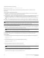
1
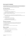
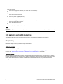
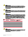
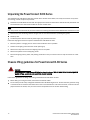
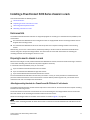
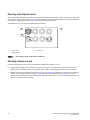
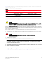
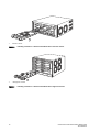
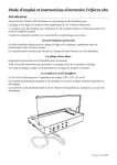
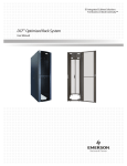
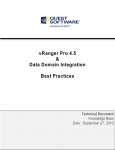
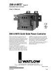
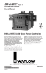
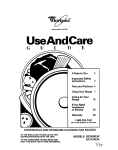
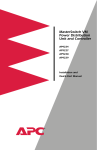
53-1001682-03
July 7, 2010
PowerConnect™ B-RX
Series
Getting Started Guide
53-1001682-03
*53-1001682-03*
Notes Cautions and Warnings
NOTE
A NOTE indicates important information that helps you make better use of your computer.
CAUTION
A Caution statement alerts you to situations that can be potentially hazardous to you or cause damage to
hardware, firmware, software, or data.
DANGER
A DANGER indicates a potential for property damage, personal injury, or death.
____________________
Information in this document is subject to change without notice.
© 2009-2010 Dell Inc. All rights reserved.
Reproduction of these materials in any manner whatsoever without the written permission of Dell Inc. is strictly forbidden.
Trademarks used in this text: Dell, the DELL logo, Inspiron, Dell Precision, Dimension, OptiPlex, Latitude, PowerEdge, PowerVault, PowerApp, and
DellOpenManage are trademarks of Dell Inc.; Intel, Pentium, and Celeron are registered trademarks of Intel Corporation in the U.S. and other
countries; Microsoft, Windows, Windows Server, MS-DOS and Windows Vista are either trademarks or registered trademarks of Microsoft
Corporation in the United States and/or other countries.
Other trademarks and trade names may be used in this document to refer to either the entities claiming the marks and names or their products
Dell Inc. disclaims any proprietary interest in trademarks and trade names other than its own.
Regulatory Models: BI-RX-4, BI-RX-8, and BI-RX-16.
2
PowerConnect B-RX Series Getting Started Guide
53-1001682-03
In this guide
• Introduction. . . . . . . . . . . . . . . . . . . . . . . . . . . . . . . . . . . . . . . . . . . . . . . . . . . .
• Four-slot chassis. . . . . . . . . . . . . . . . . . . . . . . . . . . . . . . . . . . . . . . . . . . . . . . .
• Eight-slot chassis . . . . . . . . . . . . . . . . . . . . . . . . . . . . . . . . . . . . . . . . . . . . . . .
• Items required for installation . . . . . . . . . . . . . . . . . . . . . . . . . . . . . . . . . . . . .
• Site planning and safety guidelines . . . . . . . . . . . . . . . . . . . . . . . . . . . . . . . .
• Unpacking the PowerConnect B-RX Series . . . . . . . . . . . . . . . . . . . . . . . . . .
• Chassis lifting guidelines for PowerConnect B-RX Series . . . . . . . . . . . . . .
• Installing a PowerConnect B-RX Series chassis in a rack . . . . . . . . . . . . . .
• Installing modules . . . . . . . . . . . . . . . . . . . . . . . . . . . . . . . . . . . . . . . . . . . . .
• Installing power supplies . . . . . . . . . . . . . . . . . . . . . . . . . . . . . . . . . . . . . . . .
• Connecting AC power . . . . . . . . . . . . . . . . . . . . . . . . . . . . . . . . . . . . . . . . . . .
• Connecting DC power. . . . . . . . . . . . . . . . . . . . . . . . . . . . . . . . . . . . . . . . . . .
• Managing cables . . . . . . . . . . . . . . . . . . . . . . . . . . . . . . . . . . . . . . . . . . . . . .
• Attaching a management station . . . . . . . . . . . . . . . . . . . . . . . . . . . . . . . . .
• Powering-on the power source . . . . . . . . . . . . . . . . . . . . . . . . . . . . . . . . . . .
• Verifying proper operation . . . . . . . . . . . . . . . . . . . . . . . . . . . . . . . . . . . . . . .
• Assigning passwords . . . . . . . . . . . . . . . . . . . . . . . . . . . . . . . . . . . . . . . . . . .
• Configuring IP addresses . . . . . . . . . . . . . . . . . . . . . . . . . . . . . . . . . . . . . . . .
• Connecting the PowerConnect B-RX Series to a network device . . . . . . . .
3
4
5
7
8
12
12
13
16
20
22
23
24
24
25
26
27
29
31
Introduction
This guide provides instructions for unpacking, installing, and setting up PowerConnect B-RX Series four-slot,
eight-slot, and 16-slot models in equipment racks. Note the following additional documentation:
• For detailed installation and configuration instructions, refer to your hardware installation guide.
• For rack-specific installation instructions, refer to the appropriate rack mount installation procedures.
The PowerConnect B-RX series consists of the following chassis models:
• Four-slot chassis, which provides four interface slots
• Eight-slot chassis, which provides eight interface slots
• 16-slot chassis, which provides 16 interface slots.
The PowerConnect B-RX Series can be installed in the following ways:
• In a 19-in. Electronic Industries Association cabinet (EIA310-D). The B-RX Series units have built-in mounting
brackets for installing in racks.
• In a mid-mount telecommunications (Telco) rack. A mid-mount kit can be ordered separately from your
PowerConnect supplier to center mount the PowerConnect unit in the rack. It contains two L-shaped mounting
brackets and instructions for installing the brackets and mounting the unit.
The basic configuration steps required to set up the PowerConnect B-RX Series are listed in this guide. Additional
configuration information is provided in the hardware installation manual.
PowerConnect B-RX Series Getting Started Guide
53-1001682-03
3
Four-slot chassis
The following figure illustrates the PowerConnect B-RX Series four-slot chassis and components location:
1
2
3
4
5
6
7
8
9
10
11
1
Interface slot 2
7
Interface slot 3
2
Switch fabric slot 2
8
Management slot 1
3
Switch fabric slot 3
9
Management slot 2
4
ESD connector
10
Interface slot 4
5
Interface slot 1
11
Fan tray assembly
6
Switch fabric slot 1
FIGURE 1
4
PowerConnect B-RX Series four-slot chassis
PowerConnect B-RX Series Getting Started Guide
53-1001682-03
Eight-slot chassis
The following figure illustrates the PowerConnect B-RX Series eight-slot chassis and components location.
1
2
4
3
5
7
6
9
8
11
10
13
12
19
14
15
16
1
Interface slot 1
11
Interface slot 8
2
Interface slot 2
12
Management slot 1
3
Interface slot 3
13
Management slot 2
4
Interface slot 4
14
Power supply slot 1
5
Switch fabric slot 1
15
Power supply slot 2
6
Switch fabric slot 2
16
Power supply slot 3
7
Switch fabric slot 3
17
Power supply slot 4
8
Interface slot 5
18
ESD connector
9
Interface slot 6
19
Fan tray assembly
10
Interface slot 7
FIGURE 2
17
18
PowerConnect B-RX Series eight-slot chassis
PowerConnect B-RX Series Getting Started Guide
53-1001682-03
5
16-slot chassis
The following figure illustrates the PowerConnect B-RX Series 16-slot chassis and components location.
1
3
5
7
17 19
9
11 13
12
14
23 15
21
22
2
4
6
8
18
20
10
1
Interface slot 1
13
Interface slot 13
2
Interface slot 2
14
Interface slot 14
3
Interface slot 3
15
Interface slot 15
4
Interface slot 4
16
Interface slot 16
5
Interface slot 5
17
Switch fabric slot 1
6
Interface slot 6
18
Switch fabric slot 2
7
Interface slot 7
19
Switch fabric slot 3
8
Interface slot 8
20
Switch fabric slot 4
9
Interface slot 9
21
Management slot 1
10
Interface slot 10
22
Management slot 2
11
Interface slot 11
23
ESD connector
12
Interface slot 12
FIGURE 3
6
16
PowerConnect B-RX Series-16-slot chassis
PowerConnect B-RX Series Getting Started Guide
53-1001682-03
Items required for installation
This document describes how to set up the PowerConnect B-RX series and mount into 19-inch equipment racks
using the brackets built onto each chassis. To center mount the chassis in a rack, order the mid-mount rack kit from
your PowerConnect supplier. Installation instructions are provided with the rack kit. This section describes items
shipped with the PowerConnect B-RX series and items you will need for installation.
Items shipped with units
The chassis ships with the following components installed:
• Switch fabric modules
- Four and eight-slot chassis - two switch fabric modules
- 16-slot chassis - three switch fabric modules
• A slot blank in each interface module slot. The slot blank covers a slot that does not currently have a module
installed in it, ensuring proper airflow within the chassis.
• Fans
- Four and eight-slot chassis - A fan tray assembly in the front right side of the chassis.
- 16-slot chassis - A fan tray assembly located in the front right side and two fan assemblies located at the
rear of the of the chassis.
• Power supplies (AC or DC).
- The four-slot chassis contains one power supply,
- The eight-slot chassis contains two power supplies.
- The 16-slot chassis contains four power supplies.
• A 115V AC power cable for each AC power supply you purchase.
Items that you must provide
•
•
•
•
•
Assembled 19-inch Electronic Industries Association cabinet (EIA310-D) equipment rack.
Four standard #12-24 pan-head screws for mounting the chassis to equipment racks.
#2 Phillips-head screwdriver.
Flat head screwdriver
Mid-mount rack kit (optional). Order from your PowerConnect supplier.
What you can install
You can install the following components in the different chassis slots.
• Four-slot chassis
- Up to two management modules (one active and one redundant).
- Up to three switch fabric modules.
- Up to four interface modules.
- Up to three power supplies (AC or DC).
PowerConnect B-RX Series Getting Started Guide
53-1001682-03
7
• Eight-slot chassis
- Up to two management modules (one active and one redundant).
- Up to three switch fabric modules.
- Up to eight interface modules.
- Up to four power supplies (AC or DC).
• 16-slot chassis
- Up to two management modules (one active and one redundant).
- Up to four switch fabric modules.
- Up to 16 interface modules.
- Up to eight power supplies (AC or DC).
NOTE
Before installing any modules or power supplies, you must remove the slot blank or blank power supply faceplate,
respectively.
Site planning and safety guidelines
The following steps and safety precautions are required to ensure correct installation and operation.
Site planning
Follow these steps to ensure your site is ready for installation.
Cabling infrastructure
Ensure that the proper cabling is installed in the site.
For information on cabling, refer to “Installing power supplies” on page 20, “Attaching a management station” on
page 24, and “Connecting the PowerConnect B-RX Series to a network device” on page 31.
Installation location
Before installing the switch, plan its location and orientation relative to other devices and equipment. For cooling
purposes, allow a minimum of 15.24 cm (6 in.) of space between the sides, front, and the back of the chassis and
walls or other obstructions. If a chassis is installed within a perforated enclosure, the perforations must have
openings of at least 60 percent of the surface.
8
PowerConnect B-RX Series Getting Started Guide
53-1001682-03
Safety guidelines
Before proceeding with installation, please read the cautions and warnings that apply to the PowerConnect B-RX
Series.
General precautions
DANGER
The procedures in this manual are for qualified service personnel.
DANGER
All fiber-optic interfaces use Class 1 Lasers.
CAUTION
See the safety and regulatory information that shipped with your system. For additional regulatory
information, see the Regulatory Compliance Homepage at www.dell.com/regulatory_compliance.
CAUTION
Do not install the device in an environment where the operating ambient temperature might exceed 40o
C (104o F).
CAUTION
Make sure the air flow around the front, sides, and back of the device is not restricted.
CAUTION
If you do not install a module in a slot, you must keep the slot blank in place. If you run the chassis with
an uncovered slot, the system may overheat.
CAUTION
Never leave tools inside the chassis.
PowerConnect B-RX Series Getting Started Guide
53-1001682-03
9
Power precautions
CAUTION
Use a separate branch circuit for each AC power cord, which provides redundancy in case one of the
circuits fails.
CAUTION
Make sure to choose the appropriate circuit device, depending on the number of AC power supplies
installed in the chassis.
DANGER
Disconnect the power cord from all power sources to completely remove power from the device.
DANGER
Make sure that the power source circuits are properly grounded, then use the power cord supplied with
the device to connect it to the power source.
DANGER
If the installation requires a different power cord than the one supplied with the device, make sure you
use a power cord displaying the mark of the safety agency that defines the regulations for power cords in
your country. The mark is your assurance that the power cord can be used safely with the device.
DANGER
Make sure the rack or cabinet housing the device is adequately secured to prevent it from becoming
unstable or falling over.
DANGER
Mount the devices you install in a rack or cabinet as low as possible. Place the heaviest device at the
bottom and progressively place lighter devices above.
10
PowerConnect B-RX Series Getting Started Guide
53-1001682-03
CAUTION
Ensure that the device does not overload the power circuits, wiring, and over-current protection. To
determine the possibility of overloading the supply circuits, add the ampere (amp) ratings of all devices
installed on the same circuit as the device. Compare this total with the rating limit for the circuit. The
maximum ampere ratings are usually printed on the devices near the input power connectors.
CAUTION
Devices with DC power sources are intended for installation in restricted access areas only. A restricted
access area is where access can be gained only by service personnel through the use of a special tool,
lock and key, or other means of security, and is controlled by the authority responsible for the location.
CAUTION
For a DC system, the gauge of wire will be determined by the power source as well as the power supply
draw (refer to Table 1). Use a grounding wire of at least 6 American Wire Gauge (AWG). The AWG wire
should be attached to an agency-approved crimp connector (provided on the PowerConnect B-RX Series
chassis), crimped with the proper tool. The single crimp connector should allow for securing to both
ground screws on the enclosure. Use a grounding wire of at least 6 AWG. For the grounding lug, use
UL-listed Panduit crimp connector, P/N LCD6-10A, and two 10-32, PPH screws to secure the crimp
connector to chassis. The grounding position is located on the side of chassis adjacent ground symbol.
TABLE 1
The American Wire Gauge (AWG) guidelines
AWG
Ohms per 100 feet
Maximum Amps for chassis wiring
Maximum Amps for power
transmission
5
0.3133
118
47
6
0.3951
101
37
7
0.4982
89
30
8
0.6282
73
24
9
0.7921
64
19
10
0.9989
55
15
11
1.26
47
12
12
1.588
41
9.3
CAUTION
For the DC input circuit to the system, make sure there is a UL-Listed 30 amp circuit breaker, minimum
-48Vdc, double pole, on the input to the terminal block. The input wiring for connection to the product
should be Listed copper wire, 8 AWG, marked VW-1, and rated minimum 9o C.
PowerConnect B-RX Series Getting Started Guide
53-1001682-03
11
Unpacking the PowerConnect B-RX Series
The PowerConnect B-RX Series ships with several items. Review the list below, and verify the contents. If any items
are missing, contact the place of purchase:
• PowerConnect B-RX Series chassis with the appropriate number of switch fabric modules already installed in the
slot marked SF and a slot blank installed in all other module slots.
NOTE
You must provide standard #12-24 pan-head screws for mounting the PowerConnect B-RX Series chassis into a rack.
• Web Pointer card containing software images and the user documentation (including this guide).
• Warranty card.
• A 115V AC power cable for each AC power supply you purchase from Dell.
Follow the steps given below to unpack a PowerConnect B-RX Series chassis.
1. Move the pallet to a staging area as close to the installation site as possible.
2. Position the shipping carton with the arrows pointing up.
3. Remove the strap that secures the shipping carton to the pallet.
4. Remove the plastic cover and shipping carton.
5. Save the shipping carton, pallet, and packing materials in case you need to move or ship the chassis at a later
time.
Chassis lifting guidelines for PowerConnect B-RX Series
DANGER
A fully-populated PowerConnect B-RX Series chassis is heavy. TWO OR MORE PEOPLE ARE REQUIRED
WHEN LIFTING, HANDLING, OR MOUNTING THESE DEVICES.
Follow these guidelines for lifting and moving a PowerConnect B-RX Series chassis:
• Before lifting or moving the switch, disconnect all external cables.
• Do not attempt to lift a fully configured PowerConnect B-RX Series eight-slot or 16-slot chassis by yourself. Using
a mechanical lift to maneuver the switch into a rack is recommended. If a lift cannot be used, a minimum of four
people must lift the switch, and you must remove components from the chassis before lifting.
12
PowerConnect B-RX Series Getting Started Guide
53-1001682-03
Installing a PowerConnect B-RX Series chassis in a rack
This section describes the following tasks:
•
•
•
•
“Rack mount kits”
“Preparing to mount a chassis in a rack”
“Removing extra shipment screws”
“Mounting a chassis in a rack”
Rack mount kits
The PowerConnect B-RX Series switches are shipped equipped for mounting in a standard 19-inch (EIA310-D) rack
as described:
• The PowerConnect B-RX Series four and eight-slot units are equipped with built-in mounting brackets and are
shipped with mounting screws.
• The PowerConnect B-RX Series 16-slot chassis ships with two L-shaped mounting brackets and mounting
screws.
Alternatively, you can use a mid-mount kit (ordered separately) to center-mount the PowerConnect B-RX Series
chassis using two L-shaped mounting brackets. The mid-mount kit comes with instructions for installing the
mounting brackets and mounting the device in a rack.
Preparing to mount a chassis in a rack
Because of the weight of a fully loaded PowerConnect B-RX Series chassis, Dell recommends mounting a chassis in
a rack before installing the modules and AC power supplies if necessary.
In a standard 19-inch (EIA310-D) rack, you can install
• Up to ten PowerConnect B-RX Series four-slot chassis.
• Up to six PowerConnect B-RX Series eight-slot chassis.
• Up to three PowerConnect B-RX Series sixteen-slot chassis.
For each PowerConnect B-RX Series chassis that you install in a rack, you must provide four standard #12-24
pan-head screws with which to mount and secure the chassis. Before performing this task, you should have an
assembled rack and a #2 Phillips-head screwdriver.
Attaching mounting brackets to a PowerConnect B-RX Series 16-slot chassis
The PowerConnect B-RX Series 16-slot chassis ships with a rack mount kit. The kit includes two L-shaped mounting
brackets and mounting screws.
The chassis sides have two sets of screw holes: one set for attaching the mounting brackets close to the chassis
front and another set for attaching the brackets toward the chassis center.
Attach the mounting brackets to the sides of the chassis as shown in Figure 7 on page 16.
NOTE
You can attach mounting brackets for either front-mount or mid-mount of the B PowerConnect B-RX Series 16-slot
chassis.
PowerConnect B-RX Series Getting Started Guide
53-1001682-03
13
Removing extra shipment screws
The PowerConnect B-RX Series four-slot and eight-slot chassis ships with two extra screws installed in the right side
of the chassis. These screws secure the fan tray, protecting it from damage during shipment. You must remove these
screws before installing the chassis. Figure 4 shows the location of the screws.
To perform this task, you need a #2 Phillips-head screwdriver.
1
2
3
1
Chassis front
2
Shipping screws
FIGURE 4
3
Chassis rear
Removing the extra screws used for shipment
Mounting a chassis in a rack
Follow the steps given below to mount a PowerConnect B-RX Series chassis in a rack.
1. Determine the position of each chassis in the rack, for example, a chassis with the fewest modules on top, a
chassis with more modules than the top chassis in the middle, and a fully populated chassis on the bottom.
2. Position two of the four screws for each chassis on the rack (Figure 5) according to the spacings of the keyhole
slots on the mounting brackets as shown in Figure 6 (four-slot and eight-slot chassis) or Figure 7 (16-slot
chassis). Do not secure the screws completely; leave approximately (.635 cm (1/4 in.) of clearance between the
back of the screw head and the rack.
14
PowerConnect B-RX Series Getting Started Guide
53-1001682-03
FIGURE 5
Positioning the screws in a rack
3. Starting with the chassis that you want to mount in the lowest position in the rack, mount the chassis in the rack
as shown in Figure 6 (four-slot and eight-slot chassis) or Figure 7 (16-slot chassis). With two or more people
lifting the chassis, slip the wide portion of each keyhole slot over the corresponding screw in the rack.
1
1
Standard 19 inch rack
FIGURE 6
Mounting the PowerConnect B-RX Series four-slot or eight-slot chassis in a rack
PowerConnect B-RX Series Getting Started Guide
53-1001682-03
15
1
FIGURE 7
Mounting the PowerConnect B-RX Series 16-slot chassis in a rack
4. Slide the chassis down so that the screw heads are in the narrow portion of the keyhole slots.
5. Tighten the screws to secure the chassis in place.
NOTE
To provide better grounding of the chassis to the rack, attach the chassis to the rack using star washers. Additionally,
if any single hole grounding lugs are used star washers shall be used as a means to prevent rotation of the lug.
6. Add additional screws as required.
7.
Repeat step 2 through step 6 to mount each subsequent chassis in the same rack.
Installing modules
This section provides one procedure that applies to all modules. The sequence for installing more than one module
is important to ensure proper fit. The recommended sequence for the PowerConnect B-RX Series chassis is to start
with the lowest row, moving upwards, from right-to-left. For the 16-slot chassis, refer to “Rules for populating a
PowerConnect B-RX Series-16 chassis” on page 19.
NOTE
The PowerConnect B-RX Series modules are dedicated, which means that you must install them in the PowerConnect
B-RX Series chassis only. For example, if you attempt to install the PowerConnect B-RX Series management module
in another Dell chassis or a management module intended for another Dell chassis in the PowerConnect B-RX Series
chassis, the chassis and module will not function properly.
16
PowerConnect B-RX Series Getting Started Guide
53-1001682-03
Table 2 provides the chassis slot numbers into which you must install the modules. Markings for the chassis slots
appear at the base of the slots.
TABLE 2
PowerConnect B-RX Series installation
PowerConnect B-RX Series
module
Chassis slot number (four-slot and eight-slot chassis)
Chassis slot number (16-slot chassis)
Management modules
Active module – M1 (left).
Redundant module – M2 (right).
Active module – M1 (upper).
Redundant module – M2 (lower).
Interface modules
1 – 4 (four-slot chassis)
1 – 8 (eight-slot chassis)
1 – 16 (16-slot chassis)
Switch fabric modules
SF1 – SF31
SF1 – SF41
1. Each PowerConnect B-RX Series chassis ships with the required switch fabric modules installed.You must purchase an additional
switch fabric element if you want your chassis equipped for redundancy.
CAUTION
If you do not install a module in a slot, you must leave the slot blank installed in the slot. If you run the
PowerConnect B-RX Series chassis with an uncovered slot, the system may overheat.
If you are installing a redundant management module, refer to the appropriate configuration guide for your product
for information about how the redundant module works, optional software configurations that you can perform, and
how to manage the redundancy feature.
Before installing a module in the PowerConnect B-RX Series chassis, have the following on hand:
• An ESD wrist strap with a plug for connection to the ESD connector on the PowerConnect B-RX Series chassis.
DANGER
For safety reasons, the ESD wrist strap should contain a 1 meg ohm series resistor.
• A large flat-head screwdriver.
Follow the steps given below to install a module in the PowerConnect B-RX Series chassis.
NOTE
The installation instructions for installing modules in the following steps are exactly the same for interface,
management, and switch fabric modules.
1. Put on the ESD wrist strap and ground yourself by inserting the plug into the ESD connector on the chassis front.
2. Remove the module from its packaging.
3. With the ejectors in the outward position, insert the module into the appropriate chassis slot and slide the card
along the card guide until the ejectors on either side of the module move close to the module front panel. Refer
to Figure 8 (four-slot chassis), Figure 9 (eight-slot chassis), and Figure 10 (16-slot chassis).
PowerConnect B-RX Series Getting Started Guide
53-1001682-03
17
1
1
Interface module
FIGURE 8
Installing a module in a PowerConnect B-RX Series four-slot chassis
1
1
Management module
FIGURE 9
18
Installing a module in a PowerConnect B-RX Series eight-slot chassis
PowerConnect B-RX Series Getting Started Guide
53-1001682-03
1
1
Interface module
FIGURE 10
Installing a module in a PowerConnect B-RX Series 16-slot chassis
NOTE
When inserting the module into the chassis, make sure that the faceplate does not overlap with the faceplate of
an adjacent interface module.
4. Push the ejectors in until they are flush with the module front panel. This action will fully seat the module in the
backplane. Modules have a snug fit for maximum EMI protection.
5. Tighten the two screws at either end of the module front panel by pushing them in and turning them clockwise.
Then, tighten the screws further using the flat-head screwdriver.
Rules for populating a PowerConnect B-RX Series-16 chassis
1. Install a management module in management slot 2.
2. Install interface modules in interface slots 2, 4, 6, and 8.
3. Install switch fabric modules in the switch fabric slots 2 and 4.
4. Install interface modules in interface slots 10, 12, 14, and 16.
5. Install a management module in management slot 1.
6. Install interface modules in interface slots 1, 3, 5, and 7.
7.
Install switch fabric modules in the switch fabric slots 1 and 3.
8. Install interface modules in interface slots 9, 11, 13, and 15.
PowerConnect B-RX Series Getting Started Guide
53-1001682-03
19
Installing power supplies
The PowerConnect B-RX Series accommodates multiple power supplies (AC or DC). Following are specifications for
the different models:
• Four-slot chassis - Accommodates three power supplies (AC or DC), with one required and two redundant. It is
shipped with one power supply. You must purchase one or two additional power supplies if you want your
four-slot chassis equipped for redundancy.
• Eight-slot chassis - Accommodates four power supplies (AC or DC), with two required and two redundant.
Because power is supplied over a common power bus, any power supply purchased in addition to the two
required will provide backup for any supply that fails. Equipping the chassis with two additional power supplies
provides full redundancy for both of the required power supplies.
• 16-slot chassis - Accommodates eight power supplies (AC or DC), with four required and four redundant.
Because power is supplied over a common power bus, any power supply purchased in addition to the four
required will provide backup for any supply that fails. Equipping a 16-slot chassis with four additional power
supplies provides full redundancy for all of the required power supplies.
Follow the steps given below to install a power supply in the PowerConnect B-RX Series chassis. You need a small
Phillips or flat-head screwdriver to perform this task.
1. Remove the blank power supply faceplate, and expose the empty power supply slot.
2. Remove the power supply from its packaging.
3. Insert the power supply into the empty power supply slot, using the guides provided on either side of the slot.
NOTE
Empty power supply slots should be covered with slot blanks.
CAUTION
Carefully follow the mechanical guides on each side of the power supply slot and make sure the power
supply is properly inserted in the guides. Never insert the power supply upside down.
4. For the four-slot chassis, follow these steps while referring to Figure 11 on page 21, then continue with step 6.
20
a.
Slide the power supply along the card guide until the ejectors on either side of the module move close to the
module front panel.
b.
After the power supply is fully inserted, push the power supply front panel toward the back of the chassis.
This action causes the power supply connector to seat into the backplane connector.
c.
Push the ejectors in until they are flush with the face of the power supply. This action will fully latch the
power supply in the backplane.
d.
Tighten the two screws at either end of the power supply front panel by pushing them in and turning them
clockwise. If desired, tighten the screws further using the flat-head screwdriver.
PowerConnect B-RX Series Getting Started Guide
53-1001682-03
1
1
Power supply
FIGURE 11
Installing power supply in a PowerConnect B-RX Series four-slot chassis
5. For the eight-slot and 16-slot chassis, follow these steps while referring to Figure 12 or Figure 13 on page 22
(depending on your chassis), then continue with step 6.
a.
Slide the card along the card guide until fully inserted, then push the power supply front panel toward the
back of the chassis. This action causes the power supply connector to latch into the backplane connector.
b.
Gently pull the handle on the power supply front panel upward and toward the top of the power supply front
panel. This action locks the power supply in place.
1
1
Power supply
FIGURE 12
Installing power supply in a PowerConnect B-RX Series eight-slot chassis
PowerConnect B-RX Series Getting Started Guide
53-1001682-03
21
1
2
1
Power supply
FIGURE 13
2
Release latch
Installing a power supply in a PowerConnect B-RX Series 16-slot chassis
6. For information about connecting power to the chassis, refer to “Connecting AC power” on page 22 or
“Connecting DC power” on page 23.
Connecting AC power
AC power is supplied through an AC power cord that is installed at the rear of the PowerConnect B-RX Series chassis.
1. Locate the power receptacle on the rear of the chassis, behind where AC power supplies are installed.
2. Lift the cord-retainer and connect a Dell-supplied AC power cord to the power supply.
3. Snap the cord-retainer over the power plug to hold it in place.
DANGER
If the installation requires a different power cord than the one supplied with the device, make sure you
use a power cord displaying the mark of the safety agency that defines the regulations for power cords in
your country. The mark is your assurance that the power cord can be used safely with the device.
4. For information about powering on the system, refer to “Powering-on the power source” on page 25.
22
PowerConnect B-RX Series Getting Started Guide
53-1001682-03
Connecting DC power
You can use a DC power source for the PowerConnect B-RX Series chassis. This is supported through use of a
DC-to-DC power supply. DC power must be supplied at 48 V and 30 A. The DC-to-DC supply provides the DC power to
the chassis at 12 V and 100 A.
DANGER
The procedure in this section is for qualified service personnel.
Follow the steps given below to connect a DC power source.
1. Use a flat-blade screwdriver to remove the two screws holding the transparent cover over the power supply lugs
(refer to Figure 14 and Figure 15 following).
1
DC DC ALM
IN OK
2
1
Screws holding power lugs
FIGURE 14
2
Screws holding transparent cover
DC power supply for four-slot chassis
1
DC IN
DC OUT ALM
2
1
Screws holding power lugs
FIGURE 15
2
Screws holding transparent cover
DC power supply for eight-slot and 16-slot chassis
2. Use a Phillips head screwdriver to remove each of the power lugs.
3. Crimp #8 AWG power supply wire into the power lugs and reconnect the power lugs to the power supply unit.
PowerConnect B-RX Series Getting Started Guide
53-1001682-03
23
1
1
#8 AWG power supply wire
FIGURE 16
Crimping the power supply wire in the lug
4. Re-attach the transparent cover over the power supply lugs that was removed in Step 1.
5. Connect the wire to your DC power source, making sure to connect the -48V cable to the negative terminal on
the power supply and the 0V cable to the positive terminal as marked on the power supply.
Managing cables
For information on managing cables attached to PowerConnect B-RX Series, refer to the chapter in your hardware
installation guide on using the structured cabling components.
Attaching a management station
You can manage the PowerConnect B-RX Series system in the following ways:
• You can connect a PC or terminal to the management module’s serial (Console) port for a direct connection.
From this interface, you can configure the 10BaseT/100BaseTX/1000BaseTX Ethernet (management) port with
an IP address and either Telnet or SSH. This enables you to manage the device through the
10BaseT/100BaseTX/1000BaseTX Ethernet (management) port using either Telnet or SSH.
• You can connect the PowerConnect B-RX Series switch to your existing management network and manage the
switch, along with other network devices, from a management station. To do this, you must connect the
management module’s 10BaseT/100BaseTX/1000BaseTX Ethernet (management) port to an Ethernet
network.
NOTE
The existing management network into which you can connect the 10/100 Ethernet port must be separate and
isolated from the network over which user packets are switched and routed.
For information about connecting a PC or terminal to the management module’s Console port or management port,
refer to “Attaching a PC or terminal to the Console port or Ethernet port” following. For information about connecting
a management port to a network, refer to “Attaching the management module’s Ethernet Port to a network” on
page 25.
24
PowerConnect B-RX Series Getting Started Guide
53-1001682-03
Attaching a PC or terminal to the Console port or Ethernet port
The management module’s Console port (which has a male DB-9 serial connector), and 10BaseT/100Base TX
Ethernet port (which has an RJ-45 UTP connector) allow you to attach a PC or terminal. From the Console port, you
can access the PowerConnect B-RX Series switch’s CLI directly from the PC or terminal or through a Telnet
connection to the PC or terminal. From the Ethernet port, you can access the PowerConnect B-RX Series switch’s CLI
or Web management interface directly from the PC or terminal or through a Telnet connection to the PC or terminal.
Before performing this task, you need the following items:
• PC running a terminal emulation application or a terminal.
• If connecting the PC or terminal to the Console port, a straight-through EIA or TIA DB-9 serial cable with one end
terminated in a female DB-9 connector and the other end terminated in a male or female DB-9 or DB-25
connector, depending on the specifications of your PC or terminal. You can order the serial cable separately from
Brocade or build your own cable. If you prefer to build your own, refer to your hardware installation guide.
• If connecting the PC or terminal to the Ethernet port, a Category 5 UTP crossover cable, which you must supply.
For information about the management port pin assignments, refer to your hardware installation guide.
Follow the steps given below to attach a PC or terminal to the Console port or Ethernet port.
1. Connect a PC or terminal to the Console port or Ethernet port using the appropriate cable.
2. Open the terminal emulation program, and set the session parameters as follows:
•
•
•
•
•
Baud: 9600 bps
Data bits: 8
Parity: None
Stop bits: 1
Flow control: None
Attaching the management module’s Ethernet Port to a network
The management module’s 10BaseT/100BaseTX/1000BaseTX Ethernet (management) port (RJ-45 UTP connector)
allows you to connect the management port to a network. A management station in your existing management
network can then access a PowerConnect B-RX Series switch using the switch’s Network Manager.
To attach the management module’s Ethernet port to a network, you need a Category 5 UTP straight-through cable
(not supplied by Dell). Connect one end of the straight-through cable to the management port and the other end to
the network.
Powering-on the power source
After you complete the hardware installation, you can power-on your power source.
1. Verify that all modules and power supplies are fully and properly installed and no module slots are uncovered.
CAUTION
If you do not install a module in a slot, you must keep the slot blank in place. If you run the chassis with
an uncovered slot, the system may overheat.
PowerConnect B-RX Series Getting Started Guide
53-1001682-03
25
2. If your power source is AC, attach one end of a Dell-supplied AC power cord to the AC power supply as described
in “Connecting AC power” on page 22.
Insert the other end into a 115V or 120V wall outlet. Repeat this step for each installed AC power supply.
DANGER
If the installation requires a different power cord than the one supplied with the device, make sure you
use a power cord displaying the mark of the safety agency that defines the regulations for power cords in
your country. The mark is your assurance that the power cord can be used safely with the device.
CAUTION
If the wall outlet is not rated 115/120V and 20A, you must have an electrician rewire the outlet and
power source. Make sure you obtain a power cord displaying the mark of the safety agency that defines
the regulations for power cords in your country. The mark is your assurance that the power cord can be
used safely with the device.
NOTE
The PowerConnect B-RX Series switch is designed to provide uninterrupted service even when you insert or
remove the management modules and the interface modules. Therefore, the system does not have a separate
on/off power switch. To turn the system off, simply unplug the power cords.
NOTE
The wall outlet should be installed near the equipment and should be easily accessible.
3. If you are supplying a DC power source to a PowerConnect B-RX Series chassis, attach the power cables to the
DC power supply as described in “Connecting DC power” on page 23.
Connect the other end of the cables to the DC power source. Repeat this step for each installed DC power
supply. Then switch on the power source.
4. Verify that the PowerConnect B-RX Series switch has initialized successfully. For information, refer to “Verifying
proper operation” on page 26.
Verifying proper operation
To verify the proper operation of the PowerConnect B-RX Series chassis after power on, you can do the following:
• Observe the LEDs
• Display the status of the modules using the CLI
Observing the LEDs
After a PowerConnect B-RX Series chassis powers on, you can observe its LEDs to verify that it initialized
successfully. Refer to your hardware installation guide for a complete description of the LEDs.
If a problem persists after taking action described in this table, contact technical support.
26
PowerConnect B-RX Series Getting Started Guide
53-1001682-03
Displaying the module status
After you have attached a PC or terminal to the management module’s Console port or Ethernet port and the
PowerConnect B-RX Series switch has initialized successfully, press Enter to display the following CLI prompt in the
terminal emulation window:
BigIron RX>
If you do not see this prompt, do the following.
1. Make sure the cable is securely connected to your PC or terminal and the Console port or Ethernet port.
2. Check the settings in your terminal emulation program. In addition to the session settings listed in “Attaching a
PC or terminal to the Console port or Ethernet port” on page 25, make sure the terminal emulation session is
running on the same serial port you attached to the Console port.
If you see this prompt (BigIron RX>), you are now connected to the system and can display the status of the modules
using the CLI. Enter the following command at any CLI level:
BigIron RX# show module
Module
M1 (upper): BigIron RX Mgmt Module
M2 (lower):
F0: BigIron RX Switch Fabric Module
S1:
S2:
S3:
S4: BigIron RX 4-Port 10Gig Module
S5: BigIron RX 4-Port 10Gig Module
S6: BigIron RX 4-Port 10Gig Module
S7:
S8:
Status
Active
Ports
Starting MAC
4
4
4
000c.db80.0000
000c.db80.0000
000c.db80.0000
Active
CARD_STATE_UP
CARD_STATE_UP
CARD_STATE_UP
Assigning passwords
DANGER
The procedures in this manual are for qualified service personnel.
Passwords can be up to 48 characters long. When you create an enable and a user password, you must enter a
minimum of eight characters containing the following combinations:
•
•
•
•
At least two upper case characters
At least two lower case characters
At least two numeric characters
At least two special characters
When you create a password, the characters you type are masked.
For example, to create a password for the enable login:
BigIron RX (config)#enable password TesT12$!
PowerConnect B-RX Series Getting Started Guide
53-1001682-03
27
To assign a password for a user account:
BigIron RX (config)#username sandy password [Enter]
Enter password: ********
Press the Enter key for [Enter]. Enter a password such as TesT12$! that contains the required character
combination.
The CLI contains the following access levels:
• User EXEC – The level you enter when you first start a CLI session. At this level, you can view some system
information but you cannot configure system or port parameters.
• Privileged EXEC – This level is also called the Enable level and can be secured by a password. You can perform
tasks such as manage files on the management module’s flash memory or a PCMCIA flash card in the
management module’s slots 1 or 2, save the system configuration to flash memory, and clear caches at this
level.
• CONFIG – The configuration level. This level lets you configure the system’s IP address and configure routing
features. To access the CONFIG mode, you must already be logged into the Privileged level of the EXEC mode.
NOTE
You cannot assign a password using the Web management interface. You can assign passwords using the switch’s
Network Manager if an Enable password for a Super User is already configured on the device.
You can set the following levels of Enable passwords:
• Super User – Allows complete read-and-write access to the system. This is generally for system administrators
and is the only password level that allows you to configure passwords.
NOTE
You must set a super user password before you can set other types of passwords.
• Port Configuration – Allows read-and-write access for specific ports but not for global (system-wide) parameters.
• Read Only – Allows access to the Privileged EXEC mode and CONFIG mode but only with read access.
To set passwords:
1. At the opening CLI prompt, enter the following command to change to the Privileged level of the EXEC mode:
BigIron RX> enable
BigIron RX#
2. Access the CONFIG level of the CLI by entering the following command:
BigIron RX# configure terminal
BigIron RX(config)#
3. Enter the following command to set the super-user password:
BigIron RX(config)# enable super-user-password <text>
NOTE
You must set the super-user password before you can set other types of passwords.
4. Enter the following commands to set the port configuration and read-only passwords:
BigIron RX(config)# enable port-config-password <text>
BigIron RX(config)# enable read-only-password <text>
28
PowerConnect B-RX Series Getting Started Guide
53-1001682-03
Configuring IP addresses
The PowerConnect B-RX Series switches implement separate data and control planes. This architecture affects how
you assign IP addresses. Table 3 outlines the interfaces to which you can assign IP addresses.
In this table, “in band” refers to an interface over which user packets are routed, while “out of band” refers to an
interface over which control packets related to system management are forwarded.
TABLE 3
Assigning IP addresses
Interface
Associated physical port
Out of band or
in band
Management interface
Ethernet 10/100/1000 port on active or
redundant management module
Out of band
Any interface over which user packets
are routed
Any interface module port
In band
Any virtual interface over which user
packets are routed
Any interface port
In band
Loopback interface
–
In band
This section describes the following:
• PowerConnect B-RX Series support of sub-net masks
• How to assign an IP address to a management interface
• How to assign an IP address to an interface or virtual interface over which user packets are routed
Support of sub-net masks
The PowerConnect B-RX Series switch supports both classical IP network masks (Class A, B, and C sub-net masks,
and so on) and Classless Interdomain Routing (CIDR) network prefix masks.
• To enter a classical network mask, enter the mask in IP address format. For example, enter
“209.157.22.99 255.255.255.0” for an IP address with a Class-C sub-net mask.
• To enter a prefix number for a network mask, enter a forward slash (/) and the number of bits in the mask
immediately after the IP address. For example, enter “209.157.22.99/24” for an IP address that has a network
mask with 24 significant (“mask”) bits.
Assigning an IP address to a management interface
Instead of assigning a global IP address to the PowerConnect B-RX Series switch for system management purposes,
you now assign an IP address to the management interface. The IP address is assigned to the active management
module port. If the active management module becomes unavailable and the redundant module becomes the active
module, the IP address is assigned to the new active management module port.
For example, to assign the IP address 10.0.1.1 to the management interface, do the following:
1. At the opening CLI prompt, enter enable.
BigIron RX> enable
PowerConnect B-RX Series Getting Started Guide
53-1001682-03
29
2. Enter the following command at the Privileged EXEC level prompt (for example, BigIron RX#), then press Enter.
This command erases the factory test configuration if still present:
BigIron RX# erase startup-config
CAUTION
Use the erase startup-config command only for new systems. If you enter this command on a system you
have already configured, the command erases the configuration. If you accidentally erase the
configuration on a configured system, enter the write memory command to save the running
configuration to the startup-config file.
3. Access the configuration level of the CLI by entering the following command:
BigIron RX# configure terminal
BigIron RX(config)#
4. Configure the IP address and mask for the management interface by entering the following commands:
BigIron RX(config)# interface management 1
BigIron RX(config-if-mgmt-1)# ip address 10.0.1.1 255.255.255.0
Assigning an IP address to an interface, virtual Interface, or loopback
You must assign an IP address to each interface and virtual interface over which user packets are routed. You can
also assign an IP address to a loopback interface, which is generally used for testing and diagnostic purposes.
You must use the serial connection to assign the first IP address. For subsequent addresses, you also can use the
CLI through Telnet or the Web management interface. You can use the switch’s Network Manager to assign IP
addresses to virtual routing interfaces only.
By default, you can configure up to 24 IP interfaces on each interface, virtual interface, and loopback interface.
For example, to assign the IP address 192.22.3.44 and sub-net mask 255.255.255.0 to Ethernet interface 1/1, do
the following.
1. At the opening CLI prompt, enter enable.
BigIron RX> enable
2. Enter the following command at the Privileged EXEC level prompt, then press Enter. This command erases the
factory test configuration if still present:
BigIron RX# erase startup-config
CAUTION
Use the erase startup-config command only for new systems. If you enter this command on a system you
have already configured, the command erases the configuration. If you accidentally erase the
configuration on a configured system, enter the write memory command to save the running
configuration to the startup-config file.
3. Access the configuration level of the CLI by entering the following command:
BigIron RX# configure terminal
BigIron RX(config)#
30
PowerConnect B-RX Series Getting Started Guide
53-1001682-03
4. Configure the IP address and sub-net mask for Ethernet interface 1/1 by entering the following commands:
BigIron RX(config)# interface ethernet 1/1
BigIron RX(config-if-e10000-1/1)# ip address 192.22.3.44 255.255.255.0
Use the secondary parameter if you have already configured an IP address within the same sub-net on the interface.
Enabling and disabling the interfaces
By default, all PowerConnect B-RX Series interfaces are disabled. To enable an interface, you must enter the enable
command at the appropriate interface configuration level of the CLI. For example, to enable the management
interface, enter the enable command at the management interface configuration level of the CLI:
BigIron RX(config-if-mgmt-1)# enable
You can disable each of these interfaces using the disable command at the appropriate interface configuration level
of the CLI. For example, to disable the management port, enter the disable command at the management interface
configuration level of the CLI:
BigIron RX (config-if-mgmt-1)# disable
Connecting the PowerConnect B-RX Series to a network device
You can connect a PowerConnect B-RX Series switch to another 10 Gigabit Ethernet network device. The
PowerConnect B-RX Series switch supports connections to other vendors’ as well as Dell devices.
The 10 Gigabit Ethernet interface module includes four ports where you can install fiber optic modules provided by
Dell. The SFP fiber optic modules provide an optical transceiver or a physical medium dependent (PMD) interface for
fiber that can be used with the LAN physical layer (PHY).
Table 4 outlines the fiber optic modules (PMDs) provided by Dell, the link distance associated with each, the cabling
needed to connect the PowerConnect B-RX Series switch to another network device, and the part number associated
with the module.
TABLE 4
Fiber optic modules and cabling
Fiber optic modules (PMD)
Distance
Fiber optic cabling
Short wavelength
850 nm serial
86 meters
300 meters
50/125 micron multimode fiber (500 Mhz km)
50/125 micron multimode fiber (2000 Mhz km)
Long wavelength
1310 nm serial
10 km
9/125 micron single-mode fiber with LC
connectors
Extra long wavelength
1550 nm serial
40 km
9/125 micron single-mode fiber with LC
connectors
NOTE
Cable installation and network configuration will affect overall transmission capability. The numbers provided above
represent the accepted recommendations of the various standards. For network-specific recommendations, consult
your local Dell reseller or system engineer.
PowerConnect B-RX Series Getting Started Guide
53-1001682-03
31
To connect a PowerConnect B-RX Series switch to another network device, you must do the following:
• Install the fiber optic modules
• Cable the fiber optic modules
Refer to your hardware installation guide for information about performing these tasks as well as cleaning the fiber
optic connectors and troubleshooting network connections.
Regulatory Notices
For additional regulatory information, see the Regulatory Compliance Homepage on www.dell.com at the following location:
www.dell.com/regulatory_compliance.
Información de la NOM (sólo para México)
La información que se proporciona a continuación aparece en el dispositivo descrito en este documento, en cumplimiento de los requisitos de la
Norma Oficial Mexican (NOM):
Importador:
Dell Inc. de Mexico, S.A. de C.V.
Paseo de la Reforma 2620-11o Piso
Col. Lomas Altas
11950 Mexico, D.F.
Equipos portatiles
Modelo
Voltaje de alimentación
Frecuencia
Consumo electrice
BI-RX-4
100-240 CA
50/60Hz
16A
BI-RX-8
100-240CA
50/60Hz
16A
BI-RX-16
100-240CA
50/60Hz
16A
Brocade DCX-4S
100-240CA
50-60Hz
15A
Brocade 8000
100-240CA
47-63Hz
5-2.5A
Informação sobre Órgão Regulador
A marca de certificação se aplica a este Equipamento de Rede de Dados
Para maiores consultas sobre ANATEL visite o site: www.anatel.gov.br
32
PowerConnect B-RX Series Getting Started Guide
53-1001682-03