1
book.book Page 1 Wednesday, March 9, 2011 3:11 PM
Dell PowerEdge M1000e
Systems
Configuration Guide
book.book Page 2 Wednesday, March 9, 2011 3:11 PM
Notes, Cautions, and Warnings
NOTE: A NOTE indicates important information that helps you make better use of
your computer.
CAUTION: A CAUTION indicates potential damage to hardware or loss of data if
instructions are not followed.
WARNING: A WARNING indicates a potential for property damage, personal
injury, or death.
____________________
Information in this publication is subject to change without notice.
© 2008–2011 Dell Inc. All rights reserved.
Reproduction of these materials in any manner whatsoever without the written permission of Dell Inc.
is strictly forbidden.
Trademarks used in this text: Dell™, the DELL logo, PowerEdge™, PowerConnect™, and
FlexAddress™ are trademarks of Dell Inc. Cisco® is a registered trademark of Cisco Systems, Inc.
Microsoft®, Windows®, and Active Directory® are registered trademarks of Microsoft Corporation
in the United States and/or other countries.
Other trademarks and trade names may be used in this publication to refer to either the entities claiming
the marks and names or their products. Dell Inc. disclaims any proprietary interest in trademarks and
trade names other than its own.
March 2011
Rev. A05
book.book Page 3 Wednesday, March 9, 2011 3:11 PM
Contents
1
About Your System
System Overview
LCD Module
. . . . . . . . . . . . . . . . . .
7
. . . . . . . . . . . . . . . . . . . . .
7
. . . . . . . . . . . . . . . . . . . . . . .
12
. . . . . . . . . . . . . . . . . .
14
. . . . . . . . . . . . . . . . . . . . . . . . . .
15
Back-Panel Features
Blades
CMC Module .
. . . . . . . . . . . . . . . . . . . . . .
iKVM Switch Module
23
. . . . . . . . . . . . . . . . . .
25
Initial System Configuration
Before You Begin
22
. . . .
CMC Daisy Chaining (Enclosure Stacking)
2
11
. . . . . . . . . . . . . . . .
LCD Module Menus
. . . . . . . . . .
27
. . . . . . . . . . . . . . . . . . . .
27
. . . . . . . . . . . . . . .
27
. . . . . . . . . . . . . . . .
27
. . . . . . . . . . . . . . . . .
27
. . . . . . . . . . . . . . . . . .
28
Power Requirements .
Network Information
Initial Setup Sequence
Configuring the CMC
. . . . . . . .
28
. . . . . . . . .
31
Initial CMC Network Configuration
Logging in to the CMC Using the
Web-Based Interface . . . . . .
Adding and Managing CMC Users .
. . . . . . . .
Configuring iDRAC Networking Using the
Web-Based Interface . . . . . . . . . .
. . . . .
Contents
32
33
3
book.book Page 4 Wednesday, March 9, 2011 3:11 PM
Setting the First Boot Device for Servers
Configuring and Managing Power
. . . . .
34
. . . . . . . . .
35
Installing or Updating the CMC Firmware
. . . . .
35
. . . .
38
. . . . . . . . .
38
. . . . . . . . . . .
38
Configuring the Optional iKVM Switch Module
Enabling iKVM Access to the Dell
CMC Console . . . . . . . . . . .
Updating the iKVM Firmware .
Tiering the Avocent iKVM Switch From an
Analog KVM Switch . . . . . . . . . . . .
. . . .
39
. . . . .
40
. . . . . . . . . .
41
. . . . . . . . . . . . . . . . . . . . . . .
43
Tiering the Avocent iKVM Switch From a
Digital KVM Switch . . . . . . . . . . . .
Viewing and Selecting Servers
FlexAddress
Activating FlexAddress .
3
. . . . . . . . . . . . . .
Configuring the I/O Modules
Overview .
. . . . . . . . . .
47
. . . . . . . . . . . . . . . . . . . . . . . .
47
Identifying Midplane Version .
Before You Begin
. . . . . . . . . . .
49
. . . . . . . . . . . . . . . . . . . .
52
. . . . . . . . . . . . . . . .
52
. . . . . . . . . . . . . . . . . . . . .
52
Network Information
Switch Modules
Configuring a Switch Module Network
Ethernet Port Using the
Web-Based Interface . . . . . . . . .
. . . . . .
52
. . . . . . .
53
. . . . . . . . . .
55
Dell PowerConnect-KR 8024-k Switch
Dell M8428-k 10 Gb Converged
Network Switch . . . . . . . .
4
Contents
44
Mellanox M2401G DDR Infiniband
Switch I/O Module . . . . . . . .
. . . . . . . . .
57
Mellanox M3601Q QDR Infiniband
Switch I/O Module . . . . . . . .
. . . . . . . . .
58
book.book Page 5 Wednesday, March 9, 2011 3:11 PM
Cisco SFS M7000e Infiniband
Switch I/O Module . . . . . .
. . . . . . . . . . .
Cisco Catalyst Ethernet Switch I/O Modules
PowerConnect M6220 Ethernet Switch
I/O Module . . . . . . . . . . . . . . .
60
. . .
61
. . . . . .
63
PowerConnect M6348 1 Gb Ethernet Switch
I/O Module . . . . . . . . . . . . . . . . . .
. . .
65
PowerConnect M8024 10 Gb Ethernet Switch
I/O Module . . . . . . . . . . . . . . . . . .
. . .
67
Brocade M4424 SAN I/O Module
. . . . . . . . .
69
. . . . . . . . . .
71
. . . . . . . . . . .
73
. . . . . . . . . . . . . . . . .
75
Brocade M5424 FC8 I/O Module
Dell 8/4 Gbps FC SAN Module
Pass-Through Modules
Dell 10 GbE KR Pass-Through I/O Module
. . . . .
Dell 8/4 Gbps Fibre Channel Pass-Through
I/O Module . . . . . . . . . . . . . . . . .
75
. . . .
77
10 Gb Ethernet Pass-Through Module II .
. . . . .
79
10 Gb Ethernet Pass-Through I/O Module
. . . . .
81
. . . . . .
83
10/100/1000 Mb Ethernet Pass-Through
I/O Module . . . . . . . . . . . . . . .
4G Fibre Channel Pass-Through I/O Module .
. . .
Contents
85
5
book.book Page 6 Wednesday, March 9, 2011 3:11 PM
6
Contents
book.book Page 7 Wednesday, March 9, 2011 3:11 PM
1
About Your System
System Overview
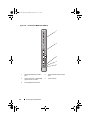
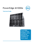
Your system can include up to 16 half-height blades (server modules), eight
full-height blades, or a mixture of the two blade types (see Figure 1-1,
Figure 1-2, and Figure 1-3). To function as a system, a blade is inserted into a
Dell PowerEdge M1000e enclosure (chassis) that supports power supplies, fan
modules, a Chassis Management Controller (CMC) module, and at least one
I/O module for external network connectivity. The power supplies, fans,
CMC, optional iKVM module, and I/O modules are shared resources of the
blades in the enclosure.
NOTE: To ensure proper operation and cooling, all bays in the enclosure must be
populated at all times with either a module or with a blank.
About Your System
7
book.book Page 8 Wednesday, March 9, 2011 3:11 PM
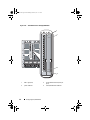
Figure 1-1. Blade Numbering—Half-Height Blades
8
1
2
3
4
5
6
7
9
10
11
12
13
14
15
About Your System
8
16
book.book Page 9 Wednesday, March 9, 2011 3:11 PM
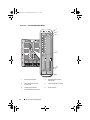
Figure 1-2. Blade Numbering—Full Height Blades
1
2
3
4
5
6
7
8
Figure 1-3. Blade Numbering—Mixed Full-Height and Half-Height Blades
1
2
3
4
5
13
6
14
7
8
15
16
About Your System
9
book.book Page 10 Wednesday, March 9, 2011 3:11 PM
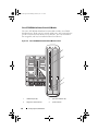
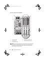
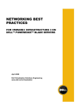
Figure 1-4 shows the control panel features on the M1000e enclosure panel.
Figure 1-4. Control Panel Features
1
2
3
4
5
1
USB port (mouse only)
2
USB port (keyboard only)
3
video connector
4
system power button
5
system power indicator
NOTE: The USB and video ports are functional only if an optional iKVM module is
installed.
10
About Your System
book.book Page 11 Wednesday, March 9, 2011 3:11 PM
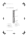
LCD Module
The LCD module provides an initial configuration/deployment wizard, as
well as access to infrastructure and blade information, and error reporting.
See Figure 1-5.
Figure 1-5. LCD Module
2
3
1
1
LCD screen
3
selection ("check") button
2
scroll buttons (4)
About Your System
11
book.book Page 12 Wednesday, March 9, 2011 3:11 PM
LCD Module Menus
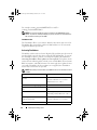
Table 1-1. LCD Module Screen Navigation Keys
Keys
Action
Left and right arrows
Use the left and right arrow keys to navigate through the
options in a menu and to scroll text.
Up arrow or down arrow
Use the up and down arrow keys to navigate through the
options in a menu, scroll text or increase a numerical
value.
Center button
Use this button to select a menu option.
Main Menu
The Main Menu options include links to the LCD Setup Menu, Server
Menu, and Enclosure Menu.
LCD Setup Menu
You can change the default language and start-up screen for the LCD menu
screens using this menu.
Server Menu
From the Server Menu dialog box, you can highlight each blade in the
enclosure using the arrow keys, and view its status.
12
•
A blade that is powered off or booting is designated by a gray rectangle. An
active blade is indicated by a green rectangle. If a blade has errors, this
condition is indicated by an amber rectangle.
•
To select a blade, highlight it and press the center button. A dialog box
displays the iDRAC IP address of the blade and any errors present.
About Your System
book.book Page 13 Wednesday, March 9, 2011 3:11 PM
Enclosure Menu
The Enclosure Menu includes options for Module Status, Enclosure Status,
and Network Summary.
•
In the Module Status dialog box, you can highlight each component in the
enclosure and view its status.
–
A module that is powered off or booting is designated by a gray
rectangle. An active module is indicated by a green rectangle. If a
module has errors, it is indicated by an amber rectangle.
–
If a module is selected, a dialog box displays the current status of the
module and any errors present.
•
In the Enclosure Status dialog box, you can view the enclosure status, any
error conditions, and power consumption statistics.
•
The Network Summary screen lists the IP addresses for the CMC, the
iDRAC in each blade, and other components in the enclosure.
About Your System
13
book.book Page 14 Wednesday, March 9, 2011 3:11 PM
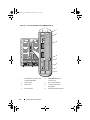
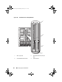
Back-Panel Features
The back panel of the M1000e enclosure supports six I/O modules, one or two
CMC modules, an optional iKVM module, nine fan modules, and six power
supply modules. Figure 1-6 shows a fully configured enclosure.
Figure 1-6. Back Panel Features
1
2
3
4
5
6
14
1
fan modules (9)
3
I/O modules (6)
4
optional iKVM module
5
secondary CMC module
6
power supplies (6)
About Your System
2
primary CMC module
book.book Page 15 Wednesday, March 9, 2011 3:11 PM
Blades
Figure 1-7. Front Panel Features—PowerEdge M910
1
2
6
5
4
3
1
blade-handle release button
2
hard drives (2)
3
blade status/identification indicator
4
USB connectors (3)
5
blade power button
6
blade power indicator
About Your System
15
book.book Page 16 Wednesday, March 9, 2011 3:11 PM
Figure 1-8. Front Panel Features—PowerEdge M905 and M805
1
2
6
5
4
3
16
1
blade handle release button
2
hard drives (2)
3
blade status/identification indicator
4
USB connectors (3)
5
blade power button
6
blade power indicator
About Your System
book.book Page 17 Wednesday, March 9, 2011 3:11 PM
Figure 1-9. Front Panel Features—PowerEdge M710HD
1
2
6
3
5
4
1
blade power indicator
2
blade handle release button
3
hard drives (2)
4
blade status/identification indicator
5
USB connectors (2)
6
blade power button
About Your System
17
book.book Page 18 Wednesday, March 9, 2011 3:11 PM
Figure 1-10. Front Panel Features—PowerEdge M710
1
2
6
5
4
3
1
18
blade handle release button
2
hard drives (4)
3
USB connectors (3)
4
blade status/identification indicator
5
blade power button
6
blade power indicator
About Your System
book.book Page 19 Wednesday, March 9, 2011 3:11 PM
Figure 1-11. Front Panel Features—PowerEdge M610x
1
8
7
2
6
5
3
4
1
blade handle release button
2
hard drives (2)
3
expansion-card filler-bracket
retention latch with captive screw
4
expansion-card slots (2)
5
blade status/identification indicator
6
USB connectors (2)
7
blade power button
8
blade power indicator
About Your System
19
book.book Page 20 Wednesday, March 9, 2011 3:11 PM
Figure 1-12. Front Panel Features—PowerEdge M610
1
6
5
4
3
2
20
1
blade handle release button
2
hard drives (2)
3
blade status/identification indicator
4
USB connectors (2)
5
blade power button
6
blade power indicator
About Your System
book.book Page 21 Wednesday, March 9, 2011 3:11 PM
Figure 1-13. Front Panel Features—PowerEdge M600 and M605
1
2
6
5
4
3
1
blade handle release button
2
hard drives (2)
3
blade status/identification indicator
4
USB connectors (2)
5
blade power button
6
blade power indicator
About Your System
21
book.book Page 22 Wednesday, March 9, 2011 3:11 PM
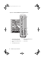
CMC Module
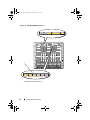
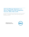
Figure 1-14. CMC Module Features
1
2
3
4
5
10
9
8
6
7
1
Ethernet connector Gb1
2
Ethernet connector STK (used for
daisy-chaining CMCs in separate
enclosures)
3
link indicator (2)
4
activity indicator (2)
5
DB-9 serial connector for local
configuration
6
optional secondary CMC (CMC 2)
7
primary CMC (CMC 1)
8
fault indicator
9
status/identification indicator
10
power indicator
The CMC provides multiple systems management functions for your
modular server, including the M1000e enclosure’s network and security
settings, I/O module and iDRAC network settings, and power redundancy and
power ceiling settings.
22
About Your System
book.book Page 23 Wednesday, March 9, 2011 3:11 PM
CMC Daisy Chaining (Enclosure Stacking)
CMC daisy chaining can be utilized to minimize the number of network
connections required for chassis (enclosure) management, such that only one
or two network connections (depending on whether or not redundant CMCs
are installed) are needed for up to four M1000e enclosures.
Cabling Guidelines
Follow these guidelines to daisy chain CMC modules from enclosure to
enclosure:
•
CMC Ethernet port GB1 is the Uplink port. It uplinks to either the
management network, or to receive a cable from the CMC Ethernet port
labeled STK in the adjacent enclosure.
The CMC Ethernet port labeled STK is the daisy-chain port. It connects
only to CMC port GB1 on the adjacent enclosure. Do not connect this
cable directly to the management network.
•
Up to four enclosures can be daisy chained.
•
Enclosures can be daisy chained in both redundant and non-redundant
deployments:
–
In a redundant CMC deployment, cable all CMC modules in the
CMC primary slots together. Cable all CMC modules in the CMC
secondary slots together.
NOTE: Do not connect the primary daisy chain with the secondary daisy
chain (do not cross cable the two sets of CMCs).
–
In a non-redundant CMC, cable all CMC modules in the CMC
primary slots together.
Figure 1-15 shows four enclosures with redundant CMC modules installed.
Primary CMC port GB1 in the first enclosure connects to the management
network. Primary CMC port GB1 in the adjacent enclosure is uplinked into
the port labeled STK on the primary CMC in the enclosure above it. No cable
is required in port STK on the fourth enclosure in line. The same cabling
scheme is valid for the daisy chain of CMC modules in the secondary slot of
the enclosures.
About Your System
23
book.book Page 24 Wednesday, March 9, 2011 3:11 PM
Figure 1-15. CMC Daisy Chaining—Enclosure With Redundant CMC Modules
1
2
3
24
1
management network segment
3
CMC2—cable from connector
Gb1 to network
About Your System
2
CMC1—cable from connector
Gb1 to network
book.book Page 25 Wednesday, March 9, 2011 3:11 PM
iKVM Switch Module
The optional Avocent iKVM analog switch module provides connections for a
keyboard, video (monitor), and mouse. It includes the following:
•
Local iKVM access can be remotely disabled on a per blade basis, using the
blade’s iDRAC interface (access is enabled by default).
NOTE: By default (enabled), a console session to a given blade is available to
both the iDRAC interface and an iKVM (user connected to a blade's console
through iDRAC and the iKVM sees the same video and be able to type
commands). Use the iDRAC console interface to disable the sharing of the
console session.
•
The following connectors:
–
One VGA connector. The iKVM supports a video display resolution range
from 640 x 480 at 60 Hz up to 1280 x 1024 x 65,000 colors at 75 Hz.
–
Two USB ports for keyboard and mouse.
–
RJ-45 ACI port for tiering with Dell and Avocent analog KVM and
KVM over IP switches with ARI ports.
NOTE: The iKVM USB ports do not support storage devices.
NOTE: Although the ACI port is an RJ-45 connector and uses Cat5 (or better)
cabling, it is not an Ethernet network interface port. It is only used for
connection to external KVM switches with Analog Rack Interface (ARI) ports,
and does not support native KVM over IP.
The iKVM can also be accessed from the front of the enclosure, providing
front or rear panel KVM functionality, but not at the same time. For
enhanced security, front panel access can be disabled using the CMC’s
interface.
NOTE: Connecting a keyboard, video, and mouse to the enclosure front panel
disables video output to the iKVM back-panel port. It does not interrupt iDRAC video
and console redirection.
You can use the iKVM to access the CMC using the Command Line
Interface. For more information, see "Using the iKVM Module" in the CMC
User’s Guide.
About Your System
25
book.book Page 26 Wednesday, March 9, 2011 3:11 PM
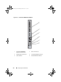
Figure 1-16 shows the external features of the iKVM module.
Figure 1-16. Avocent iKVM Switch Module
3
2
5
4
1
1
identification indicator
2
status indicator
3
ACI port for tiering connection
only
4
USB connectors (2) for keyboard
and mouse
5
video connector
CAUTION: Do not connect the ACI port to a LAN device such as a network hub.
Doing so may damage the equipment.
26
About Your System
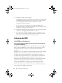
book.book Page 27 Wednesday, March 9, 2011 3:11 PM
Initial System Configuration
2
Before You Begin
Power Requirements
CAUTION: The enclosure power supplies must be connected to a Type B or
permanently-connected PDU and not directly to an electrical outlet. The power
supplies require a 100–120 V or 200–240 V power source. You can select only one
AC power input, as the system does not operate at both ranges simultaneously.
Network Information
If your network uses static addressing, you need the IP address, subnet mask,
and gateway to configure the CMC and other modules in the enclosure.
Initial Setup Sequence
1 Unpack the enclosure and install it in a rack.
For more information, see the Getting Started Guide and Rack Installation
Guide at support.dell.com/manuals.
CAUTION: Do not turn on the blades (server modules) until you have configured
the switch modules, as described in "Configuring the I/O Modules" on page 47.
2 Connect the power supply units to a PDU.
3 If an optional iKVM module is installed, connect the keyboard, video, and
mouse to the enclosure control panel (see Figure 1-4) or to the iKVM
module (see Figure 1-16).
NOTE: Connecting a keyboard, video, and mouse to the enclosure front panel
disables video output to the iKVM back panel port.
4 Press the power button on the enclosure control panel. See Figure 1-4.
Initial System Configuration
27
book.book Page 28 Wednesday, March 9, 2011 3:11 PM
5 Configure the CMC network settings.
The LCD Configuration Wizard allows you to quickly configure the CMC
and iDRAC management interfaces and manage the enclosure remotely.
See "Configuring the CMC Network Settings Using the LCD
Configuration Wizard" on page 28.
You can also use a management station and the RACADM CLI to
configure the CMC. See "Configuring the CMC Network Settings Using a
Management Station and CLI" on page 30.
6 Configure the IO modules to allow proper network or storage management
or paths. See "Configuring the I/O Modules" on page 47.
7 Once the Ethernet and Fibre Channel switches are configured, you can
power on your server blades. This allows time for the Ethernet switch to
boot and allow PXI \UNDI traffic for all blade modules.
Configuring the CMC
Initial CMC Network Configuration
Connecting to the CMC Using a Network Connection and the Default IP Address,
or a User-Defined IP Address
The CMC is preset for DHCP. To use a static IP address, you must toggle the
CMC setting from DHCP to a static address by either running the LCD
Configuration Wizard, or by using a management station and CLI
commands.
If toggled to use a static address, the CMC IP address defaults to the standard
IP address settings of 192.168.0.120, 255.255.255.0, and gateway of
192.168.0.1. You can change this address to an IP address of your choice.
For initial configuration instructions, see "Configuring the CMC Network
Settings Using the LCD Configuration Wizard" on page 28. To use a
management station/local connection and CLI, see "Configuring the CMC
Network Settings Using a Management Station and CLI" on page 30.
Configuring the CMC Network Settings Using the LCD Configuration Wizard
When you first start up your system, the screen on the LCD module directs
you to configure the CMC network settings.
28
Initial System Configuration
book.book Page 29 Wednesday, March 9, 2011 3:11 PM
NOTE: The option to configure the enclosure using the LCD Configuration Wizard is
only available until the CMC default password is changed or when the LCD
Configuration Wizard is complete. Thereafter, use the RACADM CLI or the webbased GUI to change the CMC settings (see "Configuring the CMC Network Settings
Using a Management Station and CLI" on page 30).
NOTE: The serial null modem cable for the CMC is an option. You can access the
CLI using the 17th Blade feature on the embedded iKVM module. Blade number 17 is
a direct local connection to the CMC.
1 Choose a language from the options presented in the dialog box.
2 Start the LCD Configuration Wizard.
3 Configure the CMC network settings for your network environment.
NOTE: The CMC external management network mode is set by default to
DHCP. To use a static IP address, you must change the setting using the LCD
Configuration Wizard.
–
Network speed
–
Duplex mode
–
Protocol (IPv4 and/or IPv6)
–
Network mode (DHCP or static)
–
Static IP address, subnet mask, and gateway values (if static mode was
selected)
–
DNS setting, including a registered CMC name, (if DHCP mode was
selected)
4 If required, configure the iDRAC network setting for DHCP mode.
NOTE: You cannot set a static IP address for the iDRAC using the LCD
Configuration Wizard. See "Configuring iDRAC Networking Using the WebBased Interface" on page 33.
Initial System Configuration
29
book.book Page 30 Wednesday, March 9, 2011 3:11 PM
5 Review the settings on the Network Summary screen.
–
If the settings are correct, press the center button to close the
configuration wizard and return to the Main Menu.
–
If the settings are not correct, use the left arrow key to return to the
screen for that setting and correct it.
The Network Summary screen lists the IP addresses for the CMC and the
iDRAC network settings.
After you complete the LCD Configuration Wizard, you can access the CMC
on the network using the Web-based CMC interface or text-based interfaces
such as a serial console, Telnet, or SSH.
Note that if you intend to use static addresses rather than DHCP to access
the iDRACs, you must configure them using the CMC Web-based interface
or CLI.
Configuring the CMC Network Settings Using a Management Station and CLI
The LCD Configuration Wizard is the quickest way to initially configure the
CMC network settings. However, you can also use a management station and
and a local connection to access the CMC. There are two ways to create a
local connection to the CMC:
•
The CMC Console using the optional iKVM. Press <Print Screen> and
select blade number 17.
•
Serial connection using an optional null modem cable (115200 bps, 8 data
bits, no parity, 1 stop bit, and no flow control).
Once you have established a connection to the CMC, you can complete the
initial CMC network configuration:
1 Log in to the CMC.
The default user name is root and the default password is calvin.
2 Type getniccfg and press <Enter> to view the current CMC network
parameters.
30
Initial System Configuration
book.book Page 31 Wednesday, March 9, 2011 3:11 PM
3 Configure the CMC network settings:
–
To set a static IP address, type
setniccfg -s<IP address><network mask><gateway>
and press <Enter>.
Use the appropriate settings for your network.
–
To configure the CMC to obtain an IP address using DHCP, type
setniccfg -d
and press <Enter>.
The new network settings are activated in a few seconds after configuring
the network.
Logging in to the CMC Using the Web-Based Interface
1 Open a supported Web browser window.
For more information, see "Supported Web Browsers" in the CMC User’s
Guide.
2 Log in to the CMC.
–
If the CMC is accessed using a specific IP address, type the following
URL in the Address field, and then press <Enter>:
https://<CMC IP address>
The default IP address for the CMC is 192.168.0.120. If the default
HTTPS port number (port 443) has been changed, type:
https://<CMC IP address>:<port number>
where <IP address> is the IP address for the CMC and port
number is the HTTPS port number.
–
If you access the CMC using a registered DNS name, type the CMC’s
name:
https://<CMC name>
By default, the CMC name on the DNS server is cmc-<service
tag>.
The CMC Login page is displayed.
Initial System Configuration
31
book.book Page 32 Wednesday, March 9, 2011 3:11 PM
NOTE: The default CMC user name is root, and the password is calvin. The
root account is the default administrative account that ships with the CMC. For
added security, you should change the default password of the root account during
initial setup.
NOTE: The CMC does not support extended ASCII characters, such as ß, å, é, ü, or
other characters used primarily in non-English languages.
NOTE: You cannot log in to the Web-based interface with different user names in
multiple browser windows on a single workstation.
You can log in as either a CMC user or as Directory Service user in
Microsoft Active Directory or Lightweight Directory Access Protocol
Services (LDAP).
3 In the Username field, type your user name:
–
CMC user name: <user name>
–
Active Directory user name: <domain>\<user name>,
<domain>/<user name> or <user>@<domain>.
–
LDAP user name: <user name>
NOTE: This field is case sensitive.
4 In the Password field, type your CMC user password or Active Directory
user password.
NOTE: This field is case-sensitive.
Adding and Managing CMC Users
From the Users and User Configuration pages in the Web-based interface,
you can view information about CMC users, add a new user, and change
settings for an existing user.
NOTE: For added security, it is highly recommended that you change the default
password of the root (User 1) account. The root account is the default
administrative account that ships with the CMC.
To change the default password for the root account, click User ID 1 to open
the User Configuration page. Help for that page is available through the Help
link at the top right corner of the page.
NOTE: You must have User Configuration Administrator privileges to perform the
following steps.
32
Initial System Configuration
book.book Page 33 Wednesday, March 9, 2011 3:11 PM
1 Log in to the Web-based interface. See "Logging in to the CMC Using the
Web-Based Interface" on page 31.
2 Select Chassis in the system tree.
3 Click the Network/Security tab, and then click the Users sub-tab. The
Users page appears, listing each user’s user ID, login state, user name, and
CMC privilege, including those of the root user. User IDs available for
configuration have no user information displayed.
4 Click an available user ID number. The User Configuration page is
displayed.
To refresh the contents of the Users page, click Refresh. To print the
contents of the Users page, click Print.
5 Select general settings for the users.
For details on user groups and privileges, see "Adding and Configuring
Users" in the CMC User’s Guide.
6 Assign the user to a CMC user group.
When you select a user privilege setting from the CMC Group drop-down
menu, the enabled privileges (shown as checked boxes in the list) are
displayed according to the pre-defined settings for that group.
You can customize the privileges settings for the user by using the check
boxes. After you have selected a CMC Group or made Custom user
privilege selections, click Apply Changes to save the settings.
Configuring iDRAC Networking Using the Web-Based Interface
Follow this procedure if you did not configure the iDRAC in the LCD
Configuration Wizard.
NOTE: If you did not configure the iDRAC using the LCD Configuration Wizard, the
iDRAC is disabled until you configure it using the Web-based interface
NOTE: You must have Chassis Configuration Administrator privileges to set up
iDRAC network settings from the CMC.
NOTE: The default CMC user name is root and the default password is calvin.
1 Log in to the Web-based interface. See "Logging in to the CMC Using the
Web-Based Interface" on page 31.
Initial System Configuration
33
book.book Page 34 Wednesday, March 9, 2011 3:11 PM
2 Click the plus (+) symbol next to Chassis in the left column, then click
Servers.
3 Click Setup Deploy.
4 Select the protocol for the iDRAC setting (IPv4 and/or IPv6).
5 Enable the LAN for the iDRAC on the server by selecting the check box
next to the server beneath the Enable Lan heading.
6 Enable or disable IPMI over LAN by using the check box next to the server
under the Enable IPMI over LAN heading.
7 Enable or disable DHCP for the iDRAC by checking or unchecking the
check box next to the server under the DHCP Enabled heading.
8 If DHCP is disabled, enter the static IP address, netmask, and default
gateway for the iDRAC.
9 Click Apply at the bottom of the page.
Setting the First Boot Device for Servers
The First Boot Device page allows you to specify the boot device for each
blade. You can set the default boot device and you can also set a one-time
boot device so that you can boot a special image to perform tasks such as
running diagnostics or reinstalling an operating system.
To set the first boot device for some or all servers in the chassis:
1 Log in to the CMC Web-based interface.
2 Click Servers in the system tree and then click Setup Deploy First Boot
Device. A list of servers is displayed, one per row.
3 Select the boot device you want to use for each server from the list box.
4 If you want the server to boot from the selected device every time it boots,
unselect the Boot Once check box for the server.
If you want the server to boot from the selected device only on the next
boot cycle, select the Boot Once check box for the server.
5 Click Apply.
34
Initial System Configuration
book.book Page 35 Wednesday, March 9, 2011 3:11 PM
Configuring and Managing Power
You can use the Web-based and RACADM interfaces to manage and
configure power controls on the CMC, as outlined in the following sections.
For detailed information on the various power management options, see
"Power Management" in the CMC User’s Guide.
Configuring Power Budget and Redundancy
The CMC’s power management service optimizes power consumption for the
entire chassis (the chassis, servers, I/O modules, iKVM, CMC, and PSUs) and
re-allocates power to different modules based on the demand.
NOTE: To perform power management actions, you must have Chassis Control
Administrator privileges.
1 Log in to the CMC Web-based interface.
2 Select Chassis in the system tree.
3 Click the Power Management tab. The Power Budget Status page is
displayed.
4 Click the Configuration sub-tab. The Budget/Redundancy Configuration
page is displayed.
5 Configure the power budget and redundancy settings based on the
components in the enclosure and your needs.
6 Click Apply to save your changes.
Installing or Updating the CMC Firmware
NOTE: It is normal for some or all of the fan units to spin at 100 percent during CMC
or iDRAC firmware updates on a server.
Updating Firmware in a Redundant CMC Configuration
NOTE: In redundant CMC configuration, care must be taken to update CMC
firmware on both modules. Failure to do so may cause unexpected behavior during
a CMC failover or failback. Use the following procedure for redundant CMC
deployments.
Initial System Configuration
35
book.book Page 36 Wednesday, March 9, 2011 3:11 PM
1 Locate the secondary or standby CMC by using the RACADM getsysinfo
command, or by using the Chassis Summary page in the Web-based
interface. Visually, the status indicator is solid blue on the primary or
active CMC module and off on the standby or secondary CMC (see
Figure 1-14).
2 Update the firmware on the standby CMC first. See "Updating the CMC
Firmware Using the Web-Based Interface" on page 37 or "Updating the
CMC Firmware Using RACADM" on page 37.
3 Verify that the secondary or standby CMC’s firmware is at the requested
level with the getsysinfo command or through the Web-based interface.
4 After the standby CMC has rebooted, update the firmware on the active or
primary CMC. Please allow 10 minutes for the standby CMC to boot.
See "Updating the CMC Firmware Using the Web-Based Interface" on
page 37 or "Updating the CMC Firmware Using RACADM" on page 37.
5 Verify that the active or primary CMC firmware is at the requested level
using the getsysinfo command or through the Web-based interface.
6 Once both CMCs are updated to the same firmware revision, use the
cmcchangeover command to reset the CMC in the left slot as primary.
Downloading the CMC Firmware
Before beginning the firmware update, download the latest firmware version
from support.dell.com, and save it to your local system.
The following software components are included with your CMC firmware
package:
•
Compiled CMC firmware code and data
•
Web-based interface, JPEG, and other user interface data files
•
Default configuration files
Use the Firmware Update page to update the CMC firmware to the latest
revision. When you run the firmware update, the update retains the current
CMC settings.
NOTE: The firmware update, by default, retains the current CMC settings. During
the update process, you have the option to reset the CMC configuration settings
back to the factory default settings.
36
Initial System Configuration
book.book Page 37 Wednesday, March 9, 2011 3:11 PM
Updating the CMC Firmware Using the Web-Based Interface
1 Log in to the Web-based interface. See "Logging in to the CMC Using the
Web-Based Interface" on page 31.
2 Click Chassis in the system tree.
3 Click the Update tab. The Updatable Components page is displayed.
4 On the Updatable Components page, click the CMC name. The
Firmware Update page is displayed.
5 In the Value field, type the path on your management station or shared
network where the firmware image file resides, or click Browse to navigate
to the file location.
NOTE: The default CMC firmware image name is firmimg.cmc and the
filename should not be changed. Care must be taken to keep different
firmware revisions separated as the file name always remains the same.
6 Click Update. A dialog box appears asking you to confirm the action.
7 Click Yes to continue. The firmware transfer process begins and the status
displays the message Firmware Update in Progress. Once the
CMC update is complete, the CMC is reset. Once the reset is complete,
you must refresh the User Interface page to then log in again.
Updating the CMC Firmware Using RACADM
1 Open a CMC command line console and log in.
2 Type:
racadm fwupdate -g -u -a <TFTP server IP address>
-d <filepath> -m <cmc-active|cmc-standby>
See the latest Dell Chassis Management Controller User's Guide at
support.dell.com/manuals for complete instructions on how to configure and
operate the CMC module.
Initial System Configuration
37
book.book Page 38 Wednesday, March 9, 2011 3:11 PM
Configuring the Optional iKVM Switch Module
Enabling iKVM Access to the Dell CMC Console
Enabling access to the CMC allows you to access the CMC directly and
securely through the iKVM’s CMC Console option. To enable the CMC
Console using the Web-based interface:
1 Log in to the CMC Web-based interface.
2 Select iKVM in the system tree. The iKVM Status page is displayed.
3 Click the Setup tab. The iKVM Configuration page is displayed.
4 Select Allow access to CMC CLI from iKVM.
5 Click Apply to save the setting.
Updating the iKVM Firmware
NOTE: The iKVM resets and becomes temporarily unavailable after the firmware
has been uploaded successfully.
1 Log in to the CMC’s Web-based interface. See "Logging in to the CMC
Using the Web-Based Interface" on page 31.
2 Select Chassis in the system tree.
3 Click the Update tab. The Updatable Components page is displayed.
4 Click the iKVM name. The Firmware Update page is displayed.
5 In the Value field, type the path on your management station or shared
network where the firmware image file resides, or click Browse to navigate
to the file location.
NOTE: The default iKVM firmware image name is ikvm.bin. However, the
iKVM firmware image name can be renamed. If you are unable to locate
ikvm.bin, determine whether another user has renamed the file.
6 Click Update. A dialog box appears asking you to confirm the action.
7 Click Yes to continue.
When the update is complete, the iKVM resets.
38
Initial System Configuration
book.book Page 39 Wednesday, March 9, 2011 3:11 PM
Tiering the Avocent iKVM Switch From an Analog KVM Switch
The Avocent iKVM switch can be tiered from analog KVM switches such as
the Dell 2160AS and 180AS, as well as many Avocent analog KVM switches.
Many switches may be tiered without the need for a Server Interface Pod
(SIP) (see Table 2-1).
Table 2-1. Cabling Requirements for External Analog KVM Switches
Switch
Tiering Cabling Requirements
Dell PowerConnect 180AS, 2160AS
(version 1.0.3.2 or later)
Seamless tiering using ACI port and
Cat 5 cable
Avocent Autoview 2020, 2030
(version 1.6.0.4 or later)
Avocent Autoview 1400, 1500, 2000,
1415, 1515, 2015
Avocent USB SIP (DSRIQ-USB)
required with Cat 5 cable
Before connecting the iKVM switch to a supported analog switch, you must
set the iKVM switch to display in slot order, and set the Screen Delay Time
to 1 or more seconds:
1 Press <Print Screen> to launch the iKVM Switch OSCAR.
2 Click Setup Menu. The Menu dialog box is displayed.
3 Select Slot to display servers numerically by slot number.
4 Enter a screen delay time of at least 1 second.
5 Click OK.
Setting the Screen Delay time to 1 second allows you to soft switch to a server
without launching OSCAR.
NOTE: Soft switching allows you to switch servers using a hot key sequence. You
can soft switch to a server by pressing <Print Screen> and then typing the first few
characters of its name or number. If you have a Delay Time set and you press the
key sequences before that time has elapsed, OSCAR does not display.
To configure the analog switch:
1 Press <Print Screen> to open the OSCAR Main dialog box.
2 Click Setup Devices Device Modify.
3 Select the 16-port option to match the number of blades in your system.
Initial System Configuration
39
book.book Page 40 Wednesday, March 9, 2011 3:11 PM
4 Click OK to exit OSCAR.
5 Press <Print Screen> to verify that the settings have taken effect. The slot
number of the blade to which the iKVM switch is now attached should be
expanded to display each of the slot locations of the blades in the system.
For instance, if the iKVM switch is attached to slot 1, it would now be
displayed as 01-01 to 01-16.
To connect the Avocent iKVM switch to a supported analog switch:
1 If the switch does not require a SIP to connect to the iKVM (see Table 2-1),
connect a Cat5 (or newer) cable to the RJ-45 ACI port on the iKVM
module. See Figure 1-16.
Connect the other end of this cable to the ARI port on the external switch.
If the analog switch requires a USB SIP (see Table 2-1), connect an Avocent
USB SIP to the iKVM, then connect a Cat5 (or newer) cable to the SIP.
Connect the other end of this cable to the ARI port on the external switch.
2 Connect both the analog switch and the system to an appropriate power
source.
3 Turn on the system.
4 Turn on the external analog switch.
NOTE: If the external analog switch is powered up before the system, it may result
in only one blade being displayed in the analog switch OSCAR, instead of 16. If this
behavior occurs, shut down and restart the switch so the entire complement of
blades is recognized.
NOTE: In addition to the steps outlined above, some external analog switches may
require you to perform additional steps to ensure that the iKVM switch blades
appear in the external analog switch OSCAR. See the external analog switch
documentation for additional information.
Tiering the Avocent iKVM Switch From a Digital KVM Switch
The iKVM module may also be tiered from a digital KVM switch such as the
Dell 2161DS-2 or 4161DS, or a supported Avocent digital KVM switch. Many
switches may be tiered without the need for a SIP (see Table 2-2).
40
Initial System Configuration
book.book Page 41 Wednesday, March 9, 2011 3:11 PM
Table 2-2. Cabling Requirements for External Digital KVM Switches
Switch
Tiering Requirements
Dell PowerConnect 2161DS,
4161DS, 2161DS-2, 2321DS
(version 1.3.40.0 or later)
Seamless tiering using ACI port
and Cat 5 cable
Avocent DSR x02x (except 1024),
x03x (version 3.6 or later)
Avocent DSR 800, x16x, x010,
1024
Avocent USB SIP (DSRIQ-USB)
required with Cat 5 cable
To tier the iKVM module from a Dell 2161DS, 180AS, or 2160AS console
switch:
•
If the switch does not require a SIP to connect to the iKVM (see Table 2-2),
connect a Cat5 (or newer) cable to the RJ-45 ACI port on the iKVM
module. See Figure 1-16.
Connect the other end of this cable to the ARI port on the external switch.
•
If the switch requires a USB SIP (see Table 2-1), connect an Avocent USB
SIP to the iKVM, then connect a Cat5 (or newer) cable to the SIP. Connect
the other end of this cable to the ARI port on the external switch.
Once the KVM switch is connected, the server modules appear in OSCAR.
NOTE: When the local system is set up, you must also resynchronize the server list
from the Remote Console Switch software in order to see the list of blades. See
"Resynchronizing the Server List at the Remote Client Workstation" on page 42.
Viewing and Selecting Servers
Use the OSCAR Main dialog box to view, configure, and manage servers in
the M1000e enclosure through the iKVM. You can view the servers by name
or by slot. The slot number is the chassis slot number the server occupies. The
Slot column indicates the slot number in which a server is installed.
NOTE: Server names and slot numbers are assigned by the CMC.
NOTE: If you have enabled access to the CMC though the iKVM, an additional
option, Dell CMC Console, is displayed. To enable this feature, see "Enabling iKVM
Access to the Dell CMC Console" on page 38.
Initial System Configuration
41
book.book Page 42 Wednesday, March 9, 2011 3:11 PM
To access the Main dialog box:
Press <Print Screen> to launch the OSCAR interface. The Main dialog box is
displayed.
or
If a password has been assigned, the Password dialog box is displayed. Type
your password and click OK. The Main dialog box is displayed.
Resynchronizing the Server List at the Remote Client Workstation
Once the iKVM module is connected, the blades appear in OSCAR. You now
need to resynchronize the servers on any remote workstation to ensure that
the blades are available to any remote users connected to the console switch
through the Remote Console Switch software.
NOTE: This procedure only resynchronizes one remote client workstation. With
multiple client workstations, save the resynchronized local database and load it into
the other client workstations to ensure consistency.
To resynchronize the server listing:
1 Click Resync in the Server category of the Management Panel (MP).
The Resync Wizard launches.
2 Click Next.
A warning message appears indicating that the database will be updated to
match the current configuration of the console switch. Your current local
database names will be overwritten with the switch names. To include
unpowered SIPs in the resynchronization, click to enable the Include
Offline SIPs check box.
3 Click Next.
A Polling Remote Console Switch message box appears with a progress
bar indicating that the switch information is being retrieved.
4 If no changes were detected in the appliance, a completion dialog box
appears with this information.
If server changes were detected, then the Detected Changes dialog box is
displayed. Click Next to update the database.
5 If a cascade switch was detected, the Enter Cascade Switch Information
dialog box is displayed.
42
Initial System Configuration
book.book Page 43 Wednesday, March 9, 2011 3:11 PM
6 Select the type of switch connected to the appliance from the drop-down
list. If the type you are looking for is not available, you can add it by
clicking Add.
7 Click Next. The completion dialog box is displayed.
8 Click Finish to exit.
9 Start up the analog switch and the system.
FlexAddress
The FlexAddress feature is an optional upgrade introduced in CMC 1.1 that
allows server modules to replace the factory assigned World Wide Name and
Media Access Control (WWN/MAC) network IDs with WWN/MAC IDs
provided by the chassis.
Every server module is assigned unique WWN and MAC IDs as part of the
manufacturing process. Before the FlexAddress feature was introduced, if you
had to replace one server module with another, the WWN/MAC IDs would
change and Ethernet network management tools and SAN resources would
need to be reconfigured to be aware of the new server module.
FlexAddress allows the CMC to assign WWN/MAC IDs to a particular slot
and override the factory IDs. If the server module is replaced, the slot-based
WWN/MAC ID remains the same. This feature eliminates the need to
reconfigure Ethernet network management tools and SAN resources for a new
server module.
Additionally, the override action only occurs when a server module is inserted
in a FlexAddress enabled chassis; no permanent changes are made to the
server module. If a server module is moved to a chassis that does not support
FlexAddress, the factory assigned WWN/MAC IDs are used.
Prior to installing FlexAddress, you can determine the range of MAC
addresses contained on a FlexAddress feature card by inserting the SD card
into an USB Memory Card Reader and viewing the file pwwn_mac.xml. This
clear text XML file on the SD card contains an XML tag mac_start, which is
the first starting hex MAC address that will be used for this unique MAC
address range. The mac_count tag is the total number of MAC addresses that
the SD card allocates. The total MAC range allocated can be determined by:
<mac_start> + 0xCF (208 - 1) = mac_end
Initial System Configuration
43
book.book Page 44 Wednesday, March 9, 2011 3:11 PM
For example:(starting_mac)00188BFFDCFA + 0xCF =
(ending_mac)00188BFFDDC9
NOTE: You must lock the SD card prior to inserting in the USB "Memory Card
Reader" to prevent accidently modifying any of the contents. You must unlock the
SD card before inserting into the CMC.
FlexAddress Plus
The FlexAddress Plus is a new feature added to the feature card version 2.0.
FlexAddress Plus expands the number of MAC addresses to 3136 from the
original FlexAddress pool of 208.
Activating FlexAddress
FlexAddress is delivered on a Secure Digital (SD) card that must be inserted
into the CMC to provide the chassis-assigned WWN/MAC IDs. To activate
the FlexAddress feature, perform several required updates; if you are not
activating FlexAddress, these updates are not required. The updates, which
are listed in the following table, include server module BIOS, I/O mezzanine
BIOS or firmware, and CMC firmware. You must apply these updates before
you enable FlexAddress. If these updates are not applied, the FlexAddress
feature may not function as expected.
NOTE: All systems purchased after June 2008 have the correct firmware versions
installed.
Component
Minimum Required Version
Ethernet mezzanine card - Broadcom
M5708t
Boot code firmware 4.4.1 or later
iSCSI boot firmware 2.7.11 or later
PXE firmware 4.4.3 or later
FC mezzanine card - QLogic QME2472 BIOS 2.04 or later
FC mezzanine card - Emulex LPe1105M4
BIOS 3.03a3 and firmware 2.72A2 or
later
Server Module BIOS
(PowerEdge M600) BIOS 2.02 or later
(PowerEdge M605) BIOS 2.03 or later
PowerEdge M600/M605 LAN on
motherboard (LOM)
Boot code firmware 4.4.1 or later
iDRAC
Version 1.11 or later
44
Initial System Configuration
iSCSI boot firmware 2.7.11 or later
book.book Page 45 Wednesday, March 9, 2011 3:11 PM
Component
Minimum Required Version
CMC
Version 1.10 or later
NOTE: Components not appearing in the above table require no updates to enable
the FlexAddress feature.
Activating FlexAddress Plus
FlexAddress Plus is delivered on the FlexAddress Plus Secure Digital (SD)
card along with the FlexAddress feature.
NOTE: The SD card labeled FlexAddress only contains FlexAddress and the card
labeled FlexAddress Plus contains FlexAddress and FlexAddress Plus. The card
must be inserted into the CMC to activate the feature.
The updates, which are listed in the table below include, BIOS, iDRAC, and
CMC firmware. As long as FlexAddress is activated, you must apply these
updates before you can use FlexAddress Plus. If these updates are not applied,
only FlexAddress works and not FlexAddress Plus.
Component
Minimum required version
Server Module BIOS
PowerEdge M710HD
iDRAC
Version 3.0 or later
CMC
Version 3.0 or later
For more information on the FlexAddress feature, see the following resources:
•
The CMC Secure Digital (SD) Card Technical Specification document at
support.dell.com.
•
The Help link in the CMC Web interface.
•
The "Using FlexAddress" chapter in the CMC User’s Guide.
Initial System Configuration
45
book.book Page 46 Wednesday, March 9, 2011 3:11 PM
46
Initial System Configuration
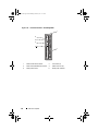
book.book Page 47 Wednesday, March 9, 2011 3:11 PM
Configuring the I/O Modules
3
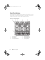
Overview
The M1000e enclosure supports three layers of I/O fabric. Each layer may
contain Ethernet, Infiniband, and Fibre Channel modules. Additional fabrics
may be supported in the future. You can install up to six hot-swappable I/O
modules in the enclosure, including Fibre Channel switches, Fibre-Channel
pass-throughs, Infiniband switches, Ethernet switches, and Ethernet passthrough modules. Figure 3-1 shows the numbering of the I/O bays and other
back-panel features.
Figure 3-1. I/O Module Bay Numbering
CMC 1
CMC 2
C2 B2 A2
iKVM
A1 B1 C1
1
2
3
4
5
6
7
8
9
1
2
3
4
5
6
Configuring the I/O Modules
47
book.book Page 48 Wednesday, March 9, 2011 3:11 PM
Fabric A
Fabric A is a redundant Gb Ethernet fabric, supporting I/O module slots A1
and A2. The integrated Ethernet controllers in each blade dictate Fabric A as
an Ethernet-only fabric.
NOTE: Fabric A supports KR (10 Gbps standard) if the midplane version in the
enclosure is 1.1 or later. To identify the midplane version, see "Identifying Midplane
Version" on page 49.
NOTE: Modules designed specifically for Fabric B or Fabric C cannot be installed in
slots A1 or A2, as indicated by the color-coded label on the faceplate of each module.
Fabric B
Fabric B is a 1 to 40 Gb/sec redundant fabric, supporting I/O module slots B1
and B2. Fabric B currently supports 1 Gb or 10 Gb Ethernet, DDR/QDR
Infiniband, and 4 Gbps or 8 Gbps Fibre Channel modules. Additional fabric
types may be supported in the future.
NOTE: Fabric B supports up to 16 Gbps Fibre Channel, Infiniband FDR (14 Gbps
standard), and KR (10 Gbps standard) if the midplane version in the enclosure is 1.1
or later. To identify the midplane version, see "Identifying Midplane Version" on
page 49.
To communicate with an I/O module in the Fabric B slots, a blade must have
a matching mezzanine card installed in a Fabric B mezzanine card location.
Modules designed for Fabric A may also be installed in the Fabric B slots.
Fabric C
Fabric C is a 1 to 40 Gb/sec redundant fabric, supporting I/O module slots C1
and C2. Fabric C currently supports 1 Gb or 10 Gb Ethernet, DDR/QDR
Infiniband, and 4 Gbps or 8 Gbps Fibre Channel modules. Additional fabric
types may be supported in the future.
NOTE: Fabric C supports up to 16 Gbps Fibre Channel, Infiniband FDR (14 Gbps
standard), and KR (10 Gbps standard) if the midplane version in the enclosure is 1.1
or later. To identify the midplane version, see "Identifying Midplane Version" on
page 49.
To communicate with an I/O module in the Fabric C slots, a blade must have
a matching mezzanine card installed in a Fabric C mezzanine card location.
Modules designed for Fabric A may also be installed in the Fabric C slots.
48
Configuring the I/O Modules
book.book Page 49 Wednesday, March 9, 2011 3:11 PM
For more information about I/O module installation guidelines, see your
Hardware Owner’s Manual.
Identifying Midplane Version
The version of the midplane installed in the enclosure is displayed in the
Midplane Revision field under the Summary tab of the CMC web-based
interface.
You can also view the icons at the back of the enclosure to identify the version
of the midplane. See Table 3-1.
Table 3-1. Identifying Midplane Version
Marking
Description
Midplane Version
I/O module slots A1, A2
1.1
I/O module slots B1, B2, C1,
1.1
I/O module slots A1, A2
1.0
I/O module slots B1, B2, C1,
1.0
and C2
and C2
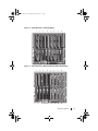
See Figure 3-2 and Figure 3-3 to locate the midplane identification labels on
the enclosure.
Configuring the I/O Modules
49
book.book Page 50 Wednesday, March 9, 2011 3:11 PM
Figure 3-2. Identifying Midplane Version 1.1
1
1
50
midplane identification labels (2)
Configuring the I/O Modules
book.book Page 51 Wednesday, March 9, 2011 3:11 PM
Figure 3-3. Identifying Midplane Version 1.0
1
1
midplane identification labels (2)
Configuring the I/O Modules
51
book.book Page 52 Wednesday, March 9, 2011 3:11 PM
Before You Begin
Network Information
You can configure your I/O switch modules using:
•
The CMC (see "Configuring a Switch Module Network Ethernet Port
Using the Web-Based Interface" on page 52).
•
The CMC CLI using serial console redirection.
•
Direct access to the I/O module’s serial port (if supported).
•
The I/O module’s default IP address (if supported).
NOTE: The default IP address for the CMC is 192.168.0.120.
Switch Modules
Configuring a Switch Module Network Ethernet Port Using the
Web-Based Interface
You can use the CMC Web-based interface to configure an I/O module’s
Ethernet port.
NOTE: Use this procedure to configure the switch’s out-of-band Ethernet port. The
switch’s in-band management IP address is configured through the switch’s
external ports. These two IP addresses must be different, and on different
networks.
NOTE: To change settings on the I/O module configuration page, you must have
Fabric Administrator privileges for the particular Fabric in which the module is
installed.
NOTE: The network IP address set on the I/O module by the CMC is not saved to a
configuration file. To save the IP address configuration permanently, use the
connect switch-n RACADM command, or use a direct interface to the I/O
module GUI.
NOTE: Do not attempt to configure I/O module network settings for Ethernet passthrough or Infiniband switches.
1 Log in to the CMC’s Web-based interface. See "Logging in to the CMC
Using the Web-Based Interface" on page 31.
2 Select I/O Modules in the Chassis menu in the system tree.
52
Configuring the I/O Modules
book.book Page 53 Wednesday, March 9, 2011 3:11 PM
3 Select the Setup tab. The Configuring I/O Modules Network Settings
page is displayed.
4 Configure the switch for integration into your network.
–
Select DHCP Mode Enabled if your network uses a DHCP server to
assign IP addresses.
–
If your network uses static IP addressing, enter an IP address, subnet
mask and gateway.
5 When you have finished, click Apply.
6 Click the Deploy sub-tab.
After all I/O modules have been configured and connected, the enclosure’s
blades can be inserted and booted with full network communication.
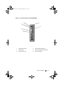
Dell PowerConnect-KR 8024-k Switch
The PowerConnect M8024-k switch provides 16 internal 10 GbE ports, four
external 10 GbE SFP+ ports, and one 10 GbE expansion slot for 10 GbE
external uplinks. The expansion slot on the front panel can support:
•
A 10 Gb Ethernet module with four optical SFP+ connectors
•
A 10 Gb Ethernet module with three copper CX4 uplinks
•
A 10 Gb Ethernet module with two copper 10GBASE-T uplinks
This module is hot-swappable and may be installed in Fabric A, B, or C.
Configuring the I/O Modules
53
book.book Page 54 Wednesday, March 9, 2011 3:11 PM
Figure 3-4. Dell PowerConnect-KR 8024-k Switch
5
1
2
4
54
3
1
SFP+ ports (4)
2
console management connector
3
status/identification indicator
4
power indicator
5
expansion slot
Configuring the I/O Modules
book.book Page 55 Wednesday, March 9, 2011 3:11 PM
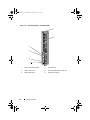
Dell M8428-k 10 Gb Converged Network Switch
The Dell M8428-k 10 Gb Converged Network switch module supports FCoE
protocols and allows Fibre Channel traffic to travel over 10 Gbps Enhanced
Ethernet (DCB) networks. This module consists of:
•
Four 8 Gbps external autosensing Fibre Channel ports.
•
Eight 10 Gb Enhanced Ethernet (DCB) optical SFP+ port connectors.
•
Sixteen internal 10 Gb Enhanced Ethernet (DCB/FCoE) ports that link to
the blades in the enclosure.
•
One serial port with an RJ-45 connector.
NOTE: This switch module includes Short Wave Small Form Factor Pluggable (SFP)
optical transceivers in the Fibre Channel ports. To ensure proper Fibre Channel
functionality, use only SFPs provided with this module.
This module can be installed in Fabric A, B, or C.
Configuring the I/O Modules
55
book.book Page 56 Wednesday, March 9, 2011 3:11 PM
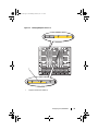
Figure 3-5. Dell M8428-k 10 Gb Converged Network Switch
1
7
2
6
3
5
56
4
1
LED status indicators (12)
2
serial port (RJ-45 connector)
3
module status indicator
4
status indicator
5
power indicator
6
8 Gb Fibre Channel ports
(ports 25–27 and port 0)
7
10 GbEE ports (ports 17–24)
Configuring the I/O Modules
book.book Page 57 Wednesday, March 9, 2011 3:11 PM
Mellanox M2401G DDR Infiniband Switch I/O Module
The Mellanox M2401G Infiniband switch I/O module includes 24 4x DDR
Infiniband ports. Eight ports are external uplink ports, while 16 internal ports
provide connectivity to the blades in the enclosure.
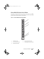
Figure 3-6. Mellanox M2401G Infiniband Switch Module
1
2
3
4
5
1
Infiniband ports (8)
2
port link status indicators (8)
3
port activity indicators (8)
4
module diagnostic power indicator
5
module status indicator
Configuring the I/O Modules
57
book.book Page 58 Wednesday, March 9, 2011 3:11 PM
Mellanox M3601Q QDR Infiniband Switch I/O Module
The Mellanox M3601 Infiniband switch I/O module includes 32 4x QDR
Infiniband ports. Of these, 16 ports are external uplink ports, while 16
internal ports provide connectivity to the blades in the enclosure. This
module occupies two I/O module slots. By default, the M3610Q module
plugs into I/O module slot C1, but occupies both slots B1 and C1. It can also
be plugged into I/O module slot B1 (occupying slots A1 and B1) or slot B2
(occupying slots B2 and C2).
58
Configuring the I/O Modules
book.book Page 59 Wednesday, March 9, 2011 3:11 PM
Figure 3-7. Mellanox M3601Q Infiniband Switch Module
1
2
3
4
5
1
Infiniband ports (16)
2
port link status indicators (16)
3
port activity indicators (16)
4
module diagnostic power indicator
5
module status indicator
Configuring the I/O Modules
59
book.book Page 60 Wednesday, March 9, 2011 3:11 PM
Cisco SFS M7000e Infiniband Switch I/O Module
The Cisco SFS M7000e Infiniband switch module includes 24 4x DDR
Infiniband ports. Eight ports are external uplink ports, and 16 internal ports
provide connectivity to the blades in the enclosure. This switch module is
hot-swappable, and may be installed in Fabric B or Fabric C.
Figure 3-8. Cisco SFS M7000e Infiniband Switch Module Features
1
2
3
4
60
1
Infiniband ports (8)
2
port status indicator (8)
3
diagnostic status indicator
4
power indicator
Configuring the I/O Modules
book.book Page 61 Wednesday, March 9, 2011 3:11 PM
Cisco Catalyst Ethernet Switch I/O Modules
Your system supports three Cisco Catalyst Blade Switch (CBS) versions:
•
The Cisco 3130G-S switch includes four 10/100/1000 Mb Ethernet uplink
ports and two Stackwise Plus ports.
•
The Cisco CBS 3130X-S switch includes four 10/100/1000 Mb Ethernet
uplink ports, two 10 Gb uplink ports, and two Stackwise Plus ports.
•
The Cisco CBS 3032 switch includes four 10/100/1000 Mb Ethernet
uplink ports.
The two option bays support the following module options:
•
Cisco X2 10 Gb transceiver modules (CBS 3130X-S only)
•
Cisco TwinGig converter modules
All three switches include an RJ-45 console connector for switch
management. Sixteen internal Gb Ethernet connectors link to the blades in
the enclosure.
For additional information about the Cisco CBS Ethernet switch modules,
see the documentation that shipped with the module.
Configuring the I/O Modules
61
book.book Page 62 Wednesday, March 9, 2011 3:11 PM
Figure 3-9. Cisco Catalyst Ethernet Switch Module Features
1
2
3
4
5
6
7
8
62
1
Stackwise Plus connectors (not
enabled in CBS 3032)
3
option bays (2)
4
Cisco status indicators
5
mode button
6
console port for switch
management
7
power indicator
8
status/identification indicator
Configuring the I/O Modules
2
10/100/1000 Mb Ethernet
connectors (4)
book.book Page 63 Wednesday, March 9, 2011 3:11 PM
PowerConnect M6220 Ethernet Switch I/O Module
The PowerConnect M6220 Ethernet switch module includes four external
10/100/1000 Mbps Ethernet connectors and one USB type A form factor serial
connector. Two option bays support the following modules:
•
A resilient stacking module with 2 x 24 Gb stacking ports
•
A 10 Gb Ethernet module with two 10 Gb optical XFP uplinks
•
A 10 Gb Ethernet module with two copper CX4 uplinks
•
A 10 Gb Ethernet module with two copper 10GBASE-T uplinks
•
A 10 Gb Ethernet module with two SFP+ (optical or direct-attach copper)
uplinks
Installing two optional modules provides additional stacking and redundancy
support. Sixteen internal Gb Ethernet connectors link to the blades in the
enclosure.
For additional information about the PowerConnect M6220 Ethernet switch
module, see the documentation that shipped with the module.
Configuring the I/O Modules
63
book.book Page 64 Wednesday, March 9, 2011 3:11 PM
Figure 3-10. PowerConnect M6220 Ethernet Switch Module Features
1
2
3
4
5
64
1
optional module (2) (dual 10 Gb
Ethernet uplink module shown)
2
standard 10/100/1000 Mb Ethernet
connectors (4)
3
serial connector (USB type-A form
factor)
4
power indicator
5
status/identification indicator
Configuring the I/O Modules
book.book Page 65 Wednesday, March 9, 2011 3:11 PM
PowerConnect M6348 1 Gb Ethernet Switch I/O Module
The PowerConnect M6348 is a hot-swappable 48-port 1 Gb Ethernet switch.
While 16 ports are external uplink ports, the remaining 32 internal ports
provide connectivity to the blades within the enclosure with a maximum
bandwidth of 1 Gbps each. The PowerConnect M6348 switch also supports:
•
Two integrated 10 Gb Ethernet SFP+ connectors
•
Two integrated CX4 connectors for stacking or 10 Gb uplinks
•
One console management connector
It is recommended that you use the PowerConnect M6348 switch with
quad-port mezzanine cards for maximum functionality. The quad-port
mezzanine cards and the PowerConnect M6348 Ethernet switch enable an
increased bandwidth (two 1 Gbps lanes), higher port density, and server
module consolidation.
Configuring the I/O Modules
65
book.book Page 66 Wednesday, March 9, 2011 3:11 PM
Figure 3-11. PowerConnect M6348 Switch Module
1
2
3
4
5
6
66
1
standard 10/100/1000 Mb
Ethernet connectors (16)
3
CX4 stacking connectors (2)
4
console management connector
5
power indicator
6
status/identification indicator
Configuring the I/O Modules
2
SFP+ connectors (2)
book.book Page 67 Wednesday, March 9, 2011 3:11 PM
PowerConnect M8024 10 Gb Ethernet Switch I/O Module
The PowerConnect M8024 switch module incorporates two optional bays
that support the following modules:
•
A 10 Gb Ethernet module with four optical SFP+ connectors
•
A 10 Gb Ethernet module with three copper CX4 uplinks
•
A 10 Gb Ethernet module with two copper 10GBASE-T uplinks
The modules can be used in any combination and are sold separately.
You can initially configure the switch using either of two methods:
•
Connect an external management system to the switch using an optional
USB type-A form factor serial cable, and configure the switch using a
terminal application.
•
Use the iKVM CMC console (“17th blade”) and the connect switch-n
CMC CLI command. For more information, see the CMC User’s Guide.
Once an IP address is assigned to the management VLAN or interface and the
switch is connected to a management network, both Telnet and http are
available through the network.
Configuring the I/O Modules
67
book.book Page 68 Wednesday, March 9, 2011 3:11 PM
Figure 3-12. PowerConnect M8024 Switch Module
1
2
3
4
5
68
1
optional module with four SFP+
ports
2
optional module with three CX4
ports
3
serial connector for optional USB
type-A form-factor cable
4
power indicator
5
status/identification indicator
Configuring the I/O Modules
book.book Page 69 Wednesday, March 9, 2011 3:11 PM
Brocade M4424 SAN I/O Module
The Brocade M4424 SAN I/O module includes eight external autosensing
Fibre Channel ports (four ports are enabled in the standard configuration and
four additional ports may be enabled as an optional upgrade), 16 internal
ports, and one serial port with an RJ-45 connector. The external Fibre
Channel ports operate at 1 Gb/sec, 2 Gb/sec, or 4 Gb/sec. The Fibre Channel
switch module is hot-swappable, and may be installed in Fabric B or Fabric C.
NOTE: The Fibre Channel switch module includes Short Wave Small Form Factor
Pluggable (SFP) optical transceivers. To ensure proper functionality, use only SFPs
provided with this module.
Configuring the I/O Modules
69
book.book Page 70 Wednesday, March 9, 2011 3:11 PM
Figure 3-13. Brocade M4424 SAN I/O Module
1
2
3
4
5
6
7
70
1
Fibre Channel port (8)
2
Fibre Channel port status
indicator (8)
3
Fibre Channel port speed
indicator (8)
4
serial port (RJ-45 connector)
5
module status indicator
6
power indicator
7
status/identification indicator
Configuring the I/O Modules
book.book Page 71 Wednesday, March 9, 2011 3:11 PM
Brocade M5424 FC8 I/O Module
The Brocade M5424 I/O module includes eight external autosensing Fibre
Channel ports (four ports are enabled in the standard configuration and four
additional ports may be enabled as an optional upgrade), 16 internal ports,
and one serial port with an RJ-45 connector. The external Fibre Channel ports
operate at 8 Gb/sec, 4 Gb/sec, or 2 Gb/sec.
NOTE: CMC firmware version 1.3 is required to support FC8 mezzanine cards and
I/O modules.
NOTE: This Fibre Channel switch module includes Short Wave Small Form Factor
Pluggable (SFP) optical transceivers. To ensure proper functionality, use only SFPs
provided with this module.
Configuring the I/O Modules
71
book.book Page 72 Wednesday, March 9, 2011 3:11 PM
Figure 3-14. Brocade M5424 FC8 I/O Module
1
2
3
4
5
6
7
72
1
Fibre Channel port (8)
2
Fibre Channel port status
indicator (8)
3
Fibre Channel port speed
indicator (8)
4
serial port (RJ-45 connector)
5
module status indicator
6
power indicator
7
status/identification indicator
Configuring the I/O Modules
book.book Page 73 Wednesday, March 9, 2011 3:11 PM
Dell 8/4 Gbps FC SAN Module
The Dell 8/4 Gbps FC SAN module (see Figure 3-15) includes 24 total
autosensing Fibre Channel ports (12 ports are enabled in the standard
configuration and 12 additional ports may be enabled as an optional upgrade)
and one serial port with an RJ-45 connector. The internal Fibre Channel ports
operate at 8 Gb/sec or 4 Gb/sec. The external Fibre Channel ports operate at
8 Gb/sec, 4 Gb/sec, or 2 Gb/sec.
NOTE: CMC firmware version 1.3 is required to support FC8 mezzanine cards and
I/O modules.
NOTE: This Fibre Channel switch module includes Short Wave Small Form Factor
Pluggable (SFP) optical transceivers. To ensure proper functionality, use only SFPs
provided with this module.
Configuring the I/O Modules
73
book.book Page 74 Wednesday, March 9, 2011 3:11 PM
Figure 3-15. Dell 8/4 Gbps FC SAN Module
1
2
3
4
5
6
7
74
1
Fibre Channel port (8)
2
Fibre Channel port status
indicator (8)
3
Fibre Channel port speed
indicator (8)
4
serial port (RJ-45 connector)
5
module status indicator
6
power indicator
7
status/identification indicator
Configuring the I/O Modules
book.book Page 75 Wednesday, March 9, 2011 3:11 PM
Pass-Through Modules
Dell 10 GbE KR Pass-Through I/O Module
The 10 GbE KR pass-through module supports 10 Gb connections and
provides a direct connection between the optional internal Ethernet KR
mezzanine card or KR network daughter card in the blade and an external
Ethernet device. This module has 16 external SFP+ ports on the front panel
and sixteen 10 GbE KR internal ports through the backplane. This module
enables you to use optical SFP+ (short reach or long reach) and direct-attached
copper (DCA) SFP+ modules.
The Ethernet pass-through module is hot-swappable and may be installed in
Fabric A, B, or C. The pass-through module does not support 1G mezzanine
or network daughter cards in blades.
Configuring the I/O Modules
75
book.book Page 76 Wednesday, March 9, 2011 3:11 PM
Figure 3-16. Dell 10 GbE KR Pass-Through I/O Module
1
2
4
76
3
1
SFP+ ports (16)
2
green/amber indicators (two per
port)
3
status/identification indicator
4
power indicator
Configuring the I/O Modules
book.book Page 77 Wednesday, March 9, 2011 3:11 PM
Dell 8/4 Gbps Fibre Channel Pass-Through I/O Module
The 8G Fibre Channel pass-through module provides a bypass connection
between a Fibre Channel mezzanine card in the blade and optical
transceivers. The bypass connection enables a direct connection to a Fibre
Channel switch or a storage array. The 16 pass-through ports on this module
can negotiate speeds of 2, 4, and 8 Gbps. The 8G Fibre Channel pass-through
module is hot-swappable and may be installed in Fabric B or Fabric C.
NOTE: To ensure proper functionality, use only the Short Wave Small Form Factor
Pluggable (SFP) transceivers provided with this module.
Configuring the I/O Modules
77
book.book Page 78 Wednesday, March 9, 2011 3:11 PM
Figure 3-17. Dell 8/4 Gbps Fibre Channel Pass-Through I/O Module
1
2
4
78
3
1
Fibre Channel ports (16)
2
port status indicators
3
status/identification indicator
4
power indicator
Configuring the I/O Modules
book.book Page 79 Wednesday, March 9, 2011 3:11 PM
10 Gb Ethernet Pass-Through Module II
The Dell 10 Gb Ethernet pass-through module II supports 10 Gb connections
and provides a direct connection between the optional internal Ethernet
mezzanine card in the blade and an external Ethernet device. The Ethernet
pass-through modules are hot-swappable and may be installed in Fabric B or
Fabric C.
The 10 Gb Ethernet pass-through module II enables you to use optical SFP+
(short reach or long reach) and direct-attached copper (DCA) SFP+
modules. The Ethernet pass-through module does not support 1G mezzanine
or network daughter cards in blades.
Configuring the I/O Modules
79
book.book Page 80 Wednesday, March 9, 2011 3:11 PM
Figure 3-18. 10 Gb Ethernet Pass-Through Module II
1
2
3
4
80
1
SFP+ cages (16)
2
green/amber indicators (two per
port)
3
status/identification indicator
4
power indicator
Configuring the I/O Modules
book.book Page 81 Wednesday, March 9, 2011 3:11 PM
10 Gb Ethernet Pass-Through I/O Module
The 10 Gb Ethernet pass-through module supports 10 Gb connections
and provides a direct connection between the optional internal Ethernet
mezzanine card in the blade and an external Ethernet device. The Ethernet
pass-through modules are hot-swappable and may be installed in Fabric B or
Fabric C.
The 10 Gb Ethernet pass-through I/O module enables you to use optical SFP,
SFP+, and direct-attached copper (DCA) SFP+ modules. To operate the I/O
module and the SFP+ modules at 10 Gbps, you must use either optical SFP+
short reach (SR), long reach multimode (LRM), or DCA SFP+ modules. This
module does not support 1G mezzanine or network daughter cards in blades.
Configuring the I/O Modules
81
book.book Page 82 Wednesday, March 9, 2011 3:11 PM
Figure 3-19. 10 Gb Ethernet Pass-Through I/O Module
1
2
3
4
82
1
SFP+ cages (16)
2
green/amber indicators (two per
port)
3
power indicator
4
status/identification indicator
Configuring the I/O Modules
book.book Page 83 Wednesday, March 9, 2011 3:11 PM
10/100/1000 Mb Ethernet Pass-Through I/O Module
The Ethernet pass-through module supports 10/100/1000 Mb connections
and provides a direct connection between the optional internal Ethernet
mezzanine card in the blade and an external Ethernet device. The Ethernet
pass-through modules are hot-swappable and may be installed in any of the
three Fabrics.
Configuring the I/O Modules
83
book.book Page 84 Wednesday, March 9, 2011 3:11 PM
Figure 3-20. Ethernet Pass-Through Module
1
2
5
3
4
1
link indicator (16)
2
RJ45 Ethernet connector (16)
3
power indicator
4
status/identification indicator
5
activity indicator (16)
NOTE: Connectors on the Ethernet pass-through module correspond directly to the
blade number. For example, blade 5 is connected to port 5 on the Ethernet passthrough module. Integrated network adapter 1 maps to I/O slot A1. Integrated
network adapter 2 maps to I/O slot A2.
84
Configuring the I/O Modules
book.book Page 85 Wednesday, March 9, 2011 3:11 PM
4G Fibre Channel Pass-Through I/O Module
The 4G Fibre Channel pass-through module provides a bypass connection
between a Fibre Channel mezzanine card in the blade and optical transceivers.
The bypass connection enables a direct connection to a Fibre Channel switch
or a storage array. The 16 pass-through ports on this module can negotiate
speeds of 1, 2, or 4 Gbps. The 4G Fibre Channel pass-through module is
hot-swappable, and may be installed in Fabric B or Fabric C.
NOTE: To ensure proper functionality, use only the Short Wave Small Form Factor
Pluggable (SFP) transceivers provided with this module.
Configuring the I/O Modules
85
book.book Page 86 Wednesday, March 9, 2011 3:11 PM
Figure 3-21. 4G Fibre Channel Pass-Through Module
1
2
3
4
86
1
SFP Fibre Channel connector (16)
2
Fibre Channel green/amber
indicators (two per port)
3
power indicator
4
status/identification indicator
Configuring the I/O Modules