1
Spine page range - 145 to 208 — Rev. 9/9/98
Printer!!! - Black Plate Prints Black
Printer!!! - Magenta Plate Prints PMS 375
Printer!!! - Cyan Plate Prints PMS 3005
®
3ULQWHGLQWKH86$
'HOO ,QVSLURQ3RUWDEOH&RPSXWHU
'HOO ,QVSLURQ 3RUWDEOH &RPSXWHU
5HIHUHQFH DQG 7URXEOHVKRRWLQJ *XLGH
®
5()(5(1&($1'
7528%/(6+227,1*
*8,'(
ZZZGHOOFRP
Printer!!! - Black Plate Prints Black
Printer!!! - Magenta Plate Prints PMS 375
Printer!!! - Cyan Plate Prints PMS 3005
31'
ZZZGHOOFRP
0RGHO 767
®
'HOO ,QVSLURQ3RUWDEOH&RPSXWHU
5()(5(1&($1'
7528%/(6+227,1*
*8,'(
ZZZGHOOFRP
_____________________
Information in this document is subject to change without notice.
© 1998 Dell Computer Corporation. All rights reserved.
Reproduction in any manner whatsoever without the written permission of Dell Computer Corporation is strictly forbidden.
Trademarks used in this text: Dell, the DELL logo, Optiplex, and Dell Dimension are registered trademarks, DellWare is a registered
service mark, and Inspiron is a trademark of Dell Computer Corporation; Microsoft, MS-DOS, and Windows are registered trademarks
of Microsoft Corporation; Intel and Pentium are registered trademarks and MMX is a trademark of Intel Corporation; Iomega is a
registered trademark of Iomega Corporation.
Other trademarks and trade names may be used in this document to refer to either the entities claiming the marks and names or their
products. Dell Computer Corporation disclaims any proprietary interest in trademarks and trade names other than its own.
September 1998
P/N 2233D
6DIHW\,QVWUXFWLRQV
Use the following safety guidelines to help protect your computer from potential damage and to help ensure your own personal safety.
:KHQ8VLQJ<RXU&RPSXWHU
As you use your computer, observe the following safety guidelines:
Do not attempt to service the computer yourself. Always follow installation
instructions closely.
Do not carry a battery pack in your pocket, purse, or other container where metal
objects (such as car keys) could short-circuit the battery terminals. The resulting
excessive current flow can cause extremely high temperatures and may result in
damage from burns.
Be sure that nothing rests on your AC adapter’s power cable and that the cable is
not located where it can be tripped over or stepped on.
Do not use your computer in a wet environment, for example, near a bathtub,
sink, or swimming pool or in a wet basement.
Use only the AC adapter and batteries that are approved for use with this computer as indicated in this document.
If your computer includes an onboard or optional modem, disconnect the modem
cable during an electrical storm to avoid the remote risk of electric shock from
lightning.
Do not dispose of battery packs in a fire. They may explode. Check with local
authorities for disposal instructions.
Before you clean your computer, turn it off, unplug it from its power source, and
remove the battery pack(s).
When setting up the computer for work, place it on a level surface.
When traveling, do not check the computer as baggage. You can put your computer through an X-ray security machine, but never put your computer through a
metal detector. If you have the computer checked by hand, be sure to have a
charged battery available in case you are asked to turn on the computer.
v
When traveling with the hard-disk drive removed from the computer, wrap the
drive in a nonconducting material, such as cloth or paper. If you have the drive
checked by hand, be ready to install the drive in the computer. You can put the
hard-disk drive through an X-ray security machine, but never put the drive through
a metal detector.
When traveling, do not place the computer in overhead storage compartments
where it could slide around. Do not drop your computer or subject it to other
mechanical shocks.
Protect your computer, battery, and hard-disk drive from environmental hazards
such as dirt, dust, food, liquids, temperature extremes, and overexposure to
sunlight.
When you move your computer between environments with very different temperature and/or humidity ranges, condensation may form on or within the
computer. To avoid damaging the computer, allow sufficient time for the moisture
to evaporate before using the computer.
&$87,21 :KHQ WDNLQJ WKH FRPSXWHU IURP ORZWHPSHUDWXUH FRQGLWLRQV
LQWR D ZDUPHU HQYLURQPHQW RU IURP KLJKWHPSHUDWXUH FRQGLWLRQV LQWR D
FRROHU HQYLURQPHQW DOORZ WKH FRPSXWHU WR DFFOLPDWH WR URRP WHPSHUD
WXUH EHIRUH WXUQLQJ RQ SRZHU
vi
When you disconnect a cable, pull on its connector or on its strain-relief loop, not
on the cable itself. As you pull out the connector, keep it evenly aligned to avoid
bending any connector pins. Also, before you connect a cable make sure both
connectors are correctly oriented and aligned.
Handle components with care. Hold a component such as a memory module by
its edges, not its pins.
When removing a memory module from the system board or disconnecting a
peripheral device from the computer, wait 5 seconds after turning off the computer before removing the memory module or disconnecting the device to help
avoid possible damage to the system board.
Clean your computer with a soft cloth dampened with water rather than with
liquid or aerosol cleaners.
Clean the display with a soft, clean cloth and commercial window cleaner that
does not contain wax or abrasives. Apply the cleaner to the cloth; then stroke the
cloth across the display in one direction, moving from the top of the display to the
bottom. If the display contains grease or some other contaminant, use isopropyl
alcohol instead of commercial window cleaner.
If your computer gets wet or is damaged, follow the procedures described in
Chapter 3, “Troubleshooting Your Computer.” If, after following these procedures, you confirm that your computer is not operating properly, contact Dell
Computer Corporation. (See Chapter 5, “Getting Help,” for the appropriate telephone number.)
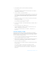
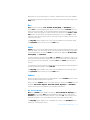
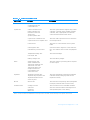
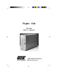
(UJRQRPLF&RPSXWLQJ+DELWV
:$51,1* ,PSURSHU RU SURORQJHG NH\ERDUG XVH PD\ UHVXOW LQ LQMXU\
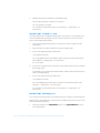
For comfort and efficiency, observe the following ergonomic guidelines when setting
up and using your computer:
Position your computer directly in front of you as you work.
Adjust the tilt of the computer’s display, its contrast and/or brightness settings,
and the lighting around you (such as overhead lights, desk lamps, and the curtains or blinds on nearby windows) to minimize reflections and glare on the
display.
When using an external monitor with your computer, set the monitor at a comfortable viewing distance (usually 510 to 610 millimeters [20 to 24 inches] from
your eyes). Make sure the monitor screen is at eye level or slightly lower when
you are sitting in front of the monitor.
Use a chair that provides good lower-back support.
Keep your forearms horizontal with your wrists in a neutral, comfortable position
while using the keyboard, trackball, touch pad, or external mouse.
Always use the palmrest with the keyboard, touch pad, or trackball. Leave space
to rest your hands when using an external mouse.
Let your upper arms hang naturally at your sides.
Sit erect with your feet resting on the floor and your thighs level.
When sitting, make sure the weight of your legs is on your feet and not on the
front of your chair seat. Adjust your chair’s height or use a footrest, if necessary,
to maintain proper posture.
Vary your work activities. Try to organize your work so that you do not have to
type for extended periods of time. When you stop typing, try to do things that
use both hands.
vii
computer positioned
directly in front
of user
wrists relaxed
and flat
arms at desk level
:KHQ5HPRYLQJRU,QVWDOOLQJ0HPRU\
0RGXOHV
Before removing or installing memory modules, perform the following steps in the
sequence indicated.
&$87,21 7KH RQO\ WLPH \RX VKRXOG HYHU DFFHVV WKH LQVLGH RI \RXU FRPSXWHU
LV ZKHQ \RX DUH LQVWDOOLQJ PHPRU\ PRGXOHV
&$87,21 :DLW VHFRQGV DIWHU WXUQLQJ RII WKH FRPSXWHU EHIRUH GLVFRQQHFW
LQJ D SHULSKHUDO GHYLFH RU UHPRYLQJ D PHPRU\ PRGXOH WR KHOS SUHYHQW
SRVVLEOH GDPDJH WR WKH V\VWHP ERDUG
1.
Turn off your computer and any attached peripherals.
2.
Disconnect your computer and peripherals from AC power to reduce the potential for personal injury or shock. Also, disconnect any telephone or
telecommunication lines from the computer.
3.
Remove the main battery from the battery compartment and, if necessary, the
secondary battery from the options bay.
4.
Ground yourself by touching the unpainted metal surface of the input/output (I/O)
panel on the back of the computer.
While you work, periodically touch the I/O panel to dissipate any static electricity
that might harm internal components.
viii
3URWHFWLQJ$JDLQVW(OHFWURVWDWLF'LVFKDUJH
Static electricity can harm electronic components inside your computer. To prevent
static damage, discharge static electricity from your body before you touch any of
your computer’s electronic components, such as a memory module. You can do so by
touching an unpainted metal surface on the computer’s I/O panel.
As you continue to work inside the computer, periodically touch an I/O connector to
remove any static charge your body may have accumulated.
You can also take the following steps to prevent damage from electrostatic discharge
(ESD):
When unpacking a static-sensitive component from its shipping carton, do not
remove the component from the antistatic packing material until you are ready to
install the component. Just before unwrapping the antistatic packaging, be sure
to discharge static electricity from your body.
When transporting a sensitive component, first place it in an antistatic container
or packaging.
Handle all sensitive components in a static-safe area. If possible, use antistatic
floor pads and workbench pads.
The following caution may appear throughout this document to remind you of these
precautions:
&$87,21 6HH ´3URWHFWLQJ $JDLQVW (OHFWURVWDWLF 'LVFKDUJHµ LQ WKH VDIHW\
LQVWUXFWLRQV DW WKH IURQW RI WKLV JXLGH
ix
x
3UHIDFH
$ERXW7KLV*XLGH
This guide is intended for anyone who uses the Dell Inspiron 3500 portable computer.
It can be used by both first-time and experienced computer users who want to learn
about the features of the computer. This guide also provides basic troubleshooting
procedures and instructions for using the Dell Diagnostics to test your computer and
its components.
Summaries of the chapters and appendixes of this guide follow:
Read Chapter 1, “Introduction,” for an overview of the computer features and a
list of available upgrades.
Read Chapter 2, “Customizing System Features,” to learn how to access the
Setup program, which allows you to change system settings, such as your computer’s power conservation features.
Read Chapter 3, “Troubleshooting Your Computer,” for some initial checks and
procedures that can be used to solve basic computer problems and for some
general guidelines on analyzing software problems. This chapter also discusses
messages and beep codes.
Read Chapter 4, “Running the Dell Diagnostics,” for hardware-related problems.
The Dell Diagnostics checks your computer’s hardware and isolates component
problems.
Chapter 5, “Getting Help,” describes the help tools Dell provides to assist you if
you have a problem with the computer. It also explains how and when to call Dell
for technical assistance.
Appendix A, “Technical Specifications,” is intended primarily as reference material if you are interested in learning more about the details of your computer.
Appendix B, “Diagnostic Video Tests,” provides samples of screens displayed
when you run the Video Test Group of the Dell Diagnostics. These screens help
you check a particular video function or group of functions on the built-in display
or on an external monitor.
xi
Appendix C, “Regulatory Notices,” is for users who are interested in which regulatory agencies have tested and approved the Dell Inspiron 3500 portable
computer.
Appendix D, “Warranty, Return Policy, and Year 2000 Statement of Compliance,”
describes the warranty and return policy for your Dell computer.
:DUUDQW\DQG5HWXUQ3ROLF\,QIRUPDWLRQ
Dell Computer Corporation (“Dell”) manufactures its hardware products from parts
and components that are new or equivalent to new in accordance with industry-standard practices.
For information about the Dell warranty and return policy, see Appendix D, “Warranty,
Return Policy, and Year 2000 Statement of Compliance.”
2WKHU'RFXPHQWV<RX0D\1HHG
Besides this Reference and Troubleshooting Guide, the following online documentation
is included with your computer:
The Windows-based System User’s Guide contains essential information
you need to use your portable computer. Look for the Online Guide icon on
the desktop.
The Dell Service and Support Policies provides information about service
and support policies, guarantees, and warranties (in the United States only).
Look for the Dell Services and Support Policies icon in the Dell Accessories folder.
You may also have one or more of the following documents.
NOTE: Documentation updates are sometimes included with your computer to
describe changes to your computer or software. Always read these updates before
consulting any other documentation because the updates contain the latest information.
xii
The Dell-Installed Microsoft Windows 98 Setup Guide, which describes how to
set up the Microsoft Windows 98 operating system on your Dell computer.
Microsoft Windows 98 operating system documentation is included if you
ordered your operating system from Dell. This documentation describes how to
configure and use your operating system software.
Documentation is included with any options you purchase separately from your
computer. This documentation includes information that you need to configure
and install these options in your Dell computer.
“Readme” files may be installed on your hard-disk drive to provide last-minute
updates about technical changes to your computer or advanced technical reference material intended for experienced users or technicians.
1RWDWLRQDO&RQYHQWLRQV
The following subsections list notational conventions used in this document.
1RWHV&DXWLRQVDQG:DUQLQJV
Throughout this guide, blocks of text may be accompanied by an icon and printed in
bold type or in italic type. These blocks are notes, cautions, and warnings, and they
are used as follows:
NOTE: A NOTE indicates important information that helps you make better use of
your computer.
&$87,21 $ &$87,21 LQGLFDWHV HLWKHU SRWHQWLDO GDPDJH WR KDUGZDUH RU
ORVV RI GDWD DQG WHOOV \RX KRZ WR DYRLG WKH SUREOHP
:$51,1* $ :$51,1* LQGLFDWHV WKH SRWHQWLDO IRU ERGLO\ KDUP DQG WHOOV
\RX KRZ WR DYRLG WKH SUREOHP
Some warnings may appear in alternate formats and may be unaccompanied by an
icon. In such cases, the specific presentation of the warning is mandated by regulatory authority.
7\SRJUDSKLFDO&RQYHQWLRQV
The following list defines (where appropriate) and illustrates typographical conventions used as visual cues for specific elements of text throughout this document:
Interface components are window titles, button and icon names, menu names
and selections, and other options that appear on the monitor screen or display.
They are presented in bold.
Example: Click OK.
Keycaps, the labeling that appears on the keys on a keyboard, are enclosed in
angle brackets.
Example: <Enter>
Key combinations are series of keys to be pressed simultaneously (unless otherwise indicated) to perform a single function.
Example: <Ctrl><Alt><Enter>
Commands presented in lowercase bold are for reference purposes only and are
not intended to be typed at that particular point in the discussion.
Example: “Use the setup command to . . . .”
In contrast, commands presented in the Courier New font are intended to be
typed as part of an instruction.
Example: “Type format to format the diskette in drive A.”
xiii
Filenames and directory names are presented in lowercase bold.
Examples: autoexec.bat and c:\windows
Syntax lines consist of a command and all its possible parameters. Commands
are displayed in lowercase bold; variable parameters (those for which you substitute a value) are displayed in lowercase italics; constant parameters are displayed
in lowercase bold. The brackets indicate items that are optional.
Example: del [drive:] [[path]filename] [/p]
Command lines consist of a command and may include one or more of the command’s possible parameters. Command lines are presented in the Courier New
font.
Example: del c:\myfile.doc
Screen text is text that appears on the screen of your display or external monitor.
It can be a system message, for example, or it can be text that you are instructed
to type as part of a command (referred to as a command line). Screen text is presented in the Courier New font.
Example: The following message appears on your screen:
No boot device available
Variables are symbols for which you substitute a value. They are presented in
italics.
Example: module n (where n represents the memory module number)
xiv
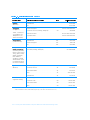
&RQWHQWV
&KDSWHU
,QWURGXFWLRQ Hardware Features . . . . . . . . . . . . . . . . . . . . . . . . . . . . . . . . . . . . . . . . . . . . . . . . . 1-3
Software Features . . . . . . . . . . . . . . . . . . . . . . . . . . . . . . . . . . . . . . . . . . . . . . . . . . 1-5
Using the Power Button . . . . . . . . . . . . . . . . . . . . . . . . . . . . . . . . . . . . . . . . . . . . . 1-5
Accessing Electronic Documentation . . . . . . . . . . . . . . . . . . . . . . . . . . . . . . . . . . . 1-6
Available Options. . . . . . . . . . . . . . . . . . . . . . . . . . . . . . . . . . . . . . . . . . . . . . . . . . . 1-6
Getting Help . . . . . . . . . . . . . . . . . . . . . . . . . . . . . . . . . . . . . . . . . . . . . . . . . . . . . . 1-7
&KDSWHU
&XVWRPL]LQJ6\VWHP)HDWXUHV System Utilities . . . . . . . . . . . . . . . . . . . . . . . . . . . . . . . . . . . . . . . . . . . . . . . . . . . . 2-1
Setup Program. . . . . . . . . . . . . . . . . . . . . . . . . . . . . . . . . . . . . . . . . . . . . . . . . . . . . 2-2
Accessing the Setup Program . . . . . . . . . . . . . . . . . . . . . . . . . . . . . . . . . . . . . 2-3
Main Menu Options . . . . . . . . . . . . . . . . . . . . . . . . . . . . . . . . . . . . . . . . . . . . . 2-3
System Time . . . . . . . . . . . . . . . . . . . . . . . . . . . . . . . . . . . . . . . . . . . . . . . 2-4
System Date . . . . . . . . . . . . . . . . . . . . . . . . . . . . . . . . . . . . . . . . . . . . . . . 2-4
Floppy Drive . . . . . . . . . . . . . . . . . . . . . . . . . . . . . . . . . . . . . . . . . . . . . . . 2-4
Hard Disk. . . . . . . . . . . . . . . . . . . . . . . . . . . . . . . . . . . . . . . . . . . . . . . . . . 2-4
Quiet Boot. . . . . . . . . . . . . . . . . . . . . . . . . . . . . . . . . . . . . . . . . . . . . . . . . 2-4
Video Display Device. . . . . . . . . . . . . . . . . . . . . . . . . . . . . . . . . . . . . . . . . 2-4
System Memory . . . . . . . . . . . . . . . . . . . . . . . . . . . . . . . . . . . . . . . . . . . . 2-4
Extended Memory . . . . . . . . . . . . . . . . . . . . . . . . . . . . . . . . . . . . . . . . . . 2-5
System Devices Menu Options . . . . . . . . . . . . . . . . . . . . . . . . . . . . . . . . . . . . 2-5
IDE Controller . . . . . . . . . . . . . . . . . . . . . . . . . . . . . . . . . . . . . . . . . . . . . . 2-5
FDD Controller . . . . . . . . . . . . . . . . . . . . . . . . . . . . . . . . . . . . . . . . . . . . . 2-6
Serial Port . . . . . . . . . . . . . . . . . . . . . . . . . . . . . . . . . . . . . . . . . . . . . . . . . 2-6
Infrared Port . . . . . . . . . . . . . . . . . . . . . . . . . . . . . . . . . . . . . . . . . . . . . . . 2-6
Parallel Port . . . . . . . . . . . . . . . . . . . . . . . . . . . . . . . . . . . . . . . . . . . . . . . . 2-6
Modem Port . . . . . . . . . . . . . . . . . . . . . . . . . . . . . . . . . . . . . . . . . . . . . . . 2-7
Audio . . . . . . . . . . . . . . . . . . . . . . . . . . . . . . . . . . . . . . . . . . . . . . . . . . . . . 2-7
xv
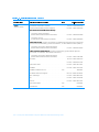
Security Menu Options . . . . . . . . . . . . . . . . . . . . . . . . . . . . . . . . . . . . . . . . . . 2-7
System Password is . . . . . . . . . . . . . . . . . . . . . . . . . . . . . . . . . . . . . . . . . 2-8
Set System Password . . . . . . . . . . . . . . . . . . . . . . . . . . . . . . . . . . . . . . . 2-8
Password On Boot . . . . . . . . . . . . . . . . . . . . . . . . . . . . . . . . . . . . . . . . . . 2-8
Power Menu Options. . . . . . . . . . . . . . . . . . . . . . . . . . . . . . . . . . . . . . . . . . . . 2-8
Power Management Mode. . . . . . . . . . . . . . . . . . . . . . . . . . . . . . . . . . . . 2-9
CPU Throttling . . . . . . . . . . . . . . . . . . . . . . . . . . . . . . . . . . . . . . . . . . . . . 2-9
Standby Time-Out. . . . . . . . . . . . . . . . . . . . . . . . . . . . . . . . . . . . . . . . . . 2-10
Suspend Time-Out . . . . . . . . . . . . . . . . . . . . . . . . . . . . . . . . . . . . . . . . . 2-10
Suspend Mode . . . . . . . . . . . . . . . . . . . . . . . . . . . . . . . . . . . . . . . . . . . . 2-11
Resume On Modem Ring. . . . . . . . . . . . . . . . . . . . . . . . . . . . . . . . . . . . 2-11
Resume On Time of Day . . . . . . . . . . . . . . . . . . . . . . . . . . . . . . . . . . . . 2-11
Resume Time . . . . . . . . . . . . . . . . . . . . . . . . . . . . . . . . . . . . . . . . . . . . . 2-11
Boot Menu Options . . . . . . . . . . . . . . . . . . . . . . . . . . . . . . . . . . . . . . . . . . . . 2-12
Exit Menu Options . . . . . . . . . . . . . . . . . . . . . . . . . . . . . . . . . . . . . . . . . . . . . 2-13
Save Changes and Exit . . . . . . . . . . . . . . . . . . . . . . . . . . . . . . . . . . . . . . 2-13
Discard Changes and Exit . . . . . . . . . . . . . . . . . . . . . . . . . . . . . . . . . . . . 2-13
Load Factory Defaults. . . . . . . . . . . . . . . . . . . . . . . . . . . . . . . . . . . . . . . 2-14
Load Last Saved Values . . . . . . . . . . . . . . . . . . . . . . . . . . . . . . . . . . . . . 2-14
Save Changes . . . . . . . . . . . . . . . . . . . . . . . . . . . . . . . . . . . . . . . . . . . . . 2-14
Creating the Save-to-Disk Suspend File . . . . . . . . . . . . . . . . . . . . . . . . . . . . . . . . 2-14
Reinstalling the System User’s Guide. . . . . . . . . . . . . . . . . . . . . . . . . . . . . . . . . . 2-15
&KDSWHU
7URXEOHVKRRWLQJ<RXU&RPSXWHU Backing Up Your Files . . . . . . . . . . . . . . . . . . . . . . . . . . . . . . . . . . . . . . . . . . . . . . . 3-1
Basic Checks. . . . . . . . . . . . . . . . . . . . . . . . . . . . . . . . . . . . . . . . . . . . . . . . . . . . . . 3-2
Checking Connections . . . . . . . . . . . . . . . . . . . . . . . . . . . . . . . . . . . . . . . . . . . 3-3
Look and Listen . . . . . . . . . . . . . . . . . . . . . . . . . . . . . . . . . . . . . . . . . . . . . . . . . . . 3-6
Setup Options . . . . . . . . . . . . . . . . . . . . . . . . . . . . . . . . . . . . . . . . . . . . . . . . . 3-7
Messages and Codes . . . . . . . . . . . . . . . . . . . . . . . . . . . . . . . . . . . . . . . . . . . . . . . 3-7
System Beep Codes . . . . . . . . . . . . . . . . . . . . . . . . . . . . . . . . . . . . . . . . . . . . 3-9
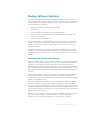
Finding Software Solutions . . . . . . . . . . . . . . . . . . . . . . . . . . . . . . . . . . . . . . . . . . 3-11
Installing and Configuring Software . . . . . . . . . . . . . . . . . . . . . . . . . . . . . . . . 3-11
Start-Up Files . . . . . . . . . . . . . . . . . . . . . . . . . . . . . . . . . . . . . . . . . . . . . 3-12
Using Software . . . . . . . . . . . . . . . . . . . . . . . . . . . . . . . . . . . . . . . . . . . . . . . 3-12
Error Messages . . . . . . . . . . . . . . . . . . . . . . . . . . . . . . . . . . . . . . . . . . . 3-12
Input Errors . . . . . . . . . . . . . . . . . . . . . . . . . . . . . . . . . . . . . . . . . . . . . . . 3-12
Memory-Resident Programs. . . . . . . . . . . . . . . . . . . . . . . . . . . . . . . . . . 3-12
Program Conflicts . . . . . . . . . . . . . . . . . . . . . . . . . . . . . . . . . . . . . . . . . . 3-13
Avoiding Interrupt Assignment Conflicts . . . . . . . . . . . . . . . . . . . . . . . . 3-13
xvi
Troubleshooting Procedures . . . . . . . . . . . . . . . . . . . . . . . . . . . . . . . . . . . . . . . . .
Troubleshooting a Wet Computer . . . . . . . . . . . . . . . . . . . . . . . . . . . . . . . . .
Troubleshooting a Damaged Computer . . . . . . . . . . . . . . . . . . . . . . . . . . . . .
Troubleshooting a Power Failure . . . . . . . . . . . . . . . . . . . . . . . . . . . . . . . . . .
Total Power Failure When Using the AC Adapter . . . . . . . . . . . . . . . . . .
Total Power Failure When Using a Battery . . . . . . . . . . . . . . . . . . . . . . .
No Power to a Part of the Computer . . . . . . . . . . . . . . . . . . . . . . . . . . .
Troubleshooting the Diskette Drive . . . . . . . . . . . . . . . . . . . . . . . . . . . . . . . .
Troubleshooting the CD-ROM or DVD-ROM Drive . . . . . . . . . . . . . . . . . . . .
Troubleshooting the Hard-Disk Drive . . . . . . . . . . . . . . . . . . . . . . . . . . . . . . .
Troubleshooting an External Keyboard. . . . . . . . . . . . . . . . . . . . . . . . . . . . . .
Troubleshooting Memory . . . . . . . . . . . . . . . . . . . . . . . . . . . . . . . . . . . . . . . .
Troubleshooting the Display. . . . . . . . . . . . . . . . . . . . . . . . . . . . . . . . . . . . . .
Troubleshooting an External Monitor . . . . . . . . . . . . . . . . . . . . . . . . . . . . . . .
Troubleshooting the Serial and Parallel Ports . . . . . . . . . . . . . . . . . . . . . . . . .
Troubleshooting the Basic I/O Functions . . . . . . . . . . . . . . . . . . . . . . . .
Troubleshooting a Parallel Printer . . . . . . . . . . . . . . . . . . . . . . . . . . . . . .
Troubleshooting a Serial I/O Device . . . . . . . . . . . . . . . . . . . . . . . . . . . .
Troubleshooting the Infrared Port . . . . . . . . . . . . . . . . . . . . . . . . . . . . . .
Troubleshooting the Touch Pad . . . . . . . . . . . . . . . . . . . . . . . . . . . . . . . . . . .
Troubleshooting Audio Functions. . . . . . . . . . . . . . . . . . . . . . . . . . . . . . . . . .
&KDSWHU
3-14
3-14
3-17
3-18
3-19
3-20
3-21
3-22
3-23
3-24
3-25
3-27
3-29
3-30
3-31
3-32
3-33
3-34
3-34
3-35
3-36
5XQQLQJWKH'HOO'LDJQRVWLFV Features of the Dell Diagnostics . . . . . . . . . . . . . . . . . . . . . . . . . . . . . . . . . . . . . . .
When to Use the Dell Diagnostics . . . . . . . . . . . . . . . . . . . . . . . . . . . . . . . . . . . . .
Before You Start Testing . . . . . . . . . . . . . . . . . . . . . . . . . . . . . . . . . . . . . . . . . . . . .
Starting the Dell Diagnostics . . . . . . . . . . . . . . . . . . . . . . . . . . . . . . . . . . . . . . . . . .
Completing the Dell Diagnostics . . . . . . . . . . . . . . . . . . . . . . . . . . . . . . . . . . . . . . .
How to Use the Dell Diagnostics . . . . . . . . . . . . . . . . . . . . . . . . . . . . . . . . . . . . . .
Confirming the System Configuration Information . . . . . . . . . . . . . . . . . . . . . . . . .
How to Use the Menu. . . . . . . . . . . . . . . . . . . . . . . . . . . . . . . . . . . . . . . . . . . . . . .
Main Menu Options. . . . . . . . . . . . . . . . . . . . . . . . . . . . . . . . . . . . . . . . . . . . . . . . .
Run . . . . . . . . . . . . . . . . . . . . . . . . . . . . . . . . . . . . . . . . . . . . . . . . . . . . . . . . . .
Select . . . . . . . . . . . . . . . . . . . . . . . . . . . . . . . . . . . . . . . . . . . . . . . . . . . . . . . .
Subtest . . . . . . . . . . . . . . . . . . . . . . . . . . . . . . . . . . . . . . . . . . . . . . . . . . . . . . .
Run (Under Subtest) . . . . . . . . . . . . . . . . . . . . . . . . . . . . . . . . . . . . . . . . .
Select (Under Subtest) . . . . . . . . . . . . . . . . . . . . . . . . . . . . . . . . . . . . . . .
Options (Under Subtest) . . . . . . . . . . . . . . . . . . . . . . . . . . . . . . . . . . . . . .
Test Limits (Under Subtest) . . . . . . . . . . . . . . . . . . . . . . . . . . . . . . . . . . .
About (Under Subtest) . . . . . . . . . . . . . . . . . . . . . . . . . . . . . . . . . . . . . . .
Key-Help (Under Subtest) . . . . . . . . . . . . . . . . . . . . . . . . . . . . . . . . . . . . .
Quit Menu (Under Subtest). . . . . . . . . . . . . . . . . . . . . . . . . . . . . . . . . . . .
4-1
4-2
4-2
4-3
4-4
4-4
4-6
4-6
4-6
4-7
4-7
4-7
4-7
4-8
4-8
4-8
4-8
4-8
4-8
xvii
Options . . . . . . . . . . . . . . . . . . . . . . . . . . . . . . . . . . . . . . . . . . . . . . . . . . . . . . 4-8
Number of Times to Repeat Test(s) . . . . . . . . . . . . . . . . . . . . . . . . . . . . . 4-9
Maximum Errors Allowed . . . . . . . . . . . . . . . . . . . . . . . . . . . . . . . . . . . . . 4-9
Pause for User Response . . . . . . . . . . . . . . . . . . . . . . . . . . . . . . . . . . . . . 4-9
Output Device for Status Messages . . . . . . . . . . . . . . . . . . . . . . . . . . . 4-10
Output Device for Error Messages. . . . . . . . . . . . . . . . . . . . . . . . . . . . . 4-11
Test Limits . . . . . . . . . . . . . . . . . . . . . . . . . . . . . . . . . . . . . . . . . . . . . . . . . . . 4-11
About . . . . . . . . . . . . . . . . . . . . . . . . . . . . . . . . . . . . . . . . . . . . . . . . . . . . . . . 4-11
Key-Help. . . . . . . . . . . . . . . . . . . . . . . . . . . . . . . . . . . . . . . . . . . . . . . . . . . . . 4-12
Quit . . . . . . . . . . . . . . . . . . . . . . . . . . . . . . . . . . . . . . . . . . . . . . . . . . . . . . . . 4-12
Tests in the Dell Diagnostics. . . . . . . . . . . . . . . . . . . . . . . . . . . . . . . . . . . . . . . . . 4-12
Error Messages. . . . . . . . . . . . . . . . . . . . . . . . . . . . . . . . . . . . . . . . . . . . . . . . . . . 4-14
RAM Test Group . . . . . . . . . . . . . . . . . . . . . . . . . . . . . . . . . . . . . . . . . . . . . . . . . . 4-14
Why Run a RAM Test? . . . . . . . . . . . . . . . . . . . . . . . . . . . . . . . . . . . . . . . . . 4-14
Subtests. . . . . . . . . . . . . . . . . . . . . . . . . . . . . . . . . . . . . . . . . . . . . . . . . . . . . 4-15
System Set Test Group. . . . . . . . . . . . . . . . . . . . . . . . . . . . . . . . . . . . . . . . . . . . . 4-15
Why Run a System Set Test? . . . . . . . . . . . . . . . . . . . . . . . . . . . . . . . . . . . . 4-15
Subtests. . . . . . . . . . . . . . . . . . . . . . . . . . . . . . . . . . . . . . . . . . . . . . . . . . . . . 4-16
Video Test Group . . . . . . . . . . . . . . . . . . . . . . . . . . . . . . . . . . . . . . . . . . . . . . . . . 4-17
Why Run a Video Test? . . . . . . . . . . . . . . . . . . . . . . . . . . . . . . . . . . . . . . . . . 4-17
Subtests. . . . . . . . . . . . . . . . . . . . . . . . . . . . . . . . . . . . . . . . . . . . . . . . . . . . . 4-18
Keyboard Test Group . . . . . . . . . . . . . . . . . . . . . . . . . . . . . . . . . . . . . . . . . . . . . . 4-19
Why Run a Keyboard Test? . . . . . . . . . . . . . . . . . . . . . . . . . . . . . . . . . . . . . . 4-19
Subtests. . . . . . . . . . . . . . . . . . . . . . . . . . . . . . . . . . . . . . . . . . . . . . . . . . . . . 4-19
Mouse Test . . . . . . . . . . . . . . . . . . . . . . . . . . . . . . . . . . . . . . . . . . . . . . . . . . . . . . 4-20
Why Run the Mouse Test? . . . . . . . . . . . . . . . . . . . . . . . . . . . . . . . . . . . . . . 4-20
Subtests. . . . . . . . . . . . . . . . . . . . . . . . . . . . . . . . . . . . . . . . . . . . . . . . . . . . . 4-20
Diskette Drives Test Group. . . . . . . . . . . . . . . . . . . . . . . . . . . . . . . . . . . . . . . . . . 4-20
Why Run a Diskette Drives Test? . . . . . . . . . . . . . . . . . . . . . . . . . . . . . . . . . 4-20
Subtests. . . . . . . . . . . . . . . . . . . . . . . . . . . . . . . . . . . . . . . . . . . . . . . . . . . . . 4-21
IDE (ATA/ATAPI) Devices Test Group . . . . . . . . . . . . . . . . . . . . . . . . . . . . . . . . . . 4-21
Why Run an IDE Devices Test? . . . . . . . . . . . . . . . . . . . . . . . . . . . . . . . . . . . 4-21
Subtests. . . . . . . . . . . . . . . . . . . . . . . . . . . . . . . . . . . . . . . . . . . . . . . . . . . . . 4-22
Serial/Infrared Ports Test Group . . . . . . . . . . . . . . . . . . . . . . . . . . . . . . . . . . . . . . 4-23
Why Run a Serial/Infrared Ports Test? . . . . . . . . . . . . . . . . . . . . . . . . . . . . . . 4-23
Subtests. . . . . . . . . . . . . . . . . . . . . . . . . . . . . . . . . . . . . . . . . . . . . . . . . . . . . 4-24
Parallel Ports Test Group. . . . . . . . . . . . . . . . . . . . . . . . . . . . . . . . . . . . . . . . . . . . 4-24
Why Run a Parallel Ports Test? . . . . . . . . . . . . . . . . . . . . . . . . . . . . . . . . . . . 4-24
Subtests. . . . . . . . . . . . . . . . . . . . . . . . . . . . . . . . . . . . . . . . . . . . . . . . . . . . . 4-25
Audio Test Group . . . . . . . . . . . . . . . . . . . . . . . . . . . . . . . . . . . . . . . . . . . . . . . . . 4-25
Why Run an Audio Test? . . . . . . . . . . . . . . . . . . . . . . . . . . . . . . . . . . . . . . . . 4-25
Subtests. . . . . . . . . . . . . . . . . . . . . . . . . . . . . . . . . . . . . . . . . . . . . . . . . . . . . 4-26
Other Test Group . . . . . . . . . . . . . . . . . . . . . . . . . . . . . . . . . . . . . . . . . . . . . . . . . 4-26
xviii
&KDSWHU
*HWWLQJ+HOS Technical Assistance . . . . . . . . . . . . . . . . . . . . . . . . . . . . . . . . . . . . . . . . . . . . . . . .
Help Tools . . . . . . . . . . . . . . . . . . . . . . . . . . . . . . . . . . . . . . . . . . . . . . . . . . . . . . . .
World Wide Web on the Internet . . . . . . . . . . . . . . . . . . . . . . . . . . . . . . . . . . .
AutoTech Service . . . . . . . . . . . . . . . . . . . . . . . . . . . . . . . . . . . . . . . . . . . . . . .
TechFax Service . . . . . . . . . . . . . . . . . . . . . . . . . . . . . . . . . . . . . . . . . . . . . . . .
TechConnect BBS . . . . . . . . . . . . . . . . . . . . . . . . . . . . . . . . . . . . . . . . . . . . . .
Automated Order-Status System . . . . . . . . . . . . . . . . . . . . . . . . . . . . . . . . . . .
Technical Support Service . . . . . . . . . . . . . . . . . . . . . . . . . . . . . . . . . . . . . . . .
Problems With Your Order . . . . . . . . . . . . . . . . . . . . . . . . . . . . . . . . . . . . . . . . . . .
Product Information. . . . . . . . . . . . . . . . . . . . . . . . . . . . . . . . . . . . . . . . . . . . . . . . .
Returning Items for Warranty Repair or Credit . . . . . . . . . . . . . . . . . . . . . . . . . . . .
Before You Call . . . . . . . . . . . . . . . . . . . . . . . . . . . . . . . . . . . . . . . . . . . . . . . . . . . .
Dell Contact Numbers . . . . . . . . . . . . . . . . . . . . . . . . . . . . . . . . . . . . . . . . . . . . . . .
5-1
5-2
5-2
5-3
5-3
5-3
5-3
5-4
5-4
5-4
5-4
5-5
5-7
$SSHQGL[$
7HFKQLFDO6SHFLILFDWLRQV $
$SSHQGL[%
'LDJQRVWLF9LGHR7HVWV %
Video Memory Test . . . . . . . . . . . . . . . . . . . . . . . . . . . . . . . . . . . . . . . . . . . . . . . . . B-2
Video Hardware Test . . . . . . . . . . . . . . . . . . . . . . . . . . . . . . . . . . . . . . . . . . . . . . . . B-2
Text Mode Character Test. . . . . . . . . . . . . . . . . . . . . . . . . . . . . . . . . . . . . . . . . . . . B-2
Character Attributes Subtest (80 x 25) . . . . . . . . . . . . . . . . . . . . . . . . . . . . . . . B-2
Character Set Subtest (80 x 25) . . . . . . . . . . . . . . . . . . . . . . . . . . . . . . . . . . . . B-2
Character Attributes Subtest (40 x 25) . . . . . . . . . . . . . . . . . . . . . . . . . . . . . . . B-3
Character Set Subtest (40 x 25) . . . . . . . . . . . . . . . . . . . . . . . . . . . . . . . . . . . . B-3
Text Mode Color Test . . . . . . . . . . . . . . . . . . . . . . . . . . . . . . . . . . . . . . . . . . . . . . . B-4
Color Attributes Subtest (80 x 25) . . . . . . . . . . . . . . . . . . . . . . . . . . . . . . . . . . B-4
Color Attributes Subtest (40 x 25) . . . . . . . . . . . . . . . . . . . . . . . . . . . . . . . . . . B-5
Color Bars Subtest . . . . . . . . . . . . . . . . . . . . . . . . . . . . . . . . . . . . . . . . . . . . . . B-5
Text Mode Pages Test . . . . . . . . . . . . . . . . . . . . . . . . . . . . . . . . . . . . . . . . . . . . . . B-5
Graphics Mode Test . . . . . . . . . . . . . . . . . . . . . . . . . . . . . . . . . . . . . . . . . . . . . . . . B-5
320 x 200 Graphics Mode Screens . . . . . . . . . . . . . . . . . . . . . . . . . . . . . . . . . B-5
320 x 200 16-Color Graphics Mode Screen . . . . . . . . . . . . . . . . . . . . . . . . . . . B-5
640 x 200 16-Color Graphics Mode Screen . . . . . . . . . . . . . . . . . . . . . . . . . . . B-6
640 x 350 16-Color Graphics Mode Screen . . . . . . . . . . . . . . . . . . . . . . . . . . . B-6
640 x 480 2-Color Graphics Mode Screen . . . . . . . . . . . . . . . . . . . . . . . . . . . . B-6
640 x 480 16-Color Graphics Mode Screen . . . . . . . . . . . . . . . . . . . . . . . . . . . B-6
320 x 200 256-Color Graphics Mode Screen . . . . . . . . . . . . . . . . . . . . . . . . . . B-7
640 x 480 256-Color Graphics Mode Screen . . . . . . . . . . . . . . . . . . . . . . . . . . B-7
800 x 600 16-Color Graphics Mode Screen . . . . . . . . . . . . . . . . . . . . . . . . . . . B-7
800 x 600 256-Color Graphics Mode Screen . . . . . . . . . . . . . . . . . . . . . . . . . . B-7
1024 x 768 16-Color Graphics Mode Screen . . . . . . . . . . . . . . . . . . . . . . . . . . B-7
1024 x 768 256-Color Graphics Mode Screen . . . . . . . . . . . . . . . . . . . . . . . . . B-7
xix
Color Palettes Test . . . . . . . . . . . . . . . . . . . . . . . . . . . . . . . . . . . . . . . . . . . . . . . . . B-7
Solid Colors Test . . . . . . . . . . . . . . . . . . . . . . . . . . . . . . . . . . . . . . . . . . . . . . . . . . . B-8
$SSHQGL[&
5HJXODWRU\1RWLFHV &
FCC Notices (U.S. Only) . . . . . . . . . . . . . . . . . . . . . . . . . . . . . . . . . . . . . . . . . . . . . C-2
Class A . . . . . . . . . . . . . . . . . . . . . . . . . . . . . . . . . . . . . . . . . . . . . . . . . . . . . . . C-3
Class B . . . . . . . . . . . . . . . . . . . . . . . . . . . . . . . . . . . . . . . . . . . . . . . . . . . . . . . C-3
Modem Regulatory Information. . . . . . . . . . . . . . . . . . . . . . . . . . . . . . . . . . . . C-3
Fax Branding . . . . . . . . . . . . . . . . . . . . . . . . . . . . . . . . . . . . . . . . . . . . . . . C-4
IC Notice (Canada Only) . . . . . . . . . . . . . . . . . . . . . . . . . . . . . . . . . . . . . . . . . . . . . C-5
Modem Regulatory Information. . . . . . . . . . . . . . . . . . . . . . . . . . . . . . . . . . . . C-5
CE Notice (European Union) . . . . . . . . . . . . . . . . . . . . . . . . . . . . . . . . . . . . . . . . . . C-6
EN 55022 Compliance (Czech Republic Only). . . . . . . . . . . . . . . . . . . . . . . . . . . . . C-7
VCCI Notice (Japan Only) . . . . . . . . . . . . . . . . . . . . . . . . . . . . . . . . . . . . . . . . . . . . C-7
Class A ITE. . . . . . . . . . . . . . . . . . . . . . . . . . . . . . . . . . . . . . . . . . . . . . . . . . . . C-7
Class B ITE. . . . . . . . . . . . . . . . . . . . . . . . . . . . . . . . . . . . . . . . . . . . . . . . . . . . C-8
MOC Notice (South Korea Only) . . . . . . . . . . . . . . . . . . . . . . . . . . . . . . . . . . . . . . . C-8
Class A Device . . . . . . . . . . . . . . . . . . . . . . . . . . . . . . . . . . . . . . . . . . . . . . . . . C-8
Class B Device . . . . . . . . . . . . . . . . . . . . . . . . . . . . . . . . . . . . . . . . . . . . . . . . . C-9
Polish Center for Testing and Certification Notice . . . . . . . . . . . . . . . . . . . . . . . . . C-9
8ZNBHBOJB 1PMTLJFHP $FOUSVN #BEBË J $FSUZGJLBDKJ . . . . . . . . . . . . . . . . . . . . . . C-10
1P[PTUBF JOTUSVLDKF CF[QJFD[FËTUXB . . . . . . . . . . . . . . . . . . . . . . . . . . . . . . . . . . C-10
NOM Information (Mexico Only). . . . . . . . . . . . . . . . . . . . . . . . . . . . . . . . . . . . . . C-11
Información para NOM (únicamente para México) . . . . . . . . . . . . . . . . . . . . . . . . C-12
BCIQ Notice (Taiwan Only) . . . . . . . . . . . . . . . . . . . . . . . . . . . . . . . . . . . . . . . . . . C-12
$SSHQGL['
:DUUDQW\5HWXUQ3ROLF\DQG<HDU
6WDWHPHQWRI&RPSOLDQFH '
Limited Three-Year Warranty (U.S. and Canada Only) . . . . . . . . . . . . . . . . . . . . . .
Coverage During Year One . . . . . . . . . . . . . . . . . . . . . . . . . . . . . . . . . . . . . . .
Coverage During Years Two and Three . . . . . . . . . . . . . . . . . . . . . . . . . . . . . .
General Provisions . . . . . . . . . . . . . . . . . . . . . . . . . . . . . . . . . . . . . . . . . . . . . .
“Total Satisfaction” Return Policy (U.S. and Canada Only). . . . . . . . . . . . . . . . . . .
Year 2000 Statement of Compliance for Dell-Branded Hardware Products . . . . . .
Previous Products . . . . . . . . . . . . . . . . . . . . . . . . . . . . . . . . . . . . . . . . . . . . . .
Software . . . . . . . . . . . . . . . . . . . . . . . . . . . . . . . . . . . . . . . . . . . . . . . . . . . . .
Additional Information . . . . . . . . . . . . . . . . . . . . . . . . . . . . . . . . . . . . . . . . . . .
,QGH[
xx
D-1
D-1
D-2
D-2
D-3
D-4
D-4
D-5
D-5
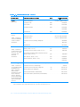
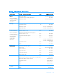
)LJXUHV
7DEOHV
Figure 1-1.
Figure 1-2.
Figure 2-1.
Figure 2-2.
Figure 2-3.
Figure 2-4.
Figure 2-5.
Figure 2-6.
Figure 3-1.
Figure 3-2.
Figure 3-3.
Figure 3-4.
Figure 3-5.
Figure 3-6.
Figure 3-7.
Figure 3-8.
Figure 3-9.
Figure 3-10.
Figure 4-1.
Figure 4-2.
Figure 5-1.
Figure B-1.
Figure B-2.
Figure B-3.
Figure C-1.
Figure C-2.
Figure C-3.
Figure C-4.
Front View of the Portable Computer . . . . . . . . . . . . . . . . . . . . . . . . 1-2
Back View of the Portable Computer. . . . . . . . . . . . . . . . . . . . . . . . . 1-3
Main Menu of Setup Program . . . . . . . . . . . . . . . . . . . . . . . . . . . . . . 2-3
System Devices Menu of Setup Program . . . . . . . . . . . . . . . . . . . . . 2-5
Security Menu of Setup Program . . . . . . . . . . . . . . . . . . . . . . . . . . . 2-7
Power Menu of Setup Program . . . . . . . . . . . . . . . . . . . . . . . . . . . . . 2-8
Boot Menu of Setup Program . . . . . . . . . . . . . . . . . . . . . . . . . . . . . 2-12
Exit Menu of Setup Program . . . . . . . . . . . . . . . . . . . . . . . . . . . . . . 2-13
AC Adapter and Power Cable . . . . . . . . . . . . . . . . . . . . . . . . . . . . . . 3-3
Checking the Battery . . . . . . . . . . . . . . . . . . . . . . . . . . . . . . . . . . . . . 3-3
Checking an Optional Device . . . . . . . . . . . . . . . . . . . . . . . . . . . . . . . 3-4
I/O Connectors for External Devices . . . . . . . . . . . . . . . . . . . . . . . . . 3-5
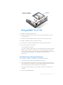
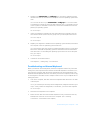
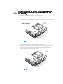
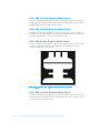
Removing the Memory Module Cover . . . . . . . . . . . . . . . . . . . . . . 3-15
Removing a Memory Module . . . . . . . . . . . . . . . . . . . . . . . . . . . . . 3-16
Installing a Memory Module . . . . . . . . . . . . . . . . . . . . . . . . . . . . . . 3-17
Removing the Memory Module Cover . . . . . . . . . . . . . . . . . . . . . . 3-27
Removing a Memory Module . . . . . . . . . . . . . . . . . . . . . . . . . . . . . 3-28
Installing a Memory Module . . . . . . . . . . . . . . . . . . . . . . . . . . . . . . 3-28
Diagnostics Menu
. . . . . . . . . . . . . . . . . . . . . . . . . . . . . . . . . . . . . 4-4
Main Screen of the Dell Diagnostics . . . . . . . . . . . . . . . . . . . . . . . . . 4-5
Diagnostics Checklist. . . . . . . . . . . . . . . . . . . . . . . . . . . . . . . . . . . . . 5-6
80-Column x 25-Line Character Set Subtest Screen . . . . . . . . . . . . . B-3
40-Column x 25-Line Character Set Subtest Screen . . . . . . . . . . . . . B-3
640 x 480 2-Color Graphics Mode Screen . . . . . . . . . . . . . . . . . . . . . B-6
VCCI Class A ITE Regulatory Mark . . . . . . . . . . . . . . . . . . . . . . . . . . C-7
VCCI Class B ITE Regulatory Mark . . . . . . . . . . . . . . . . . . . . . . . . . . C-8
MOC Class A Regulatory Mark . . . . . . . . . . . . . . . . . . . . . . . . . . . . . C-9
MOC Class B Regulatory Mark . . . . . . . . . . . . . . . . . . . . . . . . . . . . . C-9
Table 3-1.
Table 3-2.
Table 3-3.
Table 3-4.
Table 4-1.
Table 4-2.
Table 5-1.
Table 5-2.
Table A-1.
Table B-1.
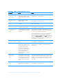
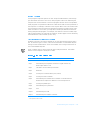
Boot Routine Indications . . . . . . . . . . . . . . . . . . . . . . . . . . . . . . . . . . 3-6
System Error Messages . . . . . . . . . . . . . . . . . . . . . . . . . . . . . . . . . . 3-7
Beep Codes . . . . . . . . . . . . . . . . . . . . . . . . . . . . . . . . . . . . . . . . . . . 3-10
IRQ Line Assignments . . . . . . . . . . . . . . . . . . . . . . . . . . . . . . . . . . . 3-13
Option Parameters. . . . . . . . . . . . . . . . . . . . . . . . . . . . . . . . . . . . . . . 4-9
Dell Diagnostics Tests . . . . . . . . . . . . . . . . . . . . . . . . . . . . . . . . . . . 4-13
International Dialing Codes . . . . . . . . . . . . . . . . . . . . . . . . . . . . . . . . 5-8
Dell Contact Numbers . . . . . . . . . . . . . . . . . . . . . . . . . . . . . . . . . . . . 5-9
Technical Specifications. . . . . . . . . . . . . . . . . . . . . . . . . . . . . . . . . . . A-1
Color Attributes . . . . . . . . . . . . . . . . . . . . . . . . . . . . . . . . . . . . . . . . . B-4
xxi
xxii
&+$37(5
,QWURGXFWLRQ
The Dell® Inspiron™ 3500 is an expandable, multimedia portable computer designed
around the Intel® Mobile Pentium® II microprocessor with MMX™ technology and
Peripheral Component Interconnect (PCI) technology. This chapter describes the
major hardware and software features of your computer, provides information about
accessing the online documentation, and tells you where to find help when needed.
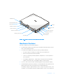
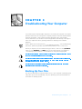
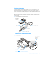
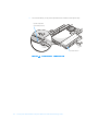
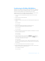
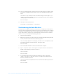
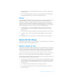
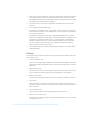
Figures 1-1 and 1-2 show the front and back views of the portable computer.
Introduction
1-1
display latch
keyboard indicator lights (3)
display close/
suspend button
display
microphone
power button
keyboard
touch pad
touch pad
buttons (2)
PC Card Slot
(2 connectors)
options bay
display release
battery bay
audio jacks (3)
AC Adapter connector
speaker
battery release latch
)LJXUH )URQW 9LHZ RI WKH 3RUWDEOH &RPSXWHU
1-2
Dell Inspiron 3500 Portable Computer Reference and Troubleshooting Guide
infrared port
internal modem port
(optional)
speaker
parallel connector
power shut off
button
serial connector
USB connector
monitor connector
PS/2 connector
fan exhaust
docking connector
air intake
lock connector
)LJXUH %DFN 9LHZ RI WKH 3RUWDEOH &RPSXWHU
+DUGZDUH)HDWXUHV
Your Dell computer has the following features:
An Intel Mobile Pentium microprocessor with MMX technology running at 233,
266, or 300 megahertz (MHz).
Full multimedia capability through the following standard features:
—
An options bay for installing a CD-ROM drive or a diskette drive
—
Built-in microphone and stereo speakers
—
Jacks for connecting external speakers, headphones, or a microphone to
your computer
—
A NeoMagic MagicMedia™ 256AV video controller with an accelerated
graphics port (AGP) with 2.5 megabytes (MB) of video memory
A 13.3- or 14.1-inch active-matrix extended graphics array (XGA)color display.
Extended battery power with a lithium ion main battery and an optional second
battery that can be used in the options bay to double battery life.
The battery charges in approximately 2 hours, using an AC power source, if the
computer is off; the battery charges in approximately 3 hours if the computer is
Introduction
1-3
on. You can expect 2 to 3 hours of battery life with a single battery and 4 to 6
hours of battery life with two batteries.
NOTES: Battery performance features such as charge time, operating time, and
life span can vary according to the conditions under which the computer and battery are used.
The battery is designed to work only with Dell Inspiron 3500 computers. Do not
attempt to use the battery with other computers.
:$51,1* 'R QRW SXQFWXUH RU LQFLQHUDWH WKH EDWWHU\ :KHQ \RXU EDW
WHU\ QR ORQJHU KROGV D FKDUJH FDOO \RXU ORFDO ZDVWH GLVSRVDO DJHQF\ RU
HQYLURQPHQWDO DJHQF\ IRU DGYLFH RQ GLVSRVLQJ RI WKH FRPSXWHU·V OLWK
LXP LRQ EDWWHU\ 7KH OLWKLXP LRQ WHFKQRORJ\ XVHG LQ WKH EDWWHU\ LV
VLJQLILFDQWO\ OHVV KD]DUGRXV WR WKH HQYLURQPHQW WKDQ WKH OLWKLXP PHWDO
WHFKQRORJ\ XVHG LQ VRPH RWKHU EDWWHULHV VXFK DV ZDWFK EDWWHULHV
1-4
Cache memory that enhances the speed of many microprocessor operations by
storing the most recently accessed contents of system memory. Dell Inspiron
3500 computers have 32 kilobytes (KB) of internal cache on the microprocessor
and 512 KB of static random-access memory (SRAM) level 2 (L2) cache.
Memory in any Dell Inspiron 3500 system can be increased up to a total of
128 MB by installing a combination of 32- or 64-MB, 3.3-volt (V) small-outline,
dual in-line memory modules (SODIMMs) in the two memory module sockets on
the system board.
The power conservation mode, save-to-disk suspend mode, which helps you conserve battery power. If the batteries run out of power, save-to-disk suspend mode
prevents data loss by copying all system data to the hard-disk drive and turning
off the computer.
An options bay and a variety of modules that extend the functionality of your
computer. You can select a CD-ROM drive, a DVD-ROM drive, Iomega® Zip drive,
or a diskette drive module, and you can use the options bay for an optional second battery.
Sixteen-bit stereo with hardware wavetable and integrated speakers and
microphone.
Support for up to two 3.3-V or 5-V PC Cards. The computer supports up to two
type I or type II cards (in any combination) or one type III card. Dell-installed
device drivers on the hard-disk drive support the operation of many standard PC
Cards.
A basic input/output system (BIOS) that resides in flash memory and can be
upgraded by diskette. A BIOS upgrade, if required, can be obtained on diskette
from Dell or can be downloaded from Dell’s TechConnect bulletin board service
(BBS). See Chapter 5, “Getting Help,” for more information on Dell’s online
services.
High-performance parallel and serial ports, and a multipurpose Personal System
(PS)/2 connector for attaching external devices. There is also a monitor connector
for attaching an external monitor to your computer.
A PS/2-compatible touch pad that gives your computer full mouse functionality.
Dell Inspiron 3500 Portable Computer Reference and Troubleshooting Guide
An infrared port for use with compatible external devices. The infrared port permits file transfers without using cable connections. Fast infrared technology is
also available.
Universal Serial Bus (USB) capability, which can simplify connecting peripheral
devices such as mice, printers, and computer speakers. The USB connector on
your computer’s side panel provides a single connection point for multiple USBcompliant devices. USB-compliant devices can be connected and disconnected
while the system is running.
The Ultra DMA/33 data transfer protocol for the advanced technology attachment
(ATA)/integrated drive electronics (IDE) hard-disk drive interface. Ultra DMA/33
allows for data transfer rates of up to 33 MB/sec.
6RIWZDUH)HDWXUHV
Dell has installed the Microsoft® Windows® 98 operating system on your hard-disk
drive. The following software is also included with your Dell computer:
A Setup program and system utilities that let you customize the operation of your
computer. Also included are drivers that tell your computer how to communicate
with various types of hardware, such as printers and external monitors. For more
information, see Chapter 2, “Customizing System Features,” and the “Software
Features” section of the System User’s Guide.
NOTE: The system utilities and drivers are available separately on a CD from Dell
for customers who installed their own version of Windows 98. See Chapter 5,
“Getting Help,” for the appropriate contact information in your location.
The Dell Diagnostics for evaluating your computer’s components and devices. For
more information, see Chapter 4, “Running the Dell Diagnostics.”
After you turn on your computer the first time, accept the software licenses agreement. Then complete the installation of your operating system.
8VLQJWKH3RZHU%XWWRQ
Under normal circumstances, you should only use the power button to turn on the
computer or to resume from suspend mode. To shut down the computer, click the
Start button in Windows 98, click Shut Down, click Shut down the computer, and
click Yes.
If the computer locks up and the operating system does not respond, press and hold
the power button until the system turns off completely (this may take several seconds). If the computer does not turn off when you press and hold the power button,
press the power shut off button on the side of the computer, next to the USB port
(see Figure 1-2).
Introduction
1-5
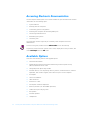
$FFHVVLQJ(OHFWURQLF'RFXPHQWDWLRQ
The Dell Inspiron 3500 System User’s Guide installed on your hard-disk drive contains
information on the following topics:
System features
Traveling with the computer
Customizing system configuration
Powering the computer and extending battery life
Connecting external devices
Maintaining the system
Contacting Dell
The guide also contains a glossary of commonly used computer terms and
abbreviations.
To access this guide, double-click the Online Guide icon on the desktop.
To print any screen from the System User’s Guide, display the screen you want, and
select Print Topic from the File menu.
$YDLODEOH2SWLRQV
Dell offers the following devices and upgrade options:
1-6
Internal 56-KB modem
DVD-ROM drive options bay module and Moving Pictures Experts Group
(MPEG)-2/DVD decode PC Card
Iomega Zip drive options bay module
External devices, such as pointing devices, printers, external monitors, external
keyboards, and numeric keypads, that connect to ports on the computer
AC adapter
Lithium ion batteries
Hard-disk drives
Network PC Cards
Dell Inspiron 3500 Port Replicator
Memory modules (32- and 64-MB capacities)
Leather and nylon carrying cases
Microphone
External speakers
Headphones
Dell Inspiron 3500 Portable Computer Reference and Troubleshooting Guide
Instructions for connecting or installing these options are contained in the System
User’s Guide or are included in the upgrade kit you received from Dell.
*HWWLQJ+HOS
If at any time you don’t understand a procedure described in this guide, or if your computer does not perform as expected, Dell provides a number of tools to help you. For
more information, see Chapter 5, “Getting Help.”
Introduction
1-7
1-8
Dell Inspiron 3500 Portable Computer Reference and Troubleshooting Guide
&+$37(5
&XVWRPL]LQJ6\VWHP)HDWXUHV
As your computing environment changes, you may want to customize the configuration of your computer. The system utilities and the Setup program let you control
various hardware and software features of your computer and allow you to monitor
and reduce power consumption when your computer is running on battery power.
This chapter explains how to access and use the system utilities and the Setup
program.
6\VWHP8WLOLWLHV
If Dell installed your operating system, the system utilities are on the hard-disk drive
that came with the computer.
NOTE: The system utilities are available separately on a CD for those who installed
their own version of the Microsoft Windows 98 operating system. To order this CD
from Dell, see Chapter 5, “Getting Help,” for the appropriate telephone number in
your location.
Use system utilities to:
Configure PC Cards
If you are using Windows 98, use the PC Card utility that comes with the operating system. Click the Start button, point to Settings, and click Control Panel.
Double-click the PC Card (PCMCIA) icon.
For more information, see the topic titled “Configuring PC Cards” in the System
User’s Guide.
Change video resolution
In Windows 98, click the Start button, point to Settings, and click Control Panel.
Double-click the Display icon and click the Settings tab. To change other video
settings, such as the refresh rate or external monitor settings, click Advanced.
For more information, see the topic titled “Adjusting Video Resolution and
Refresh Rate” in the System User’s Guide.
Customizing System Features
2-1
Adjust audio properties
In Windows 98, click the Start button, point to Settings, and then click Control
Panel. Double-click the Multimedia icon. Alternatively, right-click the Audio icon
in the taskbar.
Customize touch pad and cursor features
In Windows 98, click the Start button, point to Settings, and then click Control
Panel. Double-click the Mouse icon.
For more information, see the topic titled “Touch Pad” in the System User’s
Guide.
Check battery status
In Windows 98, see the operating system documentation for instructions on
using the battery status utility that comes with the operating system.
Manage power consumption when using a battery
For more information about saving battery power, see the topic titled “Conserving Battery Power” in the System User’s Guide.
6HWXS3URJUDP Your computer retains system configuration information in the nonvolatile randomaccess memory (NVRAM) maintained by your computer’s backup battery. Each time
you turn on your computer, the system compares the installed hardware with the system configuration information stored in NVRAM. If the system detects a discrepancy,
it generates an error message that identifies the incorrect configuration setting. The
system then prompts you to enter the Setup program to correct the setting.
You can use the Setup program as follows:
To change your system configuration information after you add, change, or
remove hardware connected to or installed inside your computer
To verify information about your computer’s current configuration, such as the
amount of system memory
To set or change user-selectable features — for example, power management or
security features
NOTE: Many of the settings that are configured in the Setup program are overridden by the settings in the Windows control panels, such as the Power
Management control panel. When your computer is running the Windows operating system, it will use the settings that are selected in the Windows control
panels rather than those set in the Setup program.
2-2
Dell Inspiron 3500 Portable Computer Reference and Troubleshooting Guide
$FFHVVLQJWKH6HWXS3URJUDP
&$87,21 7R DYRLG GDWD ORVV H[LW DQ\ DSSOLFDWLRQ SURJUDPV EHIRUH UHERRW
LQJ WKH FRPSXWHU WR HQWHU WKH 6HWXS SURJUDP
To access the Setup program, turn on the computer and press <F2> as soon as you
see the Dell logo screen and before the Windows logo screen appears. The computer
reboots automatically when you exit the Setup program.
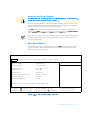
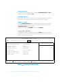
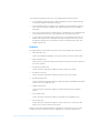
The Main menu of the Setup program shows how the computer is configured. In
addition to the Main menu (see Figure 2-1), you can also access the System Devices
menu, Security menu, Power menu, Boot menu, and Exit menu.
NOTE: When you press <F9>, the computer resets the default values for each option
in that menu. When you press <F10>, the computer saves the current values and
exits the Setup program.
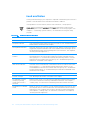
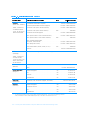
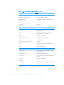
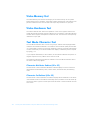
0DLQ0HQX2SWLRQV
The following subsections explain each option in the Main menu (see Figure 2-1) of
the Setup program. The same information is also available in the topic titled “Main
Menu” in the System User’s Guide.
PhoenixBIOS Setup Utility
Main
System Devices
Security
Power
System Time:
System Date:
[03:06:18]
[09/18/1998]
Floppy Drive:
Hard Disk:
1.44 MB, 3 1/2”
4100 MB
Quiet Boot:
Video Display Device:
[Enabled]
[Simul Mode]
System Memory:
Extended Memory:
640 KB
32 MB
Boot
Exit
Item Specific Help
Visit our Web site at http://www.dell.com/
F1 Help
ESC Exit
↑↓ Select Item
↔ Select Menu
F5/F6 Change Values
Enter Select
Sub-Menu
F9 Setup Defaults
F10 Save and Exit
)LJXUH 0DLQ 0HQX RI 6HWXS 3URJUDP
Customizing System Features
2-3
6\VWHP 7LPH
System Time sets the computer to the time you specify (usually the current time).
Type in the appropriate information. Use the tab key to move between the hours, minutes, and seconds fields. This option is useful if you travel between time zones.
6\VWHP 'DWH
System Date sets your system to the date you specify (usually the current date). Type
in the appropriate information. Use the tab key to move between the month, day, and
year fields.
)ORSS\ 'ULYH
Floppy Drive identifies the type of diskette drive being used by the computer. This
option has no user-selectable settings.
1.44 MB, 3 1/2” means there is a diskette drive in the options bay.
Disabled means that there is no diskette drive installed.
+DUG 'LVN
Hard Disk displays the capacity of the computer's hard-disk drive. If you install a drive
with a different capacity, the settings under this option change automatically. This
option does not have any user-selectable settings.
4XLHW %RRW
When Quiet Boot is set to Enabled (the default), the diagnostic power-on self-test
(POST) messages and summary screen do not appear at system boot. Disabled indicates that the POST messages and summary screen do appear at system boot. In
addition, if Quiet Boot is enabled, you cannot choose a boot device as the system
initializes.
9LGHR 'LVSOD\ 'HYLFH
Video Display Device allows you to specify whether video is visible only on the computer’s display (LCD Mode), only on an external monitor or projector (CRT Mode), or
on both the display and an external device simultaneously (Simul Mode, the default).
When you are using the Windows 98 operating system (rather than the Setup program), press <Fn><F8> to change the video display device.
6\VWHP 0HPRU\
System Memory displays the base amount of dynamic random-access memory
(DRAM) installed in the computer. Each computer has 640 kilobytes (KB) of base
memory. This option has no user-selectable settings.
2-4
Dell Inspiron 3500 Portable Computer Reference and Troubleshooting Guide
([WHQGHG 0HPRU\
Extended Memory displays the total amount of memory above 1 megabyte (MB).
Each computer comes standard with at least 32 MB of memory installed. If you install
or remove memory, the amount of extended memory displayed changes. This option
has no user-selectable settings.
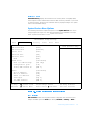
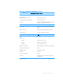
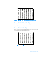
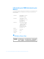
6\VWHP'HYLFHV0HQX2SWLRQV
The following subsections explain each option in the System Devices menu of the
Setup program (see Figure 2-2). The same information is also available in the topic
titled “System Devices Menu” in the System User’s Guide.
PhoenixBIOS Setup Utility
Main
System Devices
Security
Power
IDE Controller
FDD Controller
[Both]
[Enabled]
Serial Port
[Auto]
Infrared Port
[Off]
Parallel Port:
Mode
[Auto]
[ECP]
Modem Port:
Base I/O address/IRQ:
Configuration port:
16-bit DMA channel A:
16-bit DMA channel B:
[Customized]
[2F8 IRQ3]
[130]
[DMA 6]
[DMA 7]
Audio:
SB I/O address:
WSS I/O address:
AdLib I/O address:
Interrupt:
1st DMA channel:
2nd DMA channel:
[Customized]
[220]
[530]
[388]
[IRQ 5]
[DMA 0]
[DMA 1]
F1 Help
ESC Exit
↑↓ Select Item
↔ Select Menu
Boot
Exit
F5/F6 Change Values
Enter Select
Sub-Menu
Item Specific Help
F9 Setup Defaults
F10 Save and Exit
)LJXUH 6\VWHP 'HYLFHV 0HQX RI 6HWXS 3URJUDP
,'( &RQWUROOHU
IDE Controller enables the integrated local-bus integrated drive electronics (IDE)
adapter. Available options are Both (the default), Disabled, or Primary. If Both is
Customizing System Features
2-5
selected, you can access both the hard-disk drive and the CD-ROM drive. If Primary
is selected, only the hard-disk drive is accessible.
)'' &RQWUROOHU
FDD Controller enables the diskette-drive controller. If this option is set to Disabled,
the diskette drive is unavailable.
6HULDO 3RUW
Serial Port lets you map the address of the serial port to avoid address conflicts with
other devices or disable the port for security. The default is Auto, and the default base
input/output (I/O) and interrupt request (IRQ) address is 3F8 IRQ4. Dell recommends
that you retain the default.
NOTE: If there is a conflict between two or more addresses, an asterisk appears next
to the port type in the System Devices menu.
,QIUDUHG 3RUW
Infrared Port lets you map the address of the infrared port to avoid address conflicts
with other devices. The default is Off. Dell recommends that you retain the default
settings.
NOTE: If there is a conflict between two or more addresses, an asterisk appears next
to the port type in the System Devices menu.
3DUDOOHO 3RUW
Parallel Port controls whether the computer’s parallel port acts as advanced
technology (AT)-compatible (normal), Personal System (PS)/2-compatible (bidirectional), Enhanced Parallel Port (EPP)-compatible, or Extended Capabilities Port (ECP)compatible. The basic Parallel Port options are Customized, Off, and Auto. The
default is Auto. Additional possible Mode settings are Normal mode, EPP, and Bidirectional. The default mode is ECP.
When Parallel Port is set to Off, you can disable the port and free its assigned LPT
address for another device.
When Parallel Port is set to Customized, you can configure the port settings. The
default base I/O address is 378h. If for some reason you need to change the parallel
port address and/or direct memory address (DMA) channel, be careful not to create a
conflict with the address or DMA channel of the infrared port.
NOTE: If there is a conflict between two or more addresses, an asterisk appears next
to the port type in the System Devices menu.
2-6
Dell Inspiron 3500 Portable Computer Reference and Troubleshooting Guide
0RGHP 3RUW
The Modem Port lets you configure the internal modem and map the address of the
modem port to avoid address conflicts with other devices. The default settings for the
Dell-installed optional internal modem are shown in Figure 2-2. Dell recommends that
you retain the default settings.
NOTE: Modem port settings will only appear in the Setup program if you have the
optional internal modem installed in your computer. If there is no internal modem, this
section will not appear.
$XGLR
Audio settings allow you to configure the audio system. The default settings for the
audio system are shown in Figure 2-2. Dell recommends that you retain the default
settings.
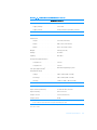
6HFXULW\0HQX2SWLRQV
The following subsections explain each option in the Security menu of the Setup program (see Figure 2-3). The same information is also available in the topic titled
“Security Menu” in the System User’s Guide.
PhoenixBIOS Setup Utility
Main
System Devices
Security
Power
Boot
Exit
Item Specific Help
System Password is
Clear
Set System Password
[Enter]
Password On Boot
[Disabled]
F1 Help
ESC Exit
↑↓ Select Item
↔ Select Menu
F5/F6 Change Values
Enter Select
Sub-Menu
F9 Setup Defaults
F10 Save and Exit
)LJXUH 6HFXULW\ 0HQX RI 6HWXS 3URJUDP
Customizing System Features
2-7
6\VWHP 3DVVZRUG LV
If no system password has been set, the setting for System Password is is Clear.
Otherwise, the setting displayed is Set.
6HW 6\VWHP 3DVVZRUG
Press <Enter> to set up a new system password, and then follow the instructions on
your screen. This password restricts access to the Setup program settings.
3DVVZRUG 2Q %RRW
When the Password On Boot option is enabled, you must enter a password before
the computer loads the operating system into memory. To enable this option, the
System Password is option must be set.
Settings for this option are Disabled (the default) and Enabled.
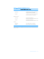
3RZHU0HQX2SWLRQV
The following subsections explain each option in the Power menu of the Setup program (see Figure 2-4). The same information is also available in the topic titled “Power
Menu” in the System User’s Guide.
PhoenixBIOS Setup Utility
Main
System Devices
Security
Power
Power Management Mode
[Customized]
CPU Throttling:
Standby Time-out:
Suspend Time-out:
[Off]
[Disabled]
[Disabled]
Suspend Mode
[Save to RAM]
Resume On Modem Ring:
Resume On Time of Day:
Resume Time:
[Disabled]
[Disabled]
[00:00:00]
F1 Help
ESC Exit
↑↓ Select Item
↔ Select Menu
Boot
Exit
F5/F6 Change Values
Enter Select
Sub-Menu
)LJXUH 3RZHU 0HQX RI 6HWXS 3URJUDP
2-8
Dell Inspiron 3500 Portable Computer Reference and Troubleshooting Guide
Item Specific Help
F9 Setup Defaults
F10 Save and Exit
3RZHU 0DQDJHPHQW 0RGH
NOTE: The power management settings of the Windows 98 operating system take
precedence over the settings described here. For more information see “Using
Microsoft Windows 98 to Conserve Battery Power,” in the System User’s Guide.
Select Max Speed to completely disable power management for maximum performance. The CPU Throttling option is set automatically to Off.
Customized (the default) allows you to control each power management setting.
Select Min Power if you want the computer to get the maximum battery life. When
this setting is selected, the Standby Time-Out option is set automatically to 1
minute, and the Suspend Time-Out option is set automatically to 5 minutes. The
CPU Throttling option is set automatically to On.
Select Balanced if you do not want the computer to go into Suspend Mode. When
this setting is selected, the Standby Time-Out option is set automatically to 4 minutes, and the Suspend Time-Out option is set automatically to Disabled. The CPU
Throttling option is set automatically to Off.
&38 7KURWWOLQJ
NOTE: The power management settings of the Windows 98 operating system take
precedence over the settings described here. For more information see “Using
Microsoft Windows 98 to Conserve Battery Power,” in the System User’s Guide.
CPU Throttling allows the computer to slow down the microprocessor automatically
if it is not being used. Settings for this option are:
On — Allows the computer to slow down the microprocessor when it is inactive
Off (the default) — Keeps the microprocessor running at its normal operating
speed regardless of microprocessor inactivity
To increase battery operating time, set the CPU Throttling option to On.
When the CPU Throttling option is enabled and the microprocessor is inactive, the
computer slows the microprocessor to save power.
NOTES: Some communications software may not work properly when CPU Throttling is enabled. Dell recommends that you set CPU Throttling to Off if you are using
communications software.
Interactive application programs should function well when CPU Throttling is
enabled. (Examples of interactive programs include spreadsheet, text editor, graphics
design, entertainment, educational, and utility programs.) However, you may experience performance degradation when recalculating a large spreadsheet or during an
extensive screen redraw in a graphical program. Benchmark utilities may not perform
as intended when doing microprocessor speed tests. If the software you use suffers
significant performance degradation, set CPU Throttling to Off.
Customizing System Features
2-9
6WDQGE\ 7LPH2XW
NOTE: The power management settings of the Windows 98 operating system take
precedence over the settings described here. For more information see “Using
Microsoft Windows 98 to Conserve Battery Power,” in the System User’s Guide.
Standby mode conserves battery power by stopping some computer activity, but
leaves the computer ready to resume operations immediately. Use standby mode
when you leave the computer unattended for less than a few minutes. Press
<Fn><Esc> to enter standby mode when you are in Windows 98. Resume normal
computer activity by moving the cursor or pressing any key on the built-in keyboard
(the computer takes less than a second to return to normal operation).
The Standby Time-Out option lets you determine how long the computer remains
idle (no I/O activity) before activating standby mode to conserve battery power. Settings for this option are Disabled, 1 min., 2 min., 4 min., 6 min., 8 min., 12 min.,
and 16 min.
To increase battery operating time, set this option to a lower number of minutes.
Press any key on the built-in keyboard to resume normal computer operation.
If the time delay you set for standby mode is greater than the delay set for suspend
mode, the computer enters standby mode first. For instance, if Standby Time-Out is
set for 8 minutes and Suspend Time-Out is set for 5 minutes, the computer enters
standby mode after 8 minutes of no I/O activity and then enters save-to-disk suspend
mode 5 minutes later.
NOTE: Set this option to Disabled if it causes compatibility problems with your
software.
6XVSHQG 7LPH2XW
NOTE: The power management settings of the Windows 98 operating system take
precedence over the settings described here. For more information see “Using
Microsoft Windows 98 to Conserve Battery Power,” in the System User’s Guide.
Suspend Time-Out lets you determine how long the computer remains idle (no I/O
activity) before activating save-to-disk suspend mode. Settings for this option are Disabled, 5 min., 10 min., 15 min., 20 min., 30 min., 40 min., and 60 min.
To increase battery operating time, set this option to a lower number of minutes.
If the time delay you set for suspend mode is greater than the delay set for standby
mode, the computer enters save-to-disk suspend mode first. For instance, if Suspend Time-Out is set for 10 minutes and Standby Time-Out is set for 4 minutes,
the computer enters save-to-disk suspend mode after 10 minutes of no I/O activity
and then enters standby mode 4 minutes later.
NOTE: Set this option to Disabled if it causes compatibility problems with your
software.
If you are not in the Setup program, you can activate save-to-RAM suspend mode at
any time by pressing <Fn><Esc>. Alternatively, click the Start button, and then click
Suspend. Press the power button to resume normal computer operation.
2-10
Dell Inspiron 3500 Portable Computer Reference and Troubleshooting Guide
You can activate save-to-disk suspend mode by pressing <Fn><a> (or <Fn><q> on
the French keyboard). Press the power button and hold it down for a second or two to
turn on the computer and resume normal operation.
6XVSHQG 0RGH
NOTE: The power management settings of the Windows 98 operating system take
precedence over the settings described here. For more information see “Using
Microsoft Windows 98 to Conserve Battery Power,” in the System User’s Guide.
The Suspend Mode category has two options—Save to RAM and Save to Disk.
Save to RAM (the default) suspend mode conserves battery power by stopping
almost all computer activity, but leaves the computer ready to resume operations in
seconds. Select the Save to RAM option whenever you leave the computer unattended for more than a few minutes. Resume normal computer activity by pressing
the power button (the computer may take several seconds to return to normal
operation).
Save to Disk suspend mode copies all system data to a reserved area on the harddisk drive and then turns off all power to the computer. When you resume normal
operation, the same programs will be running and the same files will be open that
were loaded before you activated this mode. Use Save to Disk suspend mode to conserve battery power or to preserve system data by quickly saving it to the hard-disk
drive if you are about to run out of battery power.
5HVXPH 2Q 0RGHP 5LQJ
Setting this option to Enabled tells the computer to resume normal operation when
an incoming call is detected by a modem and the computer is in standby mode. The
default setting is Disabled. To use this option, Suspend Mode must be set to Save
to RAM. Resume On Modem Ring does not work if Suspend Mode is set to Save
to Disk.
5HVXPH 2Q 7LPH RI 'D\
When the Resume On Time of Day option is set to Enabled, the computer resumes
normal operation at the time specified in the Resume Time field after being in
standby mode. The default for this option is Disabled. To use this option, Suspend
Mode must be set to Save to RAM. Resume On Time of Day does not work if Suspend Mode is set to Save to Disk.
5HVXPH 7LPH
Resume Time lets you specify a time when the computer should get out of standby
mode and resume normal operation. To use this option, Suspend Mode must be set
to Save to RAM. Resume Time does not work if Suspend Mode is set to Save to
Disk.
Customizing System Features
2-11
%RRW0HQX2SWLRQV
The following subsections explain each option in the Boot menu of the Setup program (Figure 2-5). The selections you make in this menu determine which disk device
the computer uses to find the software needed to start the operating system. The
same information is also available in the topic titled “Boot Menu” in the System
User’s Guide.
PhoenixBIOS Setup Utility
Main
System Devices
Security
Power
Boot
Exit
Item Specific Help
1. [Diskette Drive]
2. [Hard Drive]
3. [CD-ROM Drive]
F1 Help
ESC Exit
↑↓ Select Item
↔ Select Menu
F5/F6 Change Values
Enter Select
Sub-Menu
F9 Setup Defaults
F10 Save and Exit
)LJXUH %RRW 0HQX RI 6HWXS 3URJUDP
To select the boot device, use the up- or down-arrow key; then press <F6> to move
the device up the list or <F5> to move the device down the list.
If Diskette Drive appears first (the default), the computer attempts to boot first from
a bootable diskette. If it does not detect a diskette in the diskette drive, the computer
tries to boot from the hard-disk drive. If there is a diskette in the diskette drive, but the
diskette does not have the required boot files, an error message is displayed.
Hard Drive first causes the computer to boot only from the hard-disk drive. If it fails to
boot from the hard-disk drive, the computer does not attempt to boot from the diskette drive.
CD-ROM Drive first causes the computer to attempt booting first from a bootable CD.
If it does not detect a bootable CD in the CD-ROM drive, the computer tries to boot
from the hard-disk drive. If there is a CD in the CD-ROM drive, but the CD does not
have the required boot files, an error message is displayed.
2-12
Dell Inspiron 3500 Portable Computer Reference and Troubleshooting Guide
([LW0HQX2SWLRQV
The following subsections explain each option in the Exit menu of the Setup program
(Figure 2-6). The selections you make in this menu determine which disk device the
computer uses to find the software needed to start the operating system. The same
information is also available in the topic titled “Exit Menu” in the System User’s
Guide.
PhoenixBIOS Setup Utility
Main
System Devices
Security
Power
Boot
Exit
Item Specific Help
Save Changes and Exit
Discard Changes and Exit
Load Factory Defaults
Load Last Saved Values
Save Changes
F1 Help
ESC Exit
↑↓ Select Item
↔ Select Menu
F5/F6 Change Values
Enter Execute Command
F9 Setup Defaults
F10 Save and Exit
)LJXUH ([LW 0HQX RI 6HWXS 3URJUDP
6DYH &KDQJHV DQG ([LW
After you have changed a setting in the Setup program, select this option to save the
changes into NVRAM and exit the Setup program.
If you try to exit the Setup program without saving your changes, you are prompted to
save.
'LVFDUG &KDQJHV DQG ([LW
Select this option only if you do not want to save the changes you made in the Setup
program.
Customizing System Features
2-13
/RDG )DFWRU\ 'HIDXOWV
Load Factory Defaults lets you select the default settings for each option in the
Setup program. Press <Enter> when prompted to continue. Then you can make more
changes in the Setup program or select Save Changes and Exit.
/RDG /DVW 6DYHG 9DOXHV
Load Last Saved Values lets you discard the settings you have made and restore the
settings you previously saved. Press <Enter> when prompted to continue.
6DYH &KDQJHV
Save Changes saves your settings without exiting the Setup program. Press <Enter>
when prompted to continue, and then return to other menus to make changes.
&UHDWLQJWKH6DYHWR'LVN6XVSHQG)LOH
If you are installing a new hard-disk drive or if you are rebuilding a hard-disk drive that
has corrupted software and you want to be able to use the save-to-disk suspend
mode, you must use the phdisk.exe utility on your System Utilities diskette to create
a save-to-disk suspend file. When save-to-disk suspend mode is activated, all system
data is stored in this file.
To create the save-to-disk suspend file, follow these steps:
1.
Insert the Microsoft Boot Disk Windows 98 Series diskette into the diskette
drive.
2.
Restart the system.
3.
When the Microsoft Windows 98 Startup Menu appears, select Start computer with CD-ROM Support and press <Enter>.
4.
When the MS-DOS® prompt appears, insert the Dell Inspiron 3500 System Software CD into the CD-ROM or DVD-ROM drive.
5.
At the MS-DOS prompt, type d: and press <Enter>, where d is the drive letter
for your CD-ROM or DVD-ROM drive.
Your MS-DOS prompt changes from an A:\> to a D:\>, assuming D is the drive
letter for your CD-ROM or DVD-ROM drive.
6.
Type cd\utilities and press <Enter>.
7.
Type PHDISK /CREATE /FILE and press <Enter>.
NOTE: Make sure there is a space between PHDISK /CREATE and /FILE.
The utility calculates the size of the file, in kilobytes, based on the amount of system memory in your computer, plus 2 MB to handle video memory and additional
system requirements.
8.
2-14
Follow the instructions on your screen to create the save-to-disk suspend file.
Dell Inspiron 3500 Portable Computer Reference and Troubleshooting Guide
To check the size of the save-to-disk suspend file, at an MS-DOS prompt type
PHDISK /INFO and press <Enter>
If you need to delete the save-to-disk suspend file, at an MS-DOS prompt type
PHDISK /DELETE /FILE and press <Enter>.
5HLQVWDOOLQJWKH6\VWHP8VHU·V*XLGH
If needed, you can download the Dell Inspiron 3500 System User’s Guide from Dell’s
World Wide Web (WWW) site at http://www.dell.com/:
1.
Click the Support icon.
The Dell Support main menu appears.
2.
Click Troubleshoot Your Dell System, and then locate the link to the Inspiron
page.
3.
Select 3500.
4.
Click Technical Information, and then click Documentation.
5.
Click System User’s Guide.
6.
When prompted, save the file to your hard-disk drive.
Customizing System Features
2-15
2-16
Dell Inspiron 3500 Portable Computer Reference and Troubleshooting Guide
&+$37(5
7URXEOHVKRRWLQJ<RXU&RPSXWHU
If your Dell Inspiron 3500 portable computer is not working as expected, this chapter
provides initial checks for solving basic computer problems as well as detailed troubleshooting procedures. It lists system messages and beep codes, their possible
causes, and actions you can take to resolve any problems indicated by a message or
code. This chapter also offers general guidelines for analyzing some software
problems.
NOTES: When you see the question “Is the problem resolved?” in a troubleshooting
procedure, repeat the operation that caused the problem to see if it still occurs.
Before you begin any of the troubleshooting procedures, make sure the Quiet Boot
option is set to Disabled in the Main menu of the Setup program. See Chapter 2,
“Customizing System Features,” for information on using the Setup program.
&$87,21 7KH RQO\ WLPH \RX VKRXOG HYHU DFFHVV WKH LQVLGH RI \RXU FRPSXWHU
LV ZKHQ \RX DUH LQVWDOOLQJ PHPRU\ PRGXOHV
&$87,21 :DLW VHFRQGV DIWHU WXUQLQJ RII WKH FRPSXWHU EHIRUH GLVFRQQHFW
LQJ D SHULSKHUDO GHYLFH RU UHPRYLQJ D PHPRU\ PRGXOH WR KHOS SUHYHQW
SRVVLEOH GDPDJH WR WKH V\VWHP ERDUG
&$87,21 6HH ´3URWHFWLQJ $JDLQVW (OHFWURVWDWLF 'LVFKDUJHµ LQ WKH VDIHW\
LQVWUXFWLRQV DW WKH IURQW RI WKLV JXLGH
%DFNLQJ8S<RXU)LOHV
You can lose data when a computer failure occurs. If your computer is behaving erratically, back up your files immediately. See your operating system documentation for
instructions on backing up files.
Troubleshooting Your Computer
3-1
%DVLF&KHFNV
The following procedure leads you through the checks necessary to solve some basic
computer problems:
1.
Is your computer wet or damaged?
Yes. Go to “Troubleshooting a Wet Computer” or “Troubleshooting a Damaged
Computer” found later in this chapter.
No. Go to step 2.
2.
Perform the steps in the next subsection, “Checking Connections.”
Is the problem resolved?
Yes. A connection to your computer was loose. The problem is resolved.
No. Go to step 3.
3.
Perform the steps found in “Look and Listen” found later in this chapter.
Did your computer complete the boot (start-up) routine?
NOTE: The boot routine is the operating system’s attempt to load its files into
memory from the boot-up sector on the hard-disk drive or bootable diskette.
Yes. Go to step 4.
No. Call Dell for technical assistance. (See Chapter 5, “Getting Help,” for
instructions.)
4.
Did you receive a system message or beep code?
A single beep always sounds during the boot routine when the speaker is tested.
Yes. Go to “Messages and Codes” found later in this chapter.
No. Go to step 5.
5.
Verify the system setup settings as explained in Chapter 2, “Customizing System
Features.”
Is the problem resolved?
Yes. The system configuration information was incorrect. The problem is
resolved.
No. Go to step 6.
6.
3-2
Run the Dell Diagnostics. (See Chapter 4, “Running the Dell Diagnostics.”)
Dell Inspiron 3500 Portable Computer Reference and Troubleshooting Guide
&KHFNLQJ&RQQHFWLRQV
Loose or improperly connected cables are likely sources of problems for your computer, external monitor, or other peripherals (such as a printer, external keyboard, or
mouse). A quick check of all cable connections can easily solve these problems. If the
connector has two small screws, make sure the screws are tight. In addition, check
for damaged or frayed cables and for bent pins on connectors.
Be sure the following items are properly connected or installed, as shown in Figures
3-1 through 3-4:
The AC adapter and the AC power cable
AC adapter
connector
AC adapter cable
LED
AC adapter
AC power cable
)LJXUH $& $GDSWHU DQG 3RZHU &DEOH
The main battery
battery bay latch
(released
position)
battery
battery bay
)LJXUH &KHFNLQJ WKH %DWWHU\
Troubleshooting Your Computer
3-3
The second battery or any other optional device installed in the options bay
options bay latch
(unlocked position)
optional device
)LJXUH &KHFNLQJ DQ 2SWLRQDO 'HYLFH
3-4
Dell Inspiron 3500 Portable Computer Reference and Troubleshooting Guide
Cables that connect external devices through the input/output (I/O) connectors
and ports on the computer.
PS/2 keyboard/mouse
connector
infrared port
optional internal
modem port
AC Adapter
connector
USB
connector
serial port
parallel port
monitor
connector
docking
connector
audio jacks (3)
)LJXUH ,2 &RQQHFWRUV IRU ([WHUQDO 'HYLFHV
Troubleshooting Your Computer
3-5
/RRNDQG/LVWHQ
Looking at and listening to your computer is important in determining the source of a
problem. Look and listen for the indications described in Table 3-1.
If the problem is still not resolved, see the next subsection, “Setup Options.”
NOTE: Before you begin any of the troubleshooting procedures, make sure the
Quiet Boot option is set to Disabled in the Main menu of the Setup program. See
Chapter 2, “Customizing System Features,” for information on using the Setup
program.
7DEOH %RRW 5RXWLQH ,QGLFDWLRQV
/RRN IRU
$FWLRQ
An error message
See “Messages and Codes” found later in this chapter.
The power indicator
If the computer’s power status LED does not come on, see “Troubleshooting a
Power Failure” found later in this chapter.
The keyboard indicators
Press the <Num Lock> key, the <Caps Lock> key, and the <Scroll Lock> key to
toggle their respective indicator LEDs. If the indicator LEDs do not light up, run
the Keyboard test group in the Dell Diagnostics (for instructions, see Chapter 4,
“Running the Dell Diagnostics”).
The diskette-drive access
indicator
The diskette-drive access indicator should light up when data is accessed on
the diskette drive. You can test this indicator by inserting a diskette into the
drive, typing dir a: at an MS-DOS prompt, and pressing <Enter>. If the diskette-drive access indicator does not light up, see “Troubleshooting the Diskette Drive” found later in this chapter.
The CD-ROM/hard-disk
drive access indicator
The CD-ROM/hard-disk drive access indicator should light up when data is
accessed on the CD-ROM drive or the hard-disk drive. You can test this indicator by typing dir c: at an MS-DOS prompt and pressing <Enter>. If the
CD-ROM/hard-disk drive access indicator does not light up, see “Troubleshooting the Hard-Disk Drive” or “Troubleshooting the CD-ROM or DVD-ROM Drive”
found later in this chapter.
/LVWHQ IRU
$FWLRQ
A series of beeps
See “Messages and Codes” found later in this chapter.
An unfamiliar constant
scraping or grinding
sound when a drive is
accessed
Make sure the sound is not caused by the application program that is running.
The sound could also be caused by a hardware malfunction. See Chapter 5,
“Getting Help,” for instructions on obtaining technical assistance from Dell.
The absence of a familiar
sound
When you turn on the computer, you can hear the hard-disk drive spin up, and
the computer tries to access the boot files from the hard-disk drive or the diskette drive. If your computer does not boot, call Dell for technical assistance.
(See Chapter 5, “Getting Help,” for instructions.) Otherwise, see Chapter 4,
“Running the Dell Diagnostics.”
NOTE: For the full name of an abbreviation or acronym used in this table, see the Glossary in the System User’s Guide.
3-6
Dell Inspiron 3500 Portable Computer Reference and Troubleshooting Guide
6HWXS2SWLRQV
You can easily correct certain system problems by verifying the settings for setup
options. When you boot the computer, it compares the system configuration information with the current hardware configuration. If the computer’s hardware configuration
doesn’t match the information recorded by the system setup options, an error message
may appear on the display.
To fix this problem, correct the appropriate options in the Setup program. See
Chapter 2, “Customizing System Features,” for detailed information about the Setup
program and its options.
If, after checking the setup options, you have not resolved the problem, see Chapter 4,
“Running the Dell Diagnostics.”
0HVVDJHVDQG&RGHV
The application programs, operating system, and the computer itself are capable of
identifying problems and alerting you to them. When this occurs, a message may
appear on the computer’s display or an external monitor (if one is attached), or a beep
code may sound.
If an error message appears on the display or external monitor, make a note of the
message. See Table 3-2 for an explanation of the message and suggestions for correcting any errors. The system messages are listed alphabetically.
NOTE: If the message is not listed in Table 3-2, check the documentation for the application programs that were running at the time the message appeared and/or the
operating system documentation for an explanation of the message and a recommended action.
7DEOH 6\VWHP (UURU 0HVVDJHV
0HVVDJH
&DXVH
$FWLRQ
Diskette drive
A error
A connector may be loose or
the diskette may be faulty.
If the diskette-drive access indicator lights up when
you access a file on the diskette, but you still get
this error message, try a different diskette. If the
problem persists, shut down the computer, remove
the drive completely, and then reinsert it. Turn the
computer back on, and check for the error message.
If the problem is still not resolved, see “Troubleshooting the Diskette Drive” found later in this
chapter.
NOTE: For the full name of an abbreviation or acronym used in this table, see the Glossary in the System User’s Guide.
Troubleshooting Your Computer
3-7
7DEOH 6\VWHP (UURU 0HVVDJHV FRQWLQXHG
0HVVDJH
&DXVH
$FWLRQ
Extended RAM
failed at offset: nnnn
Extended memory is not
configured properly or has
failed at the memory address
nnnn.
Call Dell for technical assistance. (For instructions,
see Chapter 5, “Getting Help.”)
Failing bits:
nnnn
Memory failed at RAM
address nnnn.
Call Dell for technical assistance. (For instructions,
see Chapter 5, “Getting Help.”)
Fixed disk 0
failure
The hard-disk drive failed to
initialize.
See “Troubleshooting the Hard-Disk Drive” found
later in this chapter.
Fixed disk controller failure
The hard-disk drive
controller may be faulty.
Call Dell for technical assistance. (For instructions,
see Chapter 5, “Getting Help.”)
Incorrect drive
A type—run
Setup
The diskette drive is not identified properly in the Setup
program.
Shut down the computer, remove the drive completely, and then reinsert it. Turn the computer back
on, and check for the error message.
If the problem persists, reboot the computer and
press <F2> as soon as you see the Dell logo
screen to enter the Setup program. Write down the
setting for FDD Controller in the Main menu. Then
call Dell for technical assistance. (For instructions,
see Chapter 5, “Getting Help.”)
Keyboard controller error
The keyboard controller is
faulty.
Call Dell for technical assistance. (For instructions,
see Chapter 5, “Getting Help.”)
Keyboard error
If an external keyboard is
being used, a cable or connector may be loose or the
keyboard may be faulty.
If the built-in keyboard is
being used, it may be faulty.
A key on the built-in keyboard may have been
pressed while the computer
was booting.
Run the Stuck Key Test in the Dell Diagnostics. (For
instructions, see Chapter 4, “Running the Dell
Diagnostics.”)
Operating
system not
found
The operating system may
be corrupted. Or, the operating system cannot be found
on the hard-disk drive or on
the diskette in the diskette
drive.
Reinstall the operating system. See the documentation that came with the operating system. If the
problem is still not resolved, call Dell for technical
assistance. (For instructions, see Chapter 5, “Getting Help.”)
Parity check 1
nnnn
A parity error was found in
the system bus at address
nnnn.
Call Dell for technical assistance. (For instructions,
see Chapter 5, “Getting Help.”)
NOTE: For the full name of an abbreviation or acronym used in this table, see the Glossary in the System User’s Guide.
3-8
Dell Inspiron 3500 Portable Computer Reference and Troubleshooting Guide
7DEOH 6\VWHP (UURU 0HVVDJHV FRQWLQXHG
0HVVDJH
&DXVH
$FWLRQ
Parity check 2
nnnn
A parity error was found in
the I/O bus at address nnnn.
Call Dell for technical assistance. (For instructions,
see Chapter 5, “Getting Help.”)
Real time clock
error
The CMOS battery that
supports data stored in
NVRAM may be dead.
Call Dell for technical assistance. (For instructions,
see Chapter 5, “Getting Help.”)
Shadow RAM
failed at offset: nnnn
Shadow RAM failed at
address nnnn.
Call Dell for technical assistance. (For instructions,
see Chapter 5, “Getting Help.”)
CMOS battery is
dead—Replace
and run Setup
The CMOS battery does not
have enough charge to
power the computer.
Call Dell for technical assistance. (For instructions,
see Chapter 5, “Getting Help.”)
System cache
error—cache
disabled
The primary cache internal to
the microprocessor has
failed.
Call Dell for technical assistance. (For instructions,
see Chapter 5, “Getting Help.”)
System CMOS
checksum bad—
run Setup
The BIOS has been updated.
Reboot the computer and press <F2> as soon as
you see the Dell logo screen to enter the Setup program and reconfigure the system. If the problem
persists, call Dell for technical assistance. (For
instructions, see Chapter 5, “Getting Help.”)
System RAM
failed at offset: nnnn
System RAM failed at
address nnnn in the 64-KB
block at which the error was
detected.
Call Dell for technical assistance. (For instructions,
see Chapter 5, “Getting Help.”)
System timer
error
A chip on the system board
may be malfunctioning.
Run the System Set test group and the Keyboard
Controller Test in the Dell Diagnostics. (For
instructions, see Chapter 4, “Running the Dell
Diagnostics.”)
CMOS has been corrupted or
modified, possibly by an
application program that
changes data stored in
CMOS.
NOTE: For the full name of an abbreviation or acronym used in this table, see the Glossary in the System User’s Guide.
6\VWHP%HHS&RGHV
When errors occur during the boot routine that cannot be reported on the built-in display or on an external monitor (if attached), the computer may emit a series of beeps
that identify the problem. The beep code is a pattern of sounds: for example, one
beep, followed by a burst of three beeps, followed by a single beep, and then another
burst of three beeps (code 1-3-1-3) means that the computer was unable to read data
from the keyboard. This information is important to the Dell support staff if you need
to call for technical assistance.
When a beep code is emitted, write it down on a copy of the Diagnostics Checklist
found in Chapter 5, and then look it up in Table 3-3. If you are unable to resolve the
Troubleshooting Your Computer
3-9
problem by looking up the meaning of the beep code, use the Dell Diagnostics to
identify a more serious cause. (See Chapter 4, “Running the Dell Diagnostics.”) If you
are still unable to resolve the problem, call Dell for technical assistance. (See
Chapter 5, “Getting Help,” for instructions.)
.
7DEOH %HHS &RGHV
0HVVDJH
&DXVH
$FWLRQ
1-2-2-3
ROM BIOS checksum failure
Run the System Set test group in the Dell Diagnostics.
(See Chapter 4, “Running the Dell Diagnostics,” for
instructions.) If the program does not load, call Dell for
technical assistance. (For instructions, see Chapter 5,
“Getting Help.”)
1-3-1-1
DRAM refresh failure
Run the System Set test group in the Dell Diagnostics.
(See Chapter 4, “Running the Dell Diagnostics,” for
instructions.) If the program does not load, call Dell for
technical assistance. (For instructions, see Chapter 5,
“Getting Help.”)
1-3-1-3
Keyboard controller test failure
Run the Keyboard Controller Test in the Dell Diagnostics. (For instructions, see Chapter 4, “Running the Dell
Diagnostics.”)
1-3-4-1
RAM failure on address line nnnn
Run the RAM test group in the Dell Diagnostics. (See
Chapter 4, “Running the Dell Diagnostics,” for instructions.) If the program does not load, call Dell for technical assistance. (For instructions, see Chapter 5,
“Getting Help.”)
1-3-4-3
RAM failure on data bits nnnn of
the high byte on the memory bus
Run the RAM test group in the Dell Diagnostics. (See
Chapter 4, “Running the Dell Diagnostics,” for instructions.) If the program does not load, call Dell for technical assistance. (For instructions, see Chapter 5,
“Getting Help.”)
1-4-1-1
RAM failure on data bits nnnn of
the low byte on the memory bus
Run the RAM test group in the Dell Diagnostics. (See
Chapter 4, “Running the Dell Diagnostics,” for instructions.) If the program does not load, call Dell for technical assistance. (For instructions, see Chapter 5,
“Getting Help.”)
2-1-2-3
Check ROM copyright notice
failure
Run the System Set test group in the Dell Diagnostics.
(See Chapter 4, “Running the Dell Diagnostics,” for
instructions.) If the program does not load, call Dell for
technical assistance. (For instructions, see Chapter 5,
“Getting Help.”)
2-2-3-1
Interrupt mask register failure
Call Dell for technical assistance. (For instructions, see
Chapter 5, “Getting Help.”)
NOTE: For the full name of an abbreviation or acronym used in this table, see the Glossary in the System User’s Guide.
3-10
Dell Inspiron 3500 Portable Computer Reference and Troubleshooting Guide
)LQGLQJ6RIWZDUH6ROXWLRQV
Because most computers have several application programs installed in addition to
the operating system, isolating a software problem can be confusing. Software errors
can also appear to be hardware malfunctions at first. Software problems can result
from the following circumstances:
Improper installation or configuration of a program
Input errors
Drivers that may conflict with certain application programs
Memory conflicts resulting from the use of terminate-and-stay-resident (TSR)
programs, such as drivers
Interrupt conflicts between devices
You can confirm that a computer problem is caused by software by first running the
System Set test group as described in Chapter 4, “Running the Dell Diagnostics.” If
all tests in the test group complete successfully, the error condition is most likely
caused by software.
The following subsections provide general guidelines for analyzing some software
problems. For detailed troubleshooting information on a particular program, see the
documentation that accompanied the software or consult the support service for the
software.
,QVWDOOLQJDQG&RQILJXULQJ6RIWZDUH When you obtain software, check it for viruses using virus-scanning software before
installing it on the computer’s hard-disk drive. Viruses can quickly use all available system memory, damage and/or destroy data stored on the hard-disk drive, and
permanently affect the performance of the programs they infect. Several commercial
virus-scanning programs are available for purchase, and most bulletin board services
(BBSs) archive freely distributed virus-scanning programs that you can download with
a modem.
Before installing a program, read its documentation to learn how the program works,
what hardware it requires, and what its defaults are. A program usually includes
installation instructions in its accompanying documentation and a software installation
routine on its program diskettes.
The software installation routine assists you in transferring the appropriate program
files to the computer’s hard-disk drive. Installation instructions may provide details
about how to configure the operating system to successfully run the program. Always
read the installation instructions before running a program’s installation routine. If you
are instructed to modify the start-up files, see the documentation that came with the
operating system for instructions.
When you run the installation routine, be prepared to respond to prompts for information about how the computer’s operating system is configured, what type of
computer you have, and what peripherals are connected to the computer.
Troubleshooting Your Computer
3-11
6WDUW8S )LOHV
Whenever you start or reboot the computer, the operating system executes commands from its start-up files.
These files contain commands that automatically configure the operating system by
setting system parameters, starting memory-resident programs, and loading device
driver software. If you experience program conflicts or memory error messages,
check the commands for memory-resident programs in the start-up files of the operating system. (For information on start-up files, see the documentation that came
with the operating system). If a program or peripheral does not work correctly, check
the product’s documentation to see if you need to modify these files.
8VLQJ6RIWZDUH The following subsections discuss errors that can occur while using software.
(UURU 0HVVDJHV
Error messages can be produced by an application program, the operating system, or
the computer. “Messages and Codes,” found earlier in this chapter, discusses the
error messages generated by the computer. If you receive an error message not listed
in “Messages and Codes,” check the operating system or application program
documentation.
,QSXW (UURUV
If a specific key or set of keys is pressed at the wrong time, a program may give you
unexpected results. See the documentation that came with the application program
to make sure the values or characters you are entering do not conflict with the application program you are using.
Make sure the operating system is compatible with the programs you use. Keep in
mind that whenever you change the parameters of the computer’s operating system,
you may affect the successful operation of the programs. Sometimes, after modifying
the operating system, you may need to reinstall a program that no longer runs
properly.
0HPRU\5HVLGHQW 3URJUDPV
There are a variety of utilities and supplementary programs that can be loaded either
when the computer boots or from an operating system prompt. These programs are
designed to stay resident in system memory and thus always be available for use.
Because they remain in the computer’s memory, memory conflicts and errors can
result when other programs require use of all or part of the memory already occupied
by these TSR programs.
Typically, the operating system’s start-up files contain commands to start TSR programs when you boot the computer. If you suspect that one of these TSR programs is
causing a memory conflict, remove the commands that start them from the start-up
file. If the problem you were experiencing does not recur, one of the TSR programs
probably created the conflict. Add the TSR commands back into the start-up files one
at a time until you identify which TSR program is creating the conflict.
3-12
Dell Inspiron 3500 Portable Computer Reference and Troubleshooting Guide
3URJUDP &RQIOLFWV
Some programs may leave portions of their setup information behind, even though
you have exited from them. As a result, other programs cannot run. Rebooting the
computer can confirm whether or not these programs are the cause of the problem.
Other programs use specialized subroutines called drivers that can cause problems in
the computer. For example, a variation in the way the data is sent to an external monitor may require a special screen driver program that expects a certain kind of video
mode or monitor. In such cases, you may have to develop an alternative method of
running that particular program—for example, the creation of a boot file made especially for that program. For help with this situation, call the support service offered by
the manufacturer of the software you are using.
$YRLGLQJ ,QWHUUXSW $VVLJQPHQW &RQIOLFWV
Problems can arise if two devices attempt to use the same interrupt request (IRQ)
line. To avoid this type of conflict, check the documentation for the default IRQ line
setting for each installed device. Then consult Table 3-4 to configure the device for
one of the available IRQ lines.
NOTE: Installed devices cannot share the same COM port address. The default
address of the computer’s serial port is COM1.
7DEOH ,54 /LQH $VVLJQPHQWV
,54 /LQH
8VHG$YDLODEOH
IRQ0
Generated by the system timer
IRQ1
Generated by the keyboard controller to signal that the keyboard output buffer is full
IRQ2
Cascade to second interrupt controller
IRQ3
Reserved
IRQ4
Used by the communications port (COM1)
IRQ5
Used by the audio controller
IRQ6
Generated by the diskette drive controller to indicate that the
diskette drive requires the attention of the microprocessor
IRQ7
Used by the parallel port
IRQ8
Generated by the system RTC
IRQ9
Free
IRQ10
Generated by the USB
IRQ11
Generated by the cardbus controller
NOTE: For the full name of an abbreviation or acronym used in this table, see the Glossary
in the System User’s Guide.
Troubleshooting Your Computer
3-13
7DEOH ,54 /LQH $VVLJQPHQWV FRQWLQXHG
,54 /LQH
8VHG$YDLODEOH
IRQ12
Generated by the keyboard controller to indicate that the output
buffer of the integrated touch pad or external PS/2 mouse is full
IRQ13
Used by the math coprocessor on the microprocessor
IRQ14
Generated by the hard-disk drive to indicate that the drive
requires the attention of the microprocessor
IRQ15
Generated by the secondary IDE controller (CD-ROM drive) to
indicated that the drive requires attention of the microprocessor.
NOTE: For the full name of an abbreviation or acronym used in this table, see the Glossary
in the System User’s Guide.
7URXEOHVKRRWLQJ3URFHGXUHV
This section provides troubleshooting procedures for built-in components (such as the
display) and for external devices that connect to the computer (such as an external
monitor). Before performing any of the procedures in this section, see “Basic
Checks” found earlier in this chapter and read the safety instructions at the front of
this guide. Then perform the appropriate troubleshooting procedure for the component or equipment that is malfunctioning.
NOTES: When you see the question “Is the problem resolved?” in a troubleshooting
procedure, perform the operation that caused the problem to see if the problem still
occurs.
Before you begin any of the troubleshooting procedures, make sure the Quiet Boot
option is set to Disabled in the Main menu of the Setup program. See Chapter 2,
“Customizing System Features,” for information on using the Setup program.
7URXEOHVKRRWLQJD:HW&RPSXWHU
Liquids, spills and splashes, rain, and excessive humidity can cause moisture damage
to the computer. If the computer gets wet or if condensation forms on the computer
because of humid conditions, use the following procedure.
:$51,1* 3HUIRUP VWHS RI WKH IROORZLQJ SURFHGXUH RQO\ DIWHU \RX DUH
FHUWDLQ WKDW LW LV VDIH WR GR VR ,I WKH FRPSXWHU LV FRQQHFWHG WR DQ DOWHUQDW
LQJ FXUUHQW $& SRZHU VRXUFH 'HOO UHFRPPHQGV WXUQLQJ RII $& SRZHU DW
WKH FLUFXLW EUHDNHU EHIRUH DWWHPSWLQJ WR UHPRYH WKH SRZHU FDEOHV IURP $&
SRZHU 8VH WKH XWPRVW FDXWLRQ ZKHQ UHPRYLQJ ZHW FDEOHV IURP OLYH SRZHU
3-14
1.
Turn off the computer and disconnect it from the AC adapter. Then disconnect
the AC adapter from AC power. Turn off any attached peripherals and disconnect
them from their power sources and then from the computer.
2.
Ground yourself by touching one of the metal connectors on the back of the
computer.
Dell Inspiron 3500 Portable Computer Reference and Troubleshooting Guide
3.
If the options bay slot is wet, remove the device from the bay. If the PC Card slot
is wet, remove any PC Cards. Put the device and cards in a safe place to dry.
4.
Remove any installed batteries.
Wipe off each battery and store it in a safe place to dry.
5.
Remove the hard-disk drive.
Turn the computer over, and remove the screw securing the hard-disk drive to the
bottom of the computer. Then gently pull the plastic tab on the top of the harddisk drive to slide the hard-disk drive forward.
NOTE: The hard-disk drive is inside the computer, located behind the battery. You
must remove the battery to access the hard-disk drive.
6.
With the computer still turned over, bottom side up, remove the memory module
cover as shown in Figure 3-5.
Remove the two screws from the memory module cover. Lift the cover out.
memory module
cover
bottom of computer
)LJXUH 5HPRYLQJ WKH 0HPRU\ 0RGXOH &RYHU
Troubleshooting Your Computer
3-15
7.
Remove the memory module(s) as shown in Figure 3-6.
Carefully spread the inner plastic tabs of the memory module socket to disengage the module from the socket. The module should pop up slightly. Gently pull
the memory module out of the socket.
bottom of computer
memory
module
)LJXUH 5HPRYLQJ D 0HPRU\ 0RGXOH
8.
Open the display, and place the computer across two books or similar props to
let air circulate all around it. Let the computer dry for at least 24 hours.
Place the computer in a dry area at room temperature. Do not use artificial
means to speed up the drying process.
:$51,1* %HIRUH FRQWLQXLQJ ZLWK WKH UHPDLQGHU RI WKLV SURFHGXUH
YHULI\ WKDW WKH FRPSXWHU LV WKRURXJKO\ GU\
9.
Ground yourself by touching one of the unpainted metal connectors on the I/O
panel.
10. Replace the memory module(s) as shown in Figure 3-7.
Align the notch in the edge connector with the slot in the center of the memory
module socket. Press the memory module’s edge connector firmly into the
socket. Pivot the module down until it clicks.
3-16
Dell Inspiron 3500 Portable Computer Reference and Troubleshooting Guide
memory
module
bottom of computer
)LJXUH ,QVWDOOLQJ D 0HPRU\ 0RGXOH
11. Replace the memory module cover.
12. Reinstall the hard-disk drive, align the screw hole, and replace the screw you
removed in step 5.
13. Reinstall the options-bay device and PC Cards that you removed in step 3.
14. Replace any batteries that you removed in step 4.
15. Reconnect the computer and peripherals to AC power and turn them on.
16. Does the computer work properly?
Yes. The problem is resolved.
No. If the computer is able to boot, run the Dell Diagnostics to identify computer
damage. If the computer is unable to boot, see “Troubleshooting a Power Failure” found later in this section. If you cannot identify the damaged component(s),
call Dell for technical assistance. (See Chapter 5, “Getting Help,” for
instructions.)
7URXEOHVKRRWLQJD'DPDJHG&RPSXWHU
If the computer is dropped or damaged, use the following procedure:
1.
Save all your work and exit any open application programs.
2.
Turn off the computer and disconnect it from the AC adapter. Then disconnect
the AC adapter from AC power. Turn off any attached peripherals and disconnect
them from their power sources and then from the computer.
3.
Ground yourself by touching one of the metal connectors on the back of the
computer.
4.
Remove any installed batteries.
Troubleshooting Your Computer
3-17
5.
Remove the hard-disk drive.
Turn the computer over, and remove the screw securing the hard-disk drive to the
bottom of the computer. Then gently pull the plastic tab on the top of the harddisk drive to slide the hard-disk drive forward.
NOTE: The hard-disk drive is inside the computer, located behind the battery. You
must remove the battery to access the hard-disk drive.
6.
With the computer still turned over, bottom side up, remove the memory module
cover as shown in Figure 3-5.
Remove the two screws from the memory module cover. Lift the cover out.
7.
Remove the memory module(s) as shown in Figure 3-6.
8.
Reinstall the memory modules, making sure to seat them properly.
9.
Replace the memory module cover as shown in Figure 3-7.
10. Reinstall the hard-disk drive, making sure it is seated properly, align the screw
hole, and replace the screw removed in step 5.
11. Install the device in the options bay. Verify that the device is seated properly.
12. Verify that any installed PC Cards are properly seated in the PC Card connectors.
13. Replace any batteries that you removed.
14. Reconnect the computer and peripherals to AC power and turn them on.
15. Run the Dell Diagnostics to verify that the computer is operating properly. (See
Chapter 4, “Running the Dell Diagnostics,” for instructions.)
16. If the computer does not operate properly, make a copy of the Diagnostics
Checklist found in Chapter 5 and fill it out. Then call Dell for technical assistance.
(See Chapter 5, “Getting Help,” for instructions.)
7URXEOHVKRRWLQJD3RZHU)DLOXUH
Occasionally, you may experience a power failure in all or part of the computer. A total
power failure is indicated by the absence of electrical activity (such as status light emitting diodes [LEDs] and sounds) from the keyboard, display, hard-disk drive, and
diskette drive. In a partial power failure, one or more of these indicators shows that
there is power to a part of the computer.
To determine if there is any power to the computer, make a copy of the Diagnostics
Checklist found in Chapter 5 and fill it out as you complete the following procedure:
3-18
1.
Connect the AC adapter to the computer and to an electrical outlet.
2.
Remove all peripherals, including internal devices such as the diskette drive, harddisk drive, and battery.
3.
Try turning on the computer.
Dell Inspiron 3500 Portable Computer Reference and Troubleshooting Guide
4.
Does the computer turn on properly?
Yes. The problem is resolved.
No. Go to Step 5.
5.
Turn off the computer. Does the power status LED, to the right of the display
latch, light up?
Yes. Go to step 6.
No. Go to step 7.
6.
Remove any installed batteries and disconnect the AC adapter. Then reinstall the
batteries, reconnect the AC adapter, and turn on the computer. Does the power
status LED, to the right of the display latch, light up?
Yes. Go to step 8.
No. Go to step 7.
7.
Turn off the computer, wait a few seconds, and then turn on the computer again.
Does the power status LED, to the right of the display latch, light up?
Yes. Your computer is receiving power. Go to step 8.
No. Your computer is not receiving power. Go to step 9.
8.
Does the computer boot successfully?
Yes. The problem is resolved.
No. Go to step 9.
9.
Reseat (remove and reinstall) any installed batteries, and check the AC adapter
connection. Does the power status LED, to the right of the display latch, light up?
Yes. The problem is resolved.
No. If the computer is powered by the AC adapter, see the next subsection,
“Total Power Failure When Using the AC Adapter.” If the computer is using battery power, see “Total Power Failure When Using a Battery” found later in this
section.
7RWDO 3RZHU )DLOXUH :KHQ 8VLQJ WKH $& $GDSWHU
If no signs of power are present in the computer when using the AC adapter, make a
copy of the Diagnostics Checklist found in Chapter 5 and fill it out as you complete the
following procedure:
1.
Turn off the computer and peripherals and disconnect them from AC power. If
you are using a surge protector, remove it.
Troubleshooting Your Computer
3-19
2.
Make sure the AC adapter is connected to the computer, and then verify that the
power cable is firmly attached to the AC adapter and to the AC power source.
See “Checking Connections” found earlier in this chapter.
3.
Does the LED on top of the AC adapter turn on?
Yes. Go to step 4.
No. The AC adapter may be defective. Go to step 5.
4.
Turn on the computer. Does the power status LED, to the right of the display latch,
light up?
Yes. The problem is resolved.
No. Go to step 5.
5.
Call Dell for technical assistance.
See Chapter 5, “Getting Help,” for instructions.
7RWDO 3RZHU )DLOXUH :KHQ 8VLQJ D %DWWHU\
If an AC adapter is not connected to your computer, the computer’s power source is
its battery. If the computer does not turn on when a battery is installed, the battery’s
charge may be depleted. To troubleshoot this problem, make a copy of the Diagnostics Checklist found in Chapter 5 and fill it out as you complete the following
procedure:
1.
Turn off the computer and peripherals. Disconnect the peripherals from AC power.
2.
Reseat each installed battery by first removing and then replacing the battery in
its compartment.
3.
Press the power button. Does the computer turn on?
Allow one minute for the computer to initialize its components before checking
for signs of power.
Yes. Go to step 4.
No. Use the AC adapter to connect your computer to AC power. If the computer
operates normally when using AC power, go to step 7. If the computer does not
boot when using the AC adapter, see the previous subsection, “Total Power Failure When Using the AC Adapter.”
4.
Is the battery status LED blinking, indicating that the battery is charging?
Yes. Go to step 6.
No. Go to step 5.
3-20
Dell Inspiron 3500 Portable Computer Reference and Troubleshooting Guide
5.
Does the battery status LED remain constantly lit (not blinking)?
Yes. Go to step 7.
No. The battery is defective. Call Dell for technical assistance. (See Chapter 5,
“Getting Help,” for instructions.)
6.
Use the AC adapter to fully charge the battery.
For instructions, see the topic titled “Charging the Battery” in the System User’s
Guide. The battery charges in approximately 2 hours, using an AC power source,
if the computer is off; the battery charges in approximately 3 hours if the computer is on.
7.
Does the battery status LED remain constantly lit (not blinking), indicating that
the battery is fully charged?
Yes. The problem is resolved. Turn on the computer.
No. You may have a defective battery. Go to step 8.
8.
Disconnect the AC adapter. If a fully charged spare battery is available, install it in
the computer.
9.
Press the power button. Does computer turn on?
Yes. Your original battery is defective. Call Dell for technical assistance. (See
Chapter 5, “Getting Help,” for instructions.)
No. Call Dell for technical assistance. (See Chapter 5, “Getting Help,” for
instructions.)
1R 3RZHU WR D 3DUW RI WKH &RPSXWHU
If the power LED shows that your computer is receiving power, but the display
remains blank, part of your computer is probably not receiving power. To troubleshoot
this problem, make a copy of the Diagnostics Checklist found in Chapter 5 and fill it
out as you complete the following procedure:
1.
Turn off the computer and peripherals and disconnect them from AC power. Disconnect any attached peripherals from the computer.
2.
Make sure that the AC adapter is connected to the computer and to AC power, or
confirm that a fully charged battery is properly seated in its compartment.
3.
Turn on the computer. Is the display on?
Allow one minute for the computer to initialize its components before checking
for signs of power.
Yes. The entire computer is receiving power; the problem is resolved.
No. Adjust the brightness of the display. If the display still does not show an
image, call Dell for technical assistance. (See Chapter 5, “Getting Help,” for
instructions.)
Troubleshooting Your Computer
3-21
7URXEOHVKRRWLQJWKH'LVNHWWH'ULYH
During the power-on self-test (POST), the computer checks the diskette drive,
comparing its characteristics with the system configuration information. (The diskettedrive access indicator blinks as the computer performs this check on a diskette drive.)
If the drive fails POST or if the access indicators do not appear, make a copy of the
Diagnostics Checklist found in Chapter 5 and fill it out as you complete the following
procedure:
1.
Save your work in any open application programs, and then shut down the
computer.
2.
Remove the diskette drive from the options bay.
3.
Reinstall the diskette drive.
4.
Reboot the computer. Does the diskette-drive access indicator blink during the
boot routine?
Yes. Go to step 6.
No. Go to step 5.
5.
Remove and reinsert the diskette drive (or disconnect and reconnect the drive if
used externally). Reboot the computer. Does the diskette-drive access indicator
light up during the boot routine?
Yes. Go to step 6.
No. Go to step 9.
6.
Does the computer display a drive error message?
Yes. See Table 3-2 for an explanation of the message, and then go to step 7.
No. Go to step 9.
7.
Insert a bootable 1.44 megabyte (MB) diskette into the diskette drive and reboot
the computer.
8.
Does the diskette-drive access indicator blink during the boot routine, and does
the drive boot the operating system?
Yes. The diskette drive problem has probably been resolved. If you continue to
experience trouble, call Dell for technical assistance. (See Chapter 5, “Getting
Help,” for instructions.)
No. Go to step 9.
9.
Call Dell for technical assistance.
See Chapter 5, “Getting Help,” for instructions.
3-22
Dell Inspiron 3500 Portable Computer Reference and Troubleshooting Guide
7URXEOHVKRRWLQJWKH&'520RU'9'520'ULYH
During POST, the computer checks the CD-ROM or DVD-ROM drive, comparing its
characteristics with the system configuration information. (The CD-ROM/hard-disk
drive access indicator light blinks as the computer performs this check.)
If a failure occurs with the drive, make a copy of the Diagnostics Checklist found in
Chapter 5 and fill it out as you complete the following procedure:
1.
Save your work in any open application programs, and then shut down the
computer.
2.
Remove the drive from the options bay.
3.
Reinstall the drive.
4.
Reboot the computer. Does the drive access indicator light blink during the boot
routine?
Yes. Go to step 6.
No. Go to step 5.
5.
Remove and reinsert the drive. Reboot the computer. Does the
drive access indicator light blink during the boot routine?
Yes. Go to step 6.
No. Go to step 10.
6.
Remove the hard-disk drive and boot the computer from a bootable CD. Does the
drive access indicator light blink?
Yes. Go to step 7.
No. Go to step 10.
7.
Reinstall the hard-disk drive. Then check the config.sys file (in Windows 98,
check the CD-ROM or DVD-ROM drive configuration in the Settings folder). Is
the CD-ROM or DVD-ROM driver installed?
Yes. Go to step 8.
No. Load the driver, and return to step 1 to begin this procedure again. (To load
the driver, use the program diskette sets you made when you first received your
Dell computer.)
8.
Insert a bootable diskette into drive A and reboot the computer.
9.
Type d: and press <Enter>. Then type dir and press <Enter>. Does MS-DOS
display the root directory contents for drive D?
Yes. The problem is resolved.
No. Go to step 10.
Troubleshooting Your Computer
3-23
10. Insert your Dell Diagnostics diskette into drive A and reboot the computer. Then
run the IDE CD-ROM Drives test group. Does your CD-ROM drive pass all the
tests?
Yes. Return to step 1 and perform this troubleshooting procedure again. If you
continue to experience trouble, call Dell for technical assistance. (See Chapter 5,
“Getting Help,” for instructions.)
No. Go to step 11.
11. Call Dell for technical assistance.
See Chapter 5, “Getting Help,” for instructions.
7URXEOHVKRRWLQJWKH+DUG'LVN'ULYH
During POST, the computer checks the hard-disk drive, comparing its characteristics
with the system configuration information. (The drive access indicator light, located to
the right of the display latch, blinks as the computer performs this check.) If a failure
occurs with the drive, make a copy of the Diagnostics Checklist found in Chapter 5
and fill it out as you complete the following procedure:
1.
Shut down the computer.
2.
Reboot the computer. Does the drive access indicator light blink during the boot
routine, and does the drive boot the operating system?
Yes. If a message appears on the display, see Table 3-2 for an explanation of the
message and possible corrective actions. Then go to step 7.
No. Go to step 3.
3.
Insert a bootable diskette into drive A and reboot the computer.
4.
Type c: and press <Enter>. Then type dir and press <Enter>. Does MS-DOS
display the root directory contents for drive C?
Yes. Go to step 6.
No. Go to step 5.
5.
If your hard-disk drive has more than one logical drive, type d: and press
<Enter>. Then type dir and press <Enter>. Does MS-DOS display the root
directory contents for drive D?
Yes. You may have a corrupted boot sector or file allocation table (FAT) on drive C.
Go to step 9.
No. Go to step 8.
3-24
Dell Inspiron 3500 Portable Computer Reference and Troubleshooting Guide
6.
Rename your autoexec.bat and config.sys files, remove the operating system
diskette from drive A, and reboot the computer. Does the operating system load
now?
Yes. You have an error in your autoexec.bat or config.sys file. Use a text editor
to examine the contents of these files and locate the error. For information on the
correct syntax for commands in these files, see the documentation that accompanied your operating system.
No. Go to step 7.
7.
Insert your diagnostics diskette into drive A and reboot the computer. Then run
the Hard-Disk Drives (Non-SCSI) test group. Does your drive pass all the tests?
Yes. Go to step 8.
No. Go to step 9.
8.
Replace your diagnostics diskette with the operating system diskette, and reboot
the computer. Does the operating system load now?
Yes. The hard-disk drive may contain a corrupted operating system or it may have
bad sectors. Reinstall the operating system as described in the documentation
that came with it. If reinstalling the operating system does not correct the problem, go to step 9.
No. Go to step 9.
9.
Call Dell for technical assistance.
See Chapter 5, “Getting Help,” for instructions.
7URXEOHVKRRWLQJDQ([WHUQDO.H\ERDUG
When you attach an external keyboard, the built-in keyboard remains fully functional.
During POST, the computer checks whether an external keyboard is connected; if it is,
the computer recognizes both the built-in keyboard and the external keyboard. If an
attached external keyboard does not work when you boot the computer, make a copy
of the Diagnostics Checklist found in Chapter 5 and fill it out as you complete the following procedure:
1.
Turn off the computer, and then remove the keyboard cable and check it for bent
or broken pins.
Yes. If you see bent pins and they can be straightened, straighten them and go to
step 2. If they cannot be straightened, or are broken, you need a new keyboard.
No. Go to step 2.
2.
Reconnect the keyboard to the computer.
3.
Make sure the cable from the external keyboard is firmly connected to the keyboard/mouse connector on the side of the computer. (See “Checking
Connections” found earlier in this chapter.)
Troubleshooting Your Computer
3-25
4.
Turn on the computer.
5.
If you are using a keyboard that can be configured with various switch settings,
make sure the switch is set to PS/2, Enhanced XT/AT, or PC/AT.
The switch settings are usually on the bottom of the keyboard, sometimes
behind a panel tab. Refer to the documentation that came with the keyboard for
more information.
6.
Turn off the computer, wait one minute, and then turn it on again. During the boot
routine, do the Num Lock, Caps Lock, and Scroll Lock indicators on the external
keyboard blink momentarily?
Yes. Go to step 7.
No. You may have a defective keyboard. Go to step 10.
7.
Does the computer recognize the external keyboard?
Use the external keyboard to type some characters. Do they appear on the
display?
Yes. The problem is resolved.
No. Go to step 8.
8.
Turn off the computer and disconnect the external keyboard from the computer.
9.
Turn on the computer. Does the computer recognize the integrated keyboard?
Allow one minute for the computer to initialize its components. Then use the
computer’s integrated keyboard to type some characters. Do the characters
appear on the display?
Yes. The external keyboard may be defective. Run the Keyboard test group in the
Dell Diagnostics. If you cannot isolate the problem after running the diagnostics,
call Dell for technical assistance.
No. Go to step 10.
10. Call Dell for technical assistance.
See Chapter 5, “Getting Help,” for instructions.
3-26
Dell Inspiron 3500 Portable Computer Reference and Troubleshooting Guide
7URXEOHVKRRWLQJ0HPRU\
During POST, the computer checks the computer’s memory, and then writes to and
reads from the number of available bytes to ensure proper operation. If the memory
count displayed is less than the amount installed, make a copy of the Diagnostics
Checklist found in Chapter 5 and fill it out as you complete the following procedure:
1.
Reboot the computer. Does the random-access memory (RAM) count displayed
correctly match the actual amount of memory installed in the computer?
Yes. The computer needed to update the memory; the memory check phase is
OK now.
No. Go to step 2.
2.
Save all your work, exit any open application programs, and remove any installed
batteries.
3.
Turn off the computer and disconnect it from the AC adapter. Then disconnect
the AC adapter from AC power. Turn off any attached peripherals, and disconnect
them from their power sources and then from the computer.
4.
Ground yourself by touching one of the metal connectors on the back of the
computer.
5.
Turn the computer over and remove the memory module cover as shown in
Figure 3-8.
Remove the two screws from the memory module cover. Lift the cover out.
memory module
cover
bottom of computer
)LJXUH 5HPRYLQJ WKH 0HPRU\ 0RGXOH &RYHU
Troubleshooting Your Computer
3-27
&$87,21 7R SUHYHQW GDPDJH WR WKH FRPSXWHU GR QRW XVH WRROV WR VSUHDG
WKH LQQHU PHWDO WDEV RI WKH VRFNHW ZKHQ \RX DUH LQVWDOOLQJ RU UHPRYLQJ D
PHPRU\ PRGXOH
6.
Remove the memory modules as shown in Figure 3-9.
Carefully spread the inner plastic tabs of the memory module socket to disengage the module from the socket. The module should pop up slightly. Gently pull
the memory module out of the socket.
bottom of computer
memory
module
)LJXUH 5HPRYLQJ D 0HPRU\ 0RGXOH
7.
Install the new memory module(s) as shown in Figure 3-10.
Align the notch in the edge connector with the slot in the center of the memory
module socket. Press the memory module’s edge connector firmly into the
socket. Pivot the module down until it clicks.
bottom of computer
)LJXUH ,QVWDOOLQJ D 0HPRU\ 0RGXOH
3-28
Dell Inspiron 3500 Portable Computer Reference and Troubleshooting Guide
memory
module
8.
Replace the memory module cover.
9.
Reboot the computer, and press <F2> when prompted to enter the Setup
program.
10. In the Main menu of the Setup program, make sure that the value in the
Extended Memory field is at least 15 MB.
Yes. A memory module was loose; the memory check phase is complete.
No. Go to step 11.
11. Call Dell for technical assistance.
See Chapter 5, “Getting Help,” for instructions.
7URXEOHVKRRWLQJWKH'LVSOD\ If the computer is receiving power, but nothing appears on your display (such as light,
text, or graphics) or the display image does not appear as you would expect, make a
copy of the Diagnostics Checklist found in Chapter 5 and fill it out as you complete the
following procedure.
NOTE: A 13.3-inch and a 14.1-inch extended graphics array (XGA) display supports
1024 x 768 pixels. If your application program uses a higher resolution, you must
attach an external video graphics array (VGA) monitor to your computer.
1.
If the computer is running, press any key on the integrated keyboard. Is the full
display readable?
Yes. The computer was in standby or suspend mode. The problem is resolved.
No. Go to step 2.
2.
Is an external monitor connected to the computer?
Yes. Go to step 3.
No. Go to step 4.
3.
Press the <Fn><F8> key combination. Is the full display readable?
Yes. The Video Mode option in the Setup program was set to CRT Mode.
No. Go to step 4.
4.
Turn off the computer and any attached peripherals. Disconnect all peripherals
from the computer.
5.
Make sure the AC adapter is firmly connected to the computer and to an AC
power source, or verify that a fully charged battery is properly seated in its
compartment.
Troubleshooting Your Computer
3-29
6.
Turn on the computer. Is the display on?
Allow one minute for the computer to initialize its components.
Yes. Go to step 7.
No. Go to step 9.
7.
Use the <Fn> down-arrow or <Fn> up-arrow key combination to adjust the
brightness. Is the full display readable?
Yes. Go to step 8.
No. Go to step 9.
8.
Has an error message appeared on the display, or has a beep code sounded?
Yes. Refer to Table 3-2 or Table 3-3 to find the message or beep code, respectively, along with its explanation. If you can’t find the message or code, call Dell
for technical assistance. (See Chapter 5, “Getting Help,” for instructions.)
No. If you still have a display problem but the display is not completely blank, run
the Video test group in the Dell Diagnostics. Then call Dell for technical assistance. (See Chapter 5, “Getting Help,” for instructions.)
9.
Turn off your computer and connect an external monitor to the computer.
10. Turn on the computer and the monitor and adjust the monitor’s brightness and
contrast controls. Is the monitor readable?
Yes. The computer’s display may be defective. Call Dell for technical assistance.
(See Chapter 5, “Getting Help,” for instructions.)
No. The computer’s video controller on the system board may be defective. Call
Dell for technical assistance. (See Chapter 5, “Getting Help,” for instructions.)
7URXEOHVKRRWLQJDQ([WHUQDO0RQLWRU
During POST, the computer checks to see if an external monitor is attached to the
computer. If no image appears on the external monitor when the computer boots,
make a copy of the Diagnostics Checklist found in Chapter 5 and fill it out as you complete the following procedure:
1.
Is the Video Display Device option in the Setup program set to LCD Mode?
Yes. If the Video Display Device option is set to LCD Mode, the computer
ignores the presence of an external monitor at start-up. Go to step 2.
No. Go to step 2.
3-30
Dell Inspiron 3500 Portable Computer Reference and Troubleshooting Guide
2.
Press the <Fn><F8> key combination on the integrated keyboard several times.
Does an image appear on the external monitor?
Yes. The problem is resolved.
No. Go to step 3.
3.
Make sure the external monitor’s video cable is firmly connected to the computer’s external monitor connector, and then verify that the monitor’s power
cable (if it has one) is firmly plugged into an AC power source. Make sure the
monitor is turned on.
4.
Check the monitor cable for bent pins.
5.
Turn off the computer, wait a minute, and then turn the computer back on. Adjust
the monitor’s brightness and contrast controls. Is the monitor readable?
Allow one minute for the computer to initialize its components.
Yes. The problem is resolved.
No. Go to step 6.
6.
Raise your computer’s display into viewing position, if necessary, and press
<Fn><F8> to switch the video image from the external monitor to the display.
7.
Use the <Fn> down-arrow or <Fn> up-arrow key combination to adjust the
brightness. Is the full display readable?
Yes. The external monitor may be defective. Go to step 8.
No. The video controller on the system board may be defective. Call Dell for technical assistance. (See Chapter 5, “Getting Help,” for instructions.)
8.
Turn off the computer and any attached peripherals. Disconnect all peripherals
from the computer. Attach another external monitor to the computer.
If you do not have another external monitor, call Dell for technical assistance.
(See Chapter 5, “Getting Help,” for instructions.)
9.
Reboot the computer, and adjust the monitor’s brightness and contrast. Is the
monitor readable?
Allow one minute for the computer to initialize its components.
Yes. The original monitor is defective. Call Dell for technical assistance. (See
Chapter 5, “Getting Help,” for instructions.)
No. Call Dell for technical assistance. (See Chapter 5, “Getting Help,” for
instructions.)
7URXEOHVKRRWLQJWKH6HULDODQG3DUDOOHO3RUWV
This section provides a procedure for troubleshooting the computer’s serial and
parallel ports (shown in Figure 3-4) and any attached peripheral devices.
Troubleshooting Your Computer
3-31
If a system error message indicates a port problem or if equipment connected to a
port seems to perform incorrectly or not at all, the source of the problem may be any
of the following:
A faulty connection between the I/O port and the peripheral device
Incorrect settings for system setup options
Incorrect settings in the operating system’s configuration files
A faulty cable between the I/O port and the peripheral device
A faulty peripheral device
Faulty I/O port logic on the system board
Conflicting COM port settings
Lack of drivers
7URXEOHVKRRWLQJ WKH %DVLF ,2 )XQFWLRQV
Make a copy of the Diagnostics Checklist found in Chapter 5, and fill it out as you
complete the following procedure:
1.
Check the settings for the Serial Port and Parallel Port Mode options in the
System Devices menu of the Setup program.
For information on the Setup program, see Chapter 2, “Customizing System
Features.” Are the communication port options set correctly for the peripheral
devices connected to the computer?
Yes. Go to step 3.
No. Go to step 2.
2.
Change the Serial Port and Parallel Port Mode options to the appropriate settings, and then reboot the system.
Is the problem resolved?
Yes. The problem is resolved.
No. Go to step 3.
3.
Check the contents of your initialization and start-up files. (See “Installing and
Configuring Software” found earlier in this chapter.)
Are the port configuration commands correct?
Yes. Go to step 5.
No. Go to step 4.
4.
Change the necessary statements in the start-up files.
If the port problem is confined to a particular application program, see the application program’s documentation for specific port configuration requirements.
3-32
Dell Inspiron 3500 Portable Computer Reference and Troubleshooting Guide
Is the problem resolved?
Yes. The problem is resolved.
No. Go to step 5.
5.
Insert your diagnostics diskette into drive A, reboot the computer, and run the
Serial/Infrared Ports test group and/or the Parallel Ports test group in the Dell
Diagnostics. (See Chapter 4, “Running the Dell Diagnostics.”)
The Serial/Infrared Ports test group and the Parallel Ports test group check the
basic functions of the system board’s I/O port logic. Also, if a parallel printer is
connected to the parallel port, the Parallel Ports test group tests the communication link between the system board’s I/O port logic and the printer.
Do the tests complete successfully?
Yes. Go to step 6.
No. Call Dell for technical assistance. (See Chapter 5, “Getting Help,” for
instructions.)
6.
If the problem persists, go to “Troubleshooting a Parallel Printer” or “Troubleshooting a Serial I/O Device” found later in this chapter.
7URXEOHVKRRWLQJ D 3DUDOOHO 3ULQWHU
If the preceding procedure, “Troubleshooting the Basic I/O Functions,” indicates that
the problem is with a parallel printer, use the following procedure:
1.
Turn off the parallel printer and computer.
2.
Swap the parallel printer’s interface cable with a known working cable.
3.
Turn on the parallel printer and computer.
4.
Attempt a print operation on the parallel printer.
Does the print operation complete successfully?
Yes. You probably need a new interface cable. Call Dell for technical assistance.
(See Chapter 5, “Getting Help,” for instructions.)
No. Go to step 5.
5.
Run the parallel printer’s self-test.
Does the self-test complete successfully?
Yes. Go to step 6.
No. The printer is probably defective. If you bought the printer from Dell, call Dell
for technical assistance. (See Chapter 5, “Getting Help,” for instructions.) If you
purchased the printer elsewhere, take it to one of the manufacturer’s authorized
service centers for repair.
Troubleshooting Your Computer
3-33
6.
Attempt another print operation on the parallel printer.
Does the print operation complete successfully?
Yes. The problem is resolved.
No. Call Dell for technical assistance. (See Chapter 5, “Getting Help,” for
instructions.)
7URXEOHVKRRWLQJ D 6HULDO ,2 'HYLFH
If the procedure titled “Troubleshooting the Basic I/O Functions” found earlier in this
section indicates that the problem is with a device connected to one of the serial
ports, use the following procedure:
1.
Save any open application programs, and then turn off the computer and the
serial device.
2.
Swap the device’s interface cable with a known working cable.
3.
Turn on the computer and the serial device.
Is the problem resolved?
Yes. You probably need a new interface cable. Call Dell for technical assistance.
(See Chapter 5, “Getting Help,” for instructions.)
No. Go to step 4.
4.
Turn off the computer and the serial device and swap the device with a comparable working device.
For example, if your serial mouse has a problem, swap it with a serial mouse you
know is working properly.
5.
Turn on the computer and the serial device.
Is the problem resolved?
Yes. You probably need a new device. Call Dell for technical assistance. (See
Chapter 5, “Getting Help,” for instructions.)
No. Call Dell for technical assistance. (See Chapter 5, “Getting Help,” for
instructions.)
7URXEOHVKRRWLQJ WKH ,QIUDUHG 3RUW
This section provides a procedure for troubleshooting the computer’s infrared (IR) port.
Make a copy of the Diagnostics Checklist found in Chapter 5 and fill it out as you complete the following procedure:
1.
3-34
Check the setting for the Infrared Port option in the System Devices menu of
the Setup program.
Dell Inspiron 3500 Portable Computer Reference and Troubleshooting Guide
For information on the Setup program, see Chapter 2, “Customizing System Features.” Is the Infrared Port option set correctly for the external device with which
you are communicating?
Yes. Go to step 3.
No. Go to step 2.
2.
Change the Infrared Port option to the appropriate setting, and then reboot the
system.
Is the problem resolved?
Yes. The problem is resolved.
No. Go to step 3.
3.
Insert your diagnostics diskette into drive A, reboot the computer, and run the
Serial/Infrared Ports test group in the Dell Diagnostics. (See Chapter 4, “Running
the Dell Diagnostics.”) The Serial/Infrared Ports test group checks the basic functions of the computer’s infrared logic.
4.
Do the tests complete successfully?
Yes. The infrared port is functioning properly. There may be a problem with the
infrared application program or with the external device. Check the documentation that came with the application program and with the external device.
No. Call Dell for technical assistance. (See Chapter 5, “Getting Help,” for
instructions.)
7URXEOHVKRRWLQJWKH7RXFK3DG
This section provides a procedure for troubleshooting the computer’s touch pad.
Make a copy of the Diagnostics Checklist found in Chapter 5 and fill it out as you complete the following procedure:
1.
Insert your diagnostics diskette into drive A, reboot the computer, and run the
Mouse Test in the Dell Diagnostics. (See Chapter 4, “Running the Dell Diagnostics.”) The Mouse test checks the functionality of the mouse controller (which
affects the ability to move the pointer around the screen) and the operation of the
touch pad buttons.
2.
Do the tests complete successfully?
Yes. The controller is functioning properly. If the problem persists, call Dell for
technical assistance. (See Chapter 5, “Getting Help,” for instructions.)
No. Call Dell for technical assistance. (See Chapter 5, “Getting Help,” for
instructions.)
Troubleshooting Your Computer
3-35
7URXEOHVKRRWLQJ$XGLR)XQFWLRQV
This section provides a procedure for troubleshooting the computer’s sound
functions.
1.
Make a copy of the Diagnostics Checklist found in Chapter 5 and fill it out as you
complete the following procedure:
2.
Insert your diagnostics diskette into drive A, reboot the computer, and run the
Audio test group in the Dell Diagnostics. (See Chapter 4, “Running the Dell Diagnostics.”) The Audio test group checks the functionality of the audio controller.
3.
Do the tests complete successfully?
Yes. The controller is functioning properly. If the problem persists, call Dell for
technical assistance. (See Chapter 5, “Getting Help,” for instructions.)
No. Call Dell for technical assistance. (See Chapter 5, “Getting Help,” for
instructions.)
3-36
Dell Inspiron 3500 Portable Computer Reference and Troubleshooting Guide
&+$37(5
5XQQLQJWKH'HOO'LDJQRVWLFV
Unlike many diagnostic programs, the Dell Diagnostics allows you to check the computer’s hardware without any additional equipment and without destroying any data.
By using the Dell Diagnostics, you can have confidence in the computer’s operation. If
you find a problem you cannot solve by yourself, the Dell diagnostic tests can provide
you with important information you will need when talking to Dell’s service and support personnel.
&$87,21 8VH WKH 'HOO 'LDJQRVWLFV WR WHVW RQO\ \RXU 'HOO FRPSXWHU 8VLQJ
WKLV SURJUDP ZLWK RWKHU FRPSXWHUV PD\ FDXVH LQFRUUHFW FRPSXWHU
UHVSRQVHV RU UHVXOW LQ PLVOHDGLQJ HUURU PHVVDJHV
NOTE: If the computer does not boot, call Dell for technical assistance. See
Chapter 5, “Getting Help,” for instructions.
)HDWXUHVRIWKH'HOO'LDJQRVWLFV
To troubleshoot components or devices, run the appropriate test (test group or subtest) in the diagnostics on your Dell Diagnostics Diskette. The diagnostics program
exercises the functional components and devices of the computer more vigorously
and thoroughly than they are exercised during normal operation.
The Dell Diagnostics provides a series of menus and options from which you choose
particular test groups or subtests. Each diagnostic test group or subtest allows you to
control important testing parameters. You can also control the sequence in which the
tests are run. The diagnostic test groups or subtests also have these helpful features:
Options that let you run tests individually or collectively
An option that allows you to choose the number of times a test group or subtest
is repeated
The ability to display test results, print them, or save them in a file
Options to suspend testing when an adjustable error limit is reached
A menu option called About that briefly describes each test and its parameters
Status messages that inform you whether test groups or subtests were completed successfully
Error messages that appear if any problems are detected
Running the Dell Diagnostics
4-1
:KHQWR8VHWKH'HOO'LDJQRVWLFV
Whenever a major component or device in the computer does not function properly,
the component or device may have failed. As long as the microprocessor and input/
output (I/O) components of the computer (the display, keyboard, and diskette drive)
are working, use the Dell Diagnostics. If you are experienced with computers and
know what component(s) you need to test, select the appropriate diagnostic test
group(s) or subtest(s). If you are unsure about how to begin diagnosing a problem,
read the rest of this chapter.
%HIRUH<RX6WDUW7HVWLQJ
Follow these steps to safeguard your master copy of the Dell Diagnostics Diskette:
1.
Make a working copy of the Dell Diagnostics Diskette on a blank diskette.
Refer to your operating system’s documentation for information on how to duplicate diskettes. Put the original diskette away for safekeeping.
2.
Disconnect any attached printers.
3.
Set default values in the Setup program.
a.
In the Exit menu, choose Get Default Values.
b.
Choose Yes when prompted to load the default configuration.
For additional instructions, see the topic titled “Setup Program” in the System
User’s Guide.
4.
In the Setup program, confirm the following settings in the System Devices
menu:
Serial Port
Infrared Port
Parallel Port
Mode
Modem Port:
Base I/O address/IRQ:
Configuration port:
16-bit DMA channel A:
16-bit DMA channel B:
Audio:
SB I/O address:
WSS I/O address:
AdLib I/O address:
Interrupt:
1st DMA channel:
2nd DMA channel:
4-2
[Auto]
[Off]
[Auto]
[ECP]
[Customized]
[2F8 IRQ3]
[130]
[DMA 6]
[DMA 7]
[Customized]
[220]
[530]
[388]
[IRQ 5]
[DMA 0]
[DMA 1]
Dell Inspiron 3500 Portable Computer Reference and Troubleshooting Guide
5.
In the Power menu of the Setup program, confirm the following default settings:
Power Management Mode
[Customized]
CPU Throttling:
Standby Time-out:
Suspend Time-out:
[Off]
[Disabled]
[Disabled]
Suspend Mode
[Save to RAM]
Resume On Modem Ring:
Resume On Time of Day:
Resume Time:
[Disabled]
[Disabled]
[00:00:00]
6.
Press <F10> to save the settings and exit the Setup program.
7.
Attach an AC adapter to the computer.
Although it is possible to run the Dell Diagnostics on a computer using battery
power, connecting the computer to AC power helps ensure that power will not be
lost during the tests.
6WDUWLQJWKH'HOO'LDJQRVWLFV After you complete the preliminary instructions specified in the previous section, follow these steps to start the diagnostics:
1.
Turn off the computer.
2.
Install a diskette drive module in the options bay.
3.
Place the Dell Diagnostics Diskette in the diskette drive and boot the computer.
NOTE: Before you read the rest of this chapter, you may want to start the Dell Diagnostics so you can see the menus on your display.
When you start the diagnostics, the Dell logo screen appears, and a program tests the
random-access memory (RAM) that will be used by the diagnostics.
If a failure in RAM is detected, a message appears on the screen telling you the memory address of the defective memory module. Write down the memory address and
see Chapter 5, “Getting Help,” for instructions on obtaining technical assistance.
If no errors are found in RAM, the diagnostics loads and the Diagnostics Menu
appears (see Figure 4-1). The menu allows you to exit to the MS-DOS prompt.
Running the Dell Diagnostics
4-3
Dell Computer Corporation
Dell Inspiron 3500 Diagnostics
DIAGNOSTICS MENU
Run All Tests
RUn Quick Tests
Run Specific Tests
Exit To MS-DOS
)LJXUH 'LDJQRVWLFV 0HQX
For a quick check of your system, select the Run Quick Tests option. This option runs
only the subtests that do not require user interaction and that do not take a long time
to run. Dell recommends that you choose this option first to increase the odds of tracing the source of the problem quickly. For a complete check of your system, select the
Run All Tests option. To check a particular area of your system, select the Run Specific Tests option.
&RPSOHWLQJWKH'HOO'LDJQRVWLFV
After you complete the Dell Diagnostics, use the Setup program to restore the computer’s previous configuration.
In the Exit menu of the Setup program, select Reset to Factory Default Values or
Reset to Previous Values.
Selecting Reset to Factory Default Values restores the Setup configuration to its
original state. Selecting Reset to Previous Values restores the last user-specified
configuration.
+RZWR8VHWKH'HOO'LDJQRVWLFV
&$87,21 :KLOH WKH GLDJQRVWLF WHVWV DUH UXQQLQJ GR QRW LQWHUUXSW WKH WHVWV
GR QRW XQSOXJ WKH $& DGDSWHU RU SOXJ RQH LQ LI \RX DUH UXQQLQJ WKH WHVWV
IURP EDWWHU\ SRZHU DQG GR QRW UHERRW WKH FRPSXWHU ,QWHUUXSWLQJ WKH WHVWV
LQ DQ\ RI WKHVH ZD\V FRXOG OHDG WR WKH ORVV RI V\VWHP GDWD
When you select Run All Tests or Run Specific Tests from the Diagnostics Menu,
the main screen of the diagnostics appears (see Figure 4-2). The main screen lists the
diagnostic test groups, gives information about the configuration of the computer, and
allows you to select options from a menu.
4-4
Dell Inspiron 3500 Portable Computer Reference and Troubleshooting Guide
.
Dell Computer Corporation
Dell System Diagnostics
Available Test Groups
RAM
System Set
Video
Keyboard
Mouse
Diskette Drives
IDE (ATA/ATAPI) Devices
Serial/Infrared Ports
Parallel Ports
Audio
Other
Main Menu: Run Select
Display the Run Menu.
Subtest
System Configuration
Memory
32 MB
Secondary Cache
512 KB
Processor(s)
1-Pentium(R)II
USB (0)
Intel 7112
Video
SVGA, 2048K
Keyboard
Integrated
Mouse
Integrated
Diskette Drive(s)
A:1.4MB
IDE(0)
4100MB,IBM-DTCA-24090
IDE(2) CDROM:
MATSHITA DVD-ROM SR8171
Serial IR Ports
1
Parallel Ports
1
Audio
Irq 5, Dma 1
NeoMagic
Options
Test Limits
About Key-Help Quit
Press Q to Quit
NOTE: The options displayed on your screen reflect the hardware configuration of the computer system.
)LJXUH 0DLQ 6FUHHQ RI WKH 'HOO 'LDJQRVWLFV
To select an option from the Diagnostics Menu, highlight the option and press
<Enter>, or press the key that corresponds to the highlighted letter in the option.
Information on the main screen of the diagnostics is presented in the following four
areas:
Two lines at the top of the screen identify the diagnostics and give its version
number.
On the left side of the screen, the Available Test Groups area lists the diagnostic test groups in the order they will be run if you select the Run menu option and
then the All menu option. Press the up- or down-arrow key to highlight a test
group.
On the right side of the screen, the System Configuration area lists the computer’s current hardware settings.
At the bottom of the screen is the menu area. The first line lists the options you
can select; press the left- or right-arrow key to highlight a menu option. The second line gives information about the option currently highlighted.
Running the Dell Diagnostics
4-5
&RQILUPLQJWKH6\VWHP&RQILJXUDWLRQ
,QIRUPDWLRQ When you boot the computer from your diagnostics diskette, the diagnostics checks
your system configuration information and displays it in the System Configuration
area on the main screen.
The following sources supply this configuration information for the diagnostics:
The system configuration information that you selected through the Setup program options
Identification tests of the microprocessor, the video controller, the keyboard controller, and other key components
Basic input/output system (BIOS) configuration information temporarily saved in
RAM
Do not be concerned if the System Configuration area does not list the names of all
the components or devices you know are part of the computer. For example, you may
not see a printer listed, although you know one is attached to the computer. Instead,
the printer is listed as a parallel port. The computer recognizes the parallel port as
LPT1, which is an address that tells the computer where to send outgoing information
and where to look for incoming information. Because your printer is a parallel communications device, the computer recognizes the printer by its LPT1 address and
identifies it as a parallel port.
+RZWR8VHWKH0HQX
One of the menu options is already highlighted at the bottom of the screen. You can
move the highlighting from one option to another by pressing the left- or right-arrow
key. As you move from one menu option to another, a brief explanation of the currently highlighted option appears on the bottom line of the screen.
If you want more information about a test group or subtest, move the highlight to the
About option and press <Enter>. After reading the information, press <Esc> to
return to the previous screen.
0DLQ0HQX2SWLRQV
The Main menu of the diagnostics main screen lists eight options: Run, Select,
Subtest, Options, Test Limits, About, Key-Help, and Quit.
NOTE: Before running any test groups or subtests (by selecting Run and then All), you
should consider setting global parameters within the Options option. They offer you greater
control over how the test groups or subtests are run and how their results are reported.
There are two ways to select a menu option:
4-6
Type the capitalized letter in the option (for example, type r to select the Run option).
Use the left- or right-arrow key to highlight the option, and then press <Enter>.
Dell Inspiron 3500 Portable Computer Reference and Troubleshooting Guide
Whenever one of the eight options is selected, additional choices become available.
The following subsections explain the menu options as listed from left to right in the
Main menu.
5XQ Run displays five options: One, Selected, All, Key-Help, and Quit Menu. If you
select One, only the highlighted test group is run. If you choose Selected, the computer runs the test groups, or the selected subtests within the test groups that you
selected. (Select test groups or subtests within test groups with the Select or Subtest options, as described in the following subsections.) If you select All, all of the
subtests in all of the test groups are run. (The test groups or subtests are run in the
order they are listed.)
The Key-Help option displays a list of key controls available for the selected option.
The Quit Menu option returns you to the Main menu.
6HOHFW Select allows you to select individual test groups to tailor the testing process to your
particular needs. You can choose one or more test groups and run them sequentially
or individually. When you choose Select, five options are displayed: All, One, Clear
All, Key-Help, and Quit Menu.
To select all the test groups, highlight All in the Select menu, and press <Enter>. To
select an individual test group, either press the up- or down-arrow key to highlight the
test group and press the spacebar, or highlight One in the Select menu and press
<Enter>.
To reverse a test group selection, highlight the test group and press the spacebar. To
clear all selected test groups, select Clear All.
The Key-Help option displays a list of key controls available for the selected option.
The Quit Menu option returns you to the Main menu.
6XEWHVW Most of the test groups consist of several subtests. Use the Subtest option to select
individual subtests within the test group(s).
When you select Subtest, many of the same options as those on the Main menu are
displayed: Run, Select, Options, Test Limits, About, Key-Help, and Quit Menu.
Each of these options is explained in the following subsections.
5XQ 8QGHU 6XEWHVW
Run in the Subtest menu displays five options: One, Selected, All, Key-Help, and
Quit Menu. If you select One, only the highlighted subtest is run. If you choose
Selected, only the selected subtests are run. If you select All, every subtest in the
selected test group is run. (The subtests are run in the order they are listed.)
The Key-Help option displays a list of available key controls. The Quit Menu option
returns you to the previous menu.
Running the Dell Diagnostics
4-7
6HOHFW 8QGHU 6XEWHVW
Select in the Subtest menu allows you to select individual subtests to tailor the testing process to your particular needs. You can choose one or more subtests from the
list. When you choose Select, five options are displayed: All, One, Clear All, KeyHelp, and Quit Menu.
To select all the test groups, highlight All in the Select menu, and then press
<Enter>. To select an individual subtest, either highlight the subtest and press the
spacebar or highlight One and press <Enter>.
To reverse a subtest selection, highlight the subtest and press the spacebar. To clear
all selected subtests, select Clear All.
The Key-Help option displays a list of available key controls. The Quit Menu option
returns you to the previous menu.
2SWLRQV 8QGHU 6XEWHVW
The Options option in the Subtest menu functions in the same manner as the
Options option in the Main menu. For information on this option, see “Options”
found later in this section.
7HVW /LPLWV 8QGHU 6XEWHVW
The Test Limits option in the Subtest menu functions in the same manner as the Test
Limits option in the Main menu. For information on this option, see “Test Limits”
found later in this section.
$ERXW 8QGHU 6XEWHVW
The About option in the Subtest menu displays information about the highlighted
subtest, such as its limits and parameters and how to set them.
.H\+HOS 8QGHU 6XEWHVW
The Key-Help option in the Subtest menu displays a list of available key controls.
4XLW 0HQX 8QGHU 6XEWHVW
The Quit Menu option in the Subtest menu returns you to the Main menu.
2SWLRQV
Table 4-1 lists all possible values for each global parameter of Options. A brief
description of each parameter follows the table. To select a parameter, press the upor down-arrow key. To change the values within fields, use the left- or right-arrow key,
the spacebar, or the plus (+) and minus (–) keys. If the value within a field is numeric,
you can type in the number. (If you make a mistake, type in zeros until the field is filled
with zeros and then start again.)
4-8
Dell Inspiron 3500 Portable Computer Reference and Troubleshooting Guide
7DEOH 2SWLRQ 3DUDPHWHUV
2SWLRQ /LPLW
3RVVLEOH 9DOXHV
Number of Times to
Repeat Test(s)
0001 through 9999, or 0000, which loops indefinitely until
you press the <Ctrl> and <Break> keys. The default is 0001.
Maximum Errors
Allowed
0000 through 9999, where 0000 means that there is no
error limit. The default is 0001.
Pause for User
Response
Yes, No
Allows you to decide whether tests will wait for user input.
The default is Yes (to wait for user input).
Output Device for
Status Messages
Display, Printer, File
If you have a printer attached to the computer, you can use
it to print the status messages, if any, that are generated
when a test runs. (The printer must be turned on and in the
online mode to print.) If you select File, the status messages are printed to a file named result on the diagnostics
diskette. The default is Display.
Output Device for
Error Messages
Display, Printer, File
If you have a printer attached to the computer, you can use
it to print the error messages, if any, that are generated
when a test runs. (The printer must be turned on and in the
online mode to print.) If you select File, the error messages
are printed to a file named result on the diagnostics diskette. The default is Display.
1XPEHU RI 7LPHV WR 5HSHDW 7HVWV
This parameter specifies the number of times the tests run when you select Run. To
change the default, type in the desired value. If you type 0 (zero), the test is run until
you press <Ctrl><Break>.
0D[LPXP (UURUV $OORZHG
This parameter specifies the maximum number of errors that can occur before testing
is suspended. The error count begins from zero each time you run a subtest or test
group individually or each time you select All to run all of them. To change the default,
type in the desired value. If you type 0 (zero), testing continues, regardless of the
number of errors found, until you press <Ctrl><Break>.
3DXVH IRU 8VHU 5HVSRQVH
If this parameter is set to Yes, the diagnostics pauses when one of the following
occurs:
Your interaction is needed to verify the Video test group screens, the Keyboard
test group key functions, or other types of interaction such as inserting a diskette.
The maximum error limit is reached.
To continue testing, press any key.
Running the Dell Diagnostics
4-9
If the Pause for User Response parameter is set to No, the diagnostics ignores subtests that require your interaction; certain subtests can run only if this option is set to
Yes because they require user interaction. Set this parameter to No when you want to
bypass subtests that require user interaction—such as when you run the diagnostics
overnight.
2XWSXW 'HYLFH IRU 6WDWXV 0HVVDJHV
Ordinarily, all status messages appear only on the display. This parameter allows you
to direct status messages to either a printer or a file, in addition to the display. Use the
right-arrow key to select the option you want. If you choose the Printer option, status
messages print as they occur. If you choose the File option, status messages are written to a file named result. This file is automatically created on the diagnostics diskette
when you run the diagnostics. If the result file already exists on the diskette, new status messages are added to it.
The result file is an ordinary American Standard Code for Information Interchange
(ASCII) text file. You can access the result file through Windows Notepad with the
following steps:
1.
Select Quit to exit the diagnostics and return to the MS-DOS prompt.
2.
Remove the Dell Diagnostics Diskette from the diskette drive.
3.
Use the <Ctrl><Alt><Del> key combination to reboot the computer.
4.
If necessary, start the operating system.
5.
Insert the Dell Diagnostics Diskette into the diskette drive.
6.
Double-click the Notepad icon. Then select Open from the File menu.
7.
In the File Name text box, type a:\result and press <Enter>.
The contents of the file appear on the display.
You can also access the result file with the MS-DOS type command:
1.
Select Quit to exit the diagnostics and return to the operating system prompt.
2.
At the operating system prompt, type the following command and press
<Enter>:
type result
The contents of the file appear on the display.
After running particular diagnostic tests and viewing the status messages generated
by the tests in the result file, you can delete the contents of the file so that it is empty
for the next set of messages generated. Otherwise, the next messages are added to
the end of the previous ones in the file.
4-10
Dell Inspiron 3500 Portable Computer Reference and Troubleshooting Guide
2XWSXW 'HYLFH IRU (UURU 0HVVDJHV
Ordinarily, all error messages appear only on the display. This parameter allows you to
direct error messages to either a printer or a file, in addition to the display. Use the
right-arrow key to select the option you want. If you choose the Printer option, error
messages print as they occur. If you choose the File option, error messages are written to the result file used for status messages. This file is automatically created on
your diagnostics diskette when you run the diagnostics. If the result file already exists
on the diskette, new error messages are added to it.
The result file is an ordinary ASCII text file. You can access and review the result file in
Windows Notepad or with the MS-DOS type command as described in the previous
subsection, “Output Device for Status Messages.”
After running particular diagnostic tests and viewing the error messages generated by
the tests in the result file, you can delete the contents of the file so that it is clear for
the next set of messages generated. Otherwise, the next messages are added to the
end of the previous ones in the file.
7HVW/LPLWV
NOTE: The diagnostics program sets default limits on all tests. The only reason to
change the defaults would be to limit the amount of testing done. An exception is the
default limit for testing super video graphics array (SVGA) modes. If you are testing an
external monitor, change the default to Yes.
The RAM test group, the Video test group, the Serial/Infrared Ports test group, the
Diskette Drives test group, the Parallel Ports test group, and the Hard-Disk Drives
(Non-SCSI) test group allow you to designate limits. Whether you select Test Limits for
a highlighted test group (from the Main menu) or a subtest (from the Subtest menu),
you set the limits for all the subtests in that test group. When you select Test Limits,
a new screen appears and the Key-Help area lists keys to use with the new screen.
How you change a value for the limits of a test group or subtest depends on the type
of parameter associated with it. Different keys are used to change values for different
types of parameters. For example, memory address limits specified for the RAM test
group are changed by typing in numbers over the digits of a given limit or by pressing
the plus (+) or minus (–) key to increase or decrease the given limit. In contrast, to set
limits for the Serial Ports test group, use the spacebar to toggle between Yes and No.
After you are satisfied with the limits, return to the main screen of the diagnostics by
pressing the <Esc> key. The values you selected under Test Limits remain in effect
until you change them or exit the diagnostics. The values are reset to their defaults
when you restart the diagnostics.
Press <Page Down> to select the next menu for the test limits in a category.
$ERXW
About in the Main menu displays information about the highlighted test group, such
as limits and parameters and how to set them.
Running the Dell Diagnostics
4-11
.H\+HOS
Key-Help displays a list of key controls available for the selected option.
4XLW
&$87,21 ,W LV LPSRUWDQW WKDW \RX TXLW WKH GLDJQRVWLFV SURJUDP FRUUHFWO\
EHFDXVH WKH SURJUDP ZULWHV GDWD WR WKH FRPSXWHU·V PHPRU\ WKDW FDQ FDXVH
SUREOHPV XQOHVV SURSHUO\ FOHDUHG
Select Quit from the Main menu to exit the diagnostics and return to an MS-DOS
prompt. Remove your diagnostics diskette from drive A and reboot the computer by
pressing <Ctrl><Alt><Del>.
7HVWVLQWKH'HOO'LDJQRVWLFV
The diagnostics are organized by components into test groups and subtests within
each test group. Each subtest is designed to detect any errors that may interfere with
the normal operation of a specific device of the computer.
NOTE: Any subtest requiring hardware not listed in the System Configuration area
appears to run, but the subtest concludes with a status message stating Component
not available.
Table 4-2 lists the diagnostic test groups, their subtests, and comments concerning
their use.
4-12
Dell Inspiron 3500 Portable Computer Reference and Troubleshooting Guide
7DEOH 'HOO 'LDJQRVWLFV 7HVWV
7HVW *URXSV
6XEWHVWV
'HVFULSWLRQ
RAM
Quick Test
Comprehensive Test
Cache RAM Test
Tests the RAM.
System Set
CMOS Confidence Test
DMA Controller Test
Real-Time Clock Test
Timers Test
System Speaker Test
Tests the system board’s support chips, DMA
controller, computer timer, NVRAM, speaker
controller, and, if appropriate, the external
cache and the thermal-control device.
Coprocessor Calculation Test
Coprocessor Error Exception Test
Tests the math coprocessor that is internal to
the microprocessor.
PCMCIA Test
Tests the PC Card controller on the system
board.
USB Registers Test
USB Memory Structure Test
Checks the built-in registers of the USB interface. This subtest does not test USB peripherals.
Temperature Range Test
Fan On/Off Test
Tests thermal ranges.
Battery Charger Test
Tests the battery charger.
Video
Video Memory Test
Video Hardware Test
Text Mode Character Test
Text Mode Color Test
Text Mode Pages Test
Graphics Mode Test
Color Palettes Test
Solid Colors Test
Tests the monitor by checking various aspects
of video output.
Keyboard
Keyboard Controller Test
Keyboard Key Sequence Test
Keyboard Interactive Test
Stuck Key Test
Tests the keyboard by checking the keyboard
controller and by finding keys that stick or
respond incorrectly.
Mouse
Mouse Test
Tests the electronic pointing device (integrated
touch pad, external serial or PS/2 mouse).
Diskette Drives
Change Line Test
Seek Test
Read Test
Write Test
Tests a drive that uses removable diskettes.
Also tests the associated controlling devices
and important parts of the cabling.
NOTE: For the full name of an abbreviation or acronym used in this table, see the Glossary in the System User’s Guide.
Running the Dell Diagnostics
4-13
7DEOH 'HOO 'LDJQRVWLFV 7HVWV FRQWLQXHG
7HVW *URXSV
6XEWHVWV
'HVFULSWLRQ
IDE (ATA/ATAPI)
Devices Test Group
Display Information
Self Diagnostics Test
Seek Test
Read Test
Verify Test
Write Test
Media Eject Test
Audio Test
Tests a drive that uses fixed, internal disks.
Also tests the associated controlling devices.
Serial/Infrared Ports
Serial/Infrared Baud Rate Test
Serial/Infrared Interrupt Test
Serial/Infrared Internal Transmission Test
Tests the components through which peripherals that use the serial or infrared port, such as
communications devices, send and receive
data.
Parallel Ports
Parallel Internal Test
Parallel External Interrupt Test
Parallel Printer Pattern Test
Tests the components through which peripherals that use the parallel port, such as printers,
send and receive data.
Audio
Software ResetTest
FM Sound Playback Test
Analog Sound Playback Test
Tests the operation of the audio chip set.
Other
Modem Loopback Test
Tests the functionality of the optional internal
modem.
NOTE: For the full name of an abbreviation or acronym used in this table, see the Glossary in the System User’s Guide.
(UURU0HVVDJHV
When you run a test group or subtest in the diagnostics, error messages may result.
These particular error messages are not covered in this guide because the errors that
generate these messages can be resolved only with a technician’s assistance. Record
the messages on a copy of the Diagnostics Checklist found in Chapter 5, and then
read that chapter for instructions on obtaining technical assistance.
5$07HVW*URXS
The RAM test group subtests check all the directly addressable RAM.
:K\5XQD5$07HVW"
Faulty memory can cause a variety of problems that may not, at first glance, appear to
be happening in RAM. If the computer is displaying one or more of the following
symptoms, run the subtests in the RAM test group to verify that the memory is not at
fault:
4-14
A program is not running as usual, or a proven piece of software appears to malfunction and you confirm that the software itself is not at fault. (You can confirm
Dell Inspiron 3500 Portable Computer Reference and Troubleshooting Guide
that the software is functioning properly by moving it to another computer and
running it there.)
The computer periodically locks up (becomes unusable and must be rebooted),
especially at different places and times in different programs.
6XEWHVWV
Three subtests are available for RAM: the Quick Test, the Comprehensive Test, and
the Cache RAM Test. The Quick Test performs an address check to determine
whether the computer is properly setting and clearing individual bits in RAM, and
whether the RAM read and write operations are affecting more than one memory
address location at one time. This subtest checks all available RAM. The Comprehensive Test also performs an address check, as well as the following checks:
Data pattern checks, to look for RAM bits that are stuck high or low, shortcircuited data lines, and some data pattern problems that are internal to the
memory chips
A parity check that verifies the ability of the memory subsystem to detect errors
A refresh check, to verify that the dynamic RAM (DRAM) is being recharged
properly
The Cache RAM Test checks that the system’s cache RAM is functioning properly.
6\VWHP6HW7HVW*URXS
The subtests in the System Set test group check the computer’s basic system board
components and verify their related functions.
:K\5XQD6\VWHP6HW7HVW"
The System Set subtests double-check many system board components, such as the
computer’s I/O circuitry, that are tested by other test groups or subtests in the diagnostics. You should run the System Set test group if you are having a problem and
cannot isolate the failure or malfunction to a particular system board component.
The System Set test group also verifies the proper operation of other computer components, such as the speaker, that are not tested elsewhere in the diagnostics.
The following symptoms usually suggest a problem with a component or subassembly that warrants running a System Set subtest:
A program is not running as usual, or a proven piece of software appears to malfunction and you confirm that the software itself is not at fault. (You can confirm
that the software is functioning properly by moving it to another computer and
running it there.)
A PC Card you previously accessed can no longer be accessed.
The computer periodically locks up, especially at different places and times in
different programs.
Running the Dell Diagnostics
4-15
Parity errors or page fault failures (any error message that contains the word parity or page fault) occur at any time during operation. These errors are usually
accompanied by a reference to an address, which you should record on a copy of
the Diagnostics Checklist found in Chapter 5.
Correcting errors in the system configuration information does not resolve a
problem.
The computer’s clock/calendar stops.
The speaker no longer functions. The problem could be a failure of the system
timers as well as a failure of the speaker itself. Run the Timers Test, followed by
the System Speaker Test.
A spreadsheet program or other type of mathematical application runs abnormally slow, generates error messages concerning calculations or operations, runs
incorrectly, or generates incorrect results; or a proven piece of the program
appears to malfunction and you confirm that the software itself is not at fault.
(You can confirm that the software is not at fault by moving the program to
another computer and running it there.)
The computer halts in the middle of performing calculations or complex mathematical operations.
6XEWHVWV
The subtests that constitute the System Set test group and the computer functions
they confirm follow:
CMOS Confidence Test
Checks the nonvolatile RAM (NVRAM) for accessibility and reliability of data storage by performing a data pattern check and verifying the uniqueness of memory
addresses.
DMA Controller Test
Tests the direct memory access (DMA) controller and verifies the correct operation of its page and channel registers by writing patterns to the registers.
Real-Time Clock Test
Confirms the functionality and accuracy of the computer’s real-time clock (RTC).
Timers Test
Checks the timers used by the microprocessor for event counting, frequency
generation, and other functions. Only the functions that can be activated by software are tested.
System Speaker Test
Checks the functionality of the speaker by generating eight tones.
Coprocessor Calculation Test
Checks the use of different types of numbers and the math coprocessor’s ability
to calculate correctly.
4-16
Dell Inspiron 3500 Portable Computer Reference and Troubleshooting Guide
Coprocessor Error Exception Test
Verifies the math coprocessor’s ability to handle errors and to send IRQs to the
microprocessor.
PCMCIA Test
Checks the functionality of the PC Card controller on the system board.
USB Registers Test
Checks the onboard registers of the Universal Serial Bus (USB) interface. This
subtest does not test USB peripherals.
USB Memory Structure Test
Tests the USB controller’s ability to access and understand standard USB data in
system memory.
Temperature Range Test
Verifies that the temperature sensor is within the minimum/maximum range and
that the sensor can detect change.
Fan On/Off Test
Verifies the fan’s cooling ability, and that it can be turned off and on.
Battery Charger Test
Verifies that the battery charger produces a voltage and that the battery holds a
charge.
9LGHR7HVW*URXS
The subtests in the Video test group verify the proper operation of the video controller
and the video control circuitry installed in the computer. These subtests check for the
correct operation of the readable registers in the video circuitry and the controller.
They write, read, and verify data patterns in the cursor registers of the controller. The
Video test group also provides additional subtests to test the color features of the
color display or an external color monitor.
NOTE: The video subsystem of your computer’s display may support video resolutions that are not supported on an external monitor. When the video subtests are run
on an external monitor, some of the test screens may flicker and appear to malfunction. This condition does not affect the accuracy of the video subtests or indicate a
hardware problem.
:K\5XQD9LGHR7HVW"
Many of the symptoms that would prompt you to run a subtest in the Video test
group are obvious, because the display is the visual component of the computer.
Before you run the Video test group or any of its subtests, you should make sure that
the problem is not occurring in the software or caused by a hardware change.
Running the Dell Diagnostics
4-17
If the following symptoms still occur, run the appropriate test(s) as follows:
If your display or external monitor shows a partially formed or distorted image,
run all of the subtests in the Video test group.
If the alignment of text or images is off, regardless of the program you are running, run the Text Mode Character Test, Text Mode Pages Test, and Graphics
Mode Test.
If the color on the display or external monitor is intermittent or not displayed at all,
run the Text Mode Color Test, Color Palettes Test, and Solid Colors Test.
If your display or external monitor malfunctions in one mode but works fine in
another (for example, text is displayed correctly, but graphics are not), run the
Text Mode Character Test, Text Mode Color Test, Text Mode Pages Test, and
Graphics Mode Test.
6XEWHVWV
The eight subtests in the Video test group confirm the following video functions:
Video Memory Test
Checks the read/write capability of the video memory in various video modes.
Video Hardware Test
Checks the cursor registers and the horizontal and vertical retrace bit registers in
the video controller.
Text Mode Character Test
Checks the video subsystem’s ability to present data in text modes.
Text Mode Color Test
Checks the video subsystem’s ability to present color in text modes.
Text Mode Pages Test
Checks the video subsystem’s ability to map and present all available video pages
on the screen, one page at a time.
Graphics Mode Test
Checks the video subsystem’s ability to present data and color in graphics
modes.
Color Palettes Test
Checks the video subsystem’s ability to display all of the available colors.
Solid Colors Test
Checks the video subsystem’s ability to show screens full of solid colors and
allows you to check for missing color pixels.
Many of these tests display characters or graphics on the screen for you to verify.
Samples of these screens are shown in Appendix B, “Diagnostic Video Tests.”
4-18
Dell Inspiron 3500 Portable Computer Reference and Troubleshooting Guide
NOTE: The default for testing SVGA modes is No. If you are testing an external monitor,
change the default to Yes.
.H\ERDUG7HVW*URXS
The subtests in the Keyboard test group verify the correct operation of your keyboard
and the keyboard controller chip.
NOTE: If you test the <Fn> key, use either the Microsoft Windows logo or the menu
keys near the spacebar when prompted to press the <----> key.
:K\5XQD.H\ERDUG7HVW"
Keyboard problems are not always caused by the keyboard. For example, a complete
lockup of the computer, rendering the keyboard inoperable, is probably not caused by
a problem with the keyboard. There are two symptoms that are likely to be keyboardrelated. Sometimes, the configuration of a program changes the function of a key or
key combination. Similarly, key configuration programs like ProKey can change a key’s
function. Because these programs are memory resident, be sure to clear them out of
the computer’s memory before running a subtest in the Keyboard test group. (Clear
them from memory by booting the computer from the Dell Diagnostics Diskette.)
When these possibilities have been eliminated, and if the following symptoms occur,
you should run one or more of the subtests in the Keyboard test group:
When you press a key, the character represented by that key appears repeatedly;
the key seems to be stuck. Run the Stuck Key Test.
When you press a key and the response is different from the usual response or
the response you anticipated, the key contact may be damaged. Run the Keyboard Interactive Test.
When a key does not work at all, run all of the subtests in the Keyboard test group.
6XEWHVWV
The four keyboard subtests confirm the following keyboard functions:
Keyboard Controller Test
Confirms the ability of the keyboard controller chip to communicate with the keyboard and confirms the programming of the controller chip.
Keyboard Key Sequence Test
Verifies that the keys on the keyboard function correctly when you press them in
a predefined order.
Keyboard Interactive Test
Checks the internal microcode of the keyboard and the external interface of the
keyboard controller chip for a malfunctioning key.
Running the Dell Diagnostics
4-19
Stuck Key Test
Checks the internal microcode of the keyboard and the external interface of the
keyboard controller chip for a repeating key signal.
0RXVH7HVW
The Mouse test checks the functionality of the mouse controller (which affects the
ability to move the touch pad/mouse pointer around the screen with its corresponding
movement on your desk or pad) and the operation of the touch pad/mouse buttons.
:K\5XQWKH0RXVH7HVW"
Touch pad or mouse problems are as likely to be caused in RAM as they are to be
caused by a faulty touch pad or mouse. Three sources of problems include the configuration of a program (which changes the function of the touch pad or mouse),
memory-resident programs like Sidekick or ProKey, and failure of a device driver (the
software that controls the functions of a touch pad or mouse). If these possibilities
have been eliminated and the following symptoms persist, run the Mouse test:
When you press a touch pad or mouse button, the function of the button continues; the button seems to be stuck.
If the response when you press a touch pad or mouse button is different from the
usual response or the response you anticipated, the button contact may be
damaged.
A touch pad or mouse button does not work at all.
The cursor does not respond on the screen in accordance with the movements
you make with the touch pad or external mouse.
6XEWHVWV
There are no subtests for the Mouse test.
'LVNHWWH'ULYHV7HVW*URXS
The subtests in the Diskette Drives test group allow you to test diskette drives of all
capacities.
:K\5XQD'LVNHWWH'ULYHV7HVW"
Very often, a diskette drive problem may first appear to be a diskette problem. A box
of defective diskettes might produce faulty-drive error messages. The test results can
be confusing, so you should run the subtests in the Diskette Drives test group more
than once using diskettes from different sources.
4-20
Dell Inspiron 3500 Portable Computer Reference and Troubleshooting Guide
Another possible cause of diskette drive problems is human error—for example, typing a command in an incorrect form (usually called a syntax error). Be sure you have
entered the command properly.
When the diskette and command syntax are eliminated as causes, the following
symptoms usually suggest a drive problem and warrant running a subtest in the Diskette Drives test group:
An error message appears on the screen stating that the computer cannot read
from or write to a diskette.
A diskette cannot be properly formatted, or format error messages appear on the
screen.
Data on diskettes is corrupted or lost; these problems may be intermittent.
6XEWHVWV
The four diskette drive subtests available in the Diskette Drives test group confirm the
following drive functions:
Change Line Test
Checks for bent pins on the diskette drive controller and for defective lines on the
diskette cable.
Seek Test
Checks the drive’s ability to search for a specified track on the diskette and to
position the read/write heads of the drive to all tracks.
Read Test
Positions the read/write heads at each cylinder of the diskette and verifies that all
tracks on the diskette can be read correctly.
Write Test
Positions the read/write heads at each cylinder of the diskette and verifies that all
tracks on the diskette can be written to correctly.
,'($7$$7$3,'HYLFHV7HVW*URXS
The IDE (ATA/ATAPI) Devices test group checks the functionality of up to four devices
(two on each channel) of any capacity as well as the hard-disk drive controller.
:K\5XQDQ,'('HYLFHV7HVW"
If you check your hard-disk drive to determine the amount of available space, your
operating system will probably report problem areas. Problem areas on hard-disk
drives are common, because most hard-disk drives have a small amount of space that
is not usable. The hard-disk drive keeps a record of this space so that the computer
will not attempt to use it. Identification of unusable disk space, unless it is an
Running the Dell Diagnostics
4-21
unusually large amount (over five percent of the possible total), should not be
regarded as a cause for testing the hard-disk drive.
If you encounter a problem while using an application on CD or DVD, the problem
could result from the disk or from the drive. When you encounter problems, first try
using a different CD or DVD. If the problem recurs, run the IDE (ATA/ATAPI) Devices
test group.
These are the most common symptoms that might prompt you to test the integrated
drive electronics (IDE) devices:
The hard-disk drive fails during the boot routine.
Seek errors are reported by the operating system or application programs.
An error message appears on the screen stating that the computer cannot read
from or write to the hard-disk drive.
Data on the hard-disk drive is corrupted or lost; these problems may be intermittent. Once saved by a program, files cannot be properly recalled.
NOTES: Before conducting these tests on CD-ROM or DVD-ROM drives, insert a disk
with audio and data tracks (such as a multimedia CD) into the drive. All of the subtests
except for the Audio Test require a CD or DVD with data tracks. The Audio Test
requires a CD or DVD with audio tracks.
If the drive is empty, or if it contains a disk that does not have the required data or
audio tracks (depending on the test that you are running), the tests will fail.
6XEWHVWV
The eight subtests in the IDE (ATA/ATAPI) Devices test group confirm the following
drive functions:
Display Information
Displays information about the drives connected to your system.
Self Diagnostics Test
Uses the drive’s internal test facility to determine that the drive is functioning
correctly.
Seek Test
Checks the drive’s ability to search for a specified track on the drive and to position the read/write heads of the drive to all tracks.
Read Test
Positions the read/write heads at each cylinder of the drive and verifies that all
tracks on the drive can be read correctly.
Verify Test
Similar to the Read Test, except that no data is written to the disk. Use this test
to quickly scan the disk.
4-22
Dell Inspiron 3500 Portable Computer Reference and Troubleshooting Guide
Write Test
Positions the read/write heads at each cylinder of the drive and verifies that all
tracks on the drive can be written to correctly.
Media Eject Test
Checks the CD-ROM or DVD-ROM drive’s ability to eject the tray.
Audio Test
Causes the CD-ROM or DVD-ROM drive to begin playing the first audio track on
an audio CD. (To determine if the test passed, listen to the audio output of the
drive.)
NOTE: The Audio Test does not run automatically as part of the IDE (ATA/ATAPI)
Devices test group; you must select the subtest individually.
6HULDO,QIUDUHG3RUWV7HVW*URXS
The subtests in the Serial/Infrared Ports test group check the computer’s interface
with external devices (such as a serial mouse or a printer). The subtests in this test
group are not intended as a diagnostic test for the external device itself.
:K\5XQD6HULDO,QIUDUHG3RUWV7HVW"
It may not be immediately evident whether the port or the external device is faulty. In
both cases, the external device (such as a serial mouse or a printer) might behave
erratically or not operate at all. Eliminate incorrect system configuration information
settings, peripheral malfunctions, and software errors as potential causes of infrared
(IR) port problems, before you run the subtests in the Serial/Infrared Ports test group
to check your hardware.
If the diagnostics do not recognize the computer’s serial or infrared port, check the
Serial Port or Infrared Port option in the System Devices menu of the Setup program to see if the port has been disabled. (See Chapter 2, “Customizing System
Features,” for information on using the Setup program.) The subtests in the Serial/
Infrared Ports test group cannot test a port unless it is enabled.
Another possible cause for errors is a problem with the external device itself. Use the
documentation that came with the peripheral to troubleshoot it and confirm that it is
working properly.
If the external device is not properly installed through software, the device also may
not function properly. Try operating the device from different programs or through the
operating system. If it still does not work, you can eliminate the software configuration as the cause of the problem.
Although the following symptoms can be caused by faulty peripherals or software
errors, these symptoms might also suggest a port problem:
If a peripheral works intermittently, or produces intermittent errors, the port may
be faulty.
Running the Dell Diagnostics
4-23
If the computer displays an error message that is related to the external device
connected to a port, but corrections to the device do not resolve the error, run the
appropriate subtest in the Serial/Infrared Ports test group.
6XEWHVWV
The three subtests in the Serial/Infrared Ports test group confirm the following port
functions:
Serial/Infrared Baud Rate Test
Checks the baud rate generator in each serial communications chip against the
computer’s clock.
Serial/Infrared Interrupt Test
Checks the serial port’s ability to send IRQs to the microprocessor.
Serial/Infrared Internal Transmission Test
Checks several internal functions of the serial port using the internal loopback
mode of the serial communications chip.
3DUDOOHO3RUWV7HVW*URXS
The subtests in the Parallel Ports test group check the computer’s interface with
external devices, such as a printer, that are connected to the computer through the
parallel port. The subtests in this test group are not intended as a diagnostic test for
the actual peripheral attached to each port.
:K\5XQD3DUDOOHO3RUWV7HVW"
If the diagnostics does not recognize the computer’s parallel port, check the Parallel
Port option in the System Devices menu of the Setup program to see if the port has
been disabled. (See Chapter 2, “Customizing System Features,” for information on
using the Setup program.) The subtests in the Parallel Ports test group cannot test a
port unless it is enabled.
When a port is faulty, it may not be immediately evident that the port, and not the
device connected to the port, is faulty. Instead, the peripheral (such as a printer) might
behave erratically or not operate at all. If the external device is not properly installed
through software, it also may not function properly. Try operating the peripheral from
different programs or through the operating system. If it still does not work, you can
eliminate the software setup as the cause of the problem.
Another possible cause for errors is a problem with the external device itself. Use the
documentation that came with the peripheral to troubleshoot it and confirm that it is
working properly. (Most printers have a self-test.)
4-24
Dell Inspiron 3500 Portable Computer Reference and Troubleshooting Guide
After you eliminate incorrect system configuration information settings, peripheral
malfunctions, and software errors as potential causes of port problems, you can run
the subtests in the Parallel Ports test group to check your hardware. Although the
following symptoms can be caused by faulty peripherals or software errors, they
might also suggest a port problem:
If a peripheral works intermittently, or produces intermittent errors, the port may
be faulty.
If the computer displays an error message that is related to the external device
connected to a port, but corrections to the device do not resolve the error, run the
appropriate subtest in the Parallel Ports test group.
If your software and the diagnostics do not recognize that you have a parallel
port, you should check the Parallel Port option in the System Devices menu of
the Setup program, and if necessary, run the appropriate subtest in the Parallel
Ports test group.
6XEWHVWV
The three subtests in the Parallel Ports test group confirm the following port
functions:
Parallel Internal Test
Checks several internal functions of the parallel port.
Parallel External Interrupt Test
Tests the parallel port’s ability to generate interrupts from all possible sources, if
an external loopback connector is available.
Parallel Printer Pattern Test
Tests whether the port(s) can retain data, print text on a printer, and generate
interrupts.
$XGLR7HVW*URXS The subtests in the Audio test group check the functions of the audio controller and
the computer’s recording and playback features.
:K\5XQDQ$XGLR7HVW"
If you do not hear sounds from your built-in speakers when you expect to, it is possible that your operating system or sound application uses resource settings different
than those of the audio controller in the computer. In the absence of an expected
sound, first check the documentation that accompanied your operating system or
sound application to see if the sound features are correctly configured to work with
the computer. The default resource settings for the audio controller are:
DMA channel: 1
IRQ line: 5
Port address: 220h
Running the Dell Diagnostics
4-25
If necessary, change the resource settings in your operating system or sound application to match these default settings.
If you still do not hear sound when you expect to, run the Audio test group.
NOTE: Before running the Audio test group, make sure to enable the built-in
speaker(s), and make sure that the speaker volume has not been muted.
6XEWHVWV
The three subtests in the Audio test group confirm the following functions:
Software Reset Test
Checks for the presence of an audio controller chip.
FM Sound Playback Test
Tests whether the system can play synthesized sounds.
Analog Sound Playback Test
Tests whether the system can play sampled sounds.
2WKHU7HVW*URXS The Modem Loopback Test in the Other test group checks the functions of the
optional internal modem (not available in all regions).
4-26
Dell Inspiron 3500 Portable Computer Reference and Troubleshooting Guide
&+$37(5
*HWWLQJ+HOS
This chapter describes the tools Dell provides to help you when you have a problem
with your computer. It also tells you when and how to call Dell for technical or customer assistance.
7HFKQLFDO$VVLVWDQFH
If you need assistance with a technical problem, perform the following steps:
1.
Complete the troubleshooting checks in Chapter 3, “Troubleshooting Your
Computer.”
2.
Run the Dell Diagnostics as described in Chapter 4, “Running the Dell
Diagnostics.”
3.
Make a copy of the Diagnostics Checklist (found later in this chapter), and fill it
out.
4.
Use Dell’s extensive suite of online services available at Dell’s World Wide Web
site (www.dell.com) for help with installation and troubleshooting procedures.
For more information, refer to “World Wide Web on the Internet” found later in
this chapter.
5.
If the preceding steps have not resolved the problem and you need to talk to a
Dell technician, call Dell’s technical support service.
When prompted by Dell’s automated telephone system, enter your Express Service Code to route the call directly to the proper support personnel. If you do not
have an Express Service Code, open the Dell Accessories folder, double-click the
Express Service Code icon, and follow the directions.
NOTE: Dell’s Express Service Code system may not be available in all countries.
For instructions on using the technical support service, refer to “Technical
Support Service” and “Before You Call” found later in this chapter.
Getting Help
5-1
+HOS7RROV
Dell provides a number of tools to assist you. These tools are described in the following sections.
NOTE: Some of the following tools are not always available in all locations outside the
continental U.S. Please call your local Dell representative for information on
availability.
:RUOG:LGH:HERQWKH,QWHUQHW
The Internet is your most powerful tool for obtaining information about your computer
and other Dell products. Through the Internet, you can access most of the services
described in this chapter, including AutoTech, TechFax, order status, technical support,
and product information.
From Dell’s World Wide Web home page (www.dell.com), click the Support icon.
On the Service and Support page, enter your service tag (or, if you have one, your
Express Service Code) and click Submit. If you don’t have your service tag or Express
Service Code available, you can also select support information by system.
Everything you need to know about your system is presented on the system support
page, including the following tools and information:
Technical information — Details on every aspect of your system, including hardware specifications.
Self-diagnostic tools — A system-specific troubleshooting application for
resolving many computer-related issues by following interactive flowcharts.
Drivers, files, and utilities — The latest drivers and BIOS updates to keep your
system functioning at its best.
Component support — Technical information, documentation, and troubleshooting tips for different system components.
Online Communications Center — Tool for submitting requests for both technical
and nontechnical information on Dell products. Avoid telephone delays by receiving an e-mail response to your request for information if your computer is not
functioning properly or if you have questions regarding your computer’s hardware
or operation.
Dell can be accessed electronically using the following addresses:
World Wide Web
www.dell.com/
www.dell.com/intl/apcc/ (for Asian/Pacific countries only)
www.dell.com/euro/ (for Europe only)
Anonymous file transfer protocol (FTP)
ftp.dell.com/
Log in as user: anonymous, and use your e-mail address as your password.
5-2
Dell Inspiron 3500 Portable Computer Reference and Troubleshooting Guide
Electronic Support Service
[email protected]
[email protected] (for Asian/Pacific countries only)
Electronic Quote Service
[email protected]
[email protected] (for Asian/Pacific countries only)
Electronic Information Service
[email protected]
$XWR7HFK6HUYLFH
Dell’s automated technical support service—AutoTech—provides recorded answers
to the questions most frequently asked by Dell customers.
When you call AutoTech, you use your touch-tone telephone to select the subjects
that correspond to your questions. You can even interrupt an AutoTech session and
continue the session later. The code number that the AutoTech service gives you
allows you to continue your session where you ended it.
The AutoTech service is available 24 hours a day, seven days a week. You can also
access this service through the technical support service. For the telephone number
to call, refer to “Dell Contact Numbers” found later in this chapter.
7HFK)D[6HUYLFH
Dell takes full advantage of fax technology to serve you better. Twenty-four hours a
day, seven days a week, you can call the Dell TechFax line toll-free for all kinds of technical information.
Using a touch-tone phone, you can select from a full directory of topics. The technical
information you request is sent within minutes to the fax number you designate. For
the TechFax telephone number to call, refer to “Dell Contact Numbers” found later in
this chapter.
7HFK&RQQHFW%%6
Use your modem to access Dell’s TechConnect bulletin board service (BBS) 24 hours
a day, seven days a week. The service is menu-driven and fully interactive. The protocol parameters for the BBS are 1200 to 19.2K baud, 8 data bits, no parity, 1 stop bit.
$XWRPDWHG2UGHU6WDWXV6\VWHP
You can call this automated service to check on the status of any Dell products that
you have ordered. A recording prompts you for the information needed to locate and
report on your order. For the telephone number to call, refer to “Dell Contact
Numbers” found later in this chapter.
Getting Help
5-3
7HFKQLFDO6XSSRUW6HUYLFH
Dell’s industry-leading hardware technical-support service is available 24 hours a day,
seven days a week, to answer your questions about Dell hardware.
Our technical support staff pride themselves on their track record: more than 90 percent of all problems and questions are taken care of in just one toll-free call, usually in
less than 10 minutes. When you call, our experts can refer to records kept on your
Dell system to better understand your particular question. Our technical support staff
use computer-based diagnostics to provide fast, accurate answers to questions.
To contact Dell’s technical support service, first refer to the section titled “Before You
Call” and then call the number for your country as listed in “Dell Contact Numbers”
found later in this chapter. (For information about receiving technical assistance in the
U.K., refer to the Placing a Service Call card that came with your computer.)
3UREOHPV:LWK<RXU2UGHU
If you have a problem with your order, such as missing parts, wrong parts, or incorrect
billing, contact Dell Computer Corporation for customer assistance. Have your invoice
or packing slip handy when you call. For the telephone number to call, refer to “Dell
Contact Numbers” found later in this chapter.
3URGXFW,QIRUPDWLRQ
If you need information about additional products available from Dell Computer Corporation, or if you would like to place an order, visit Dell’s World Wide Web site at
www.dell.com/. For the telephone number to call to speak to a sales specialist, refer
to “Dell Contact Numbers” found later in this chapter.
5HWXUQLQJ,WHPVIRU:DUUDQW\5HSDLURU
&UHGLW
Prepare all items being returned, whether for repair or credit, as follows:
1.
Call Dell to obtain an authorization number, and write it clearly and prominently
on the outside of the box.
For the telephone number to call, refer to “Dell Contact Numbers” found later in
this chapter.
5-4
2.
Include a copy of the invoice and a letter describing the reason for the return.
3.
Include a copy of the Diagnostics Checklist indicating the tests you have run and
any error messages reported by the Dell Diagnostics.
4.
Include any accessories that belong with the item(s) being returned (power
cables, software diskettes, guides, and so on) if the return is for credit.
Dell Inspiron 3500 Portable Computer Reference and Troubleshooting Guide
5.
Pack the equipment to be returned in the original (or equivalent) packing
materials.
You are responsible for paying shipping expenses. You are also responsible for
insuring any product returned, and you assume the risk of loss during shipment
to Dell Computer Corporation. Collect-on-delivery (C.O.D.) packages are not
accepted.
Returns that are missing any of the preceding requirements will be refused at our
receiving dock and returned to you.
%HIRUH<RX&DOO
NOTE: Have your Express Service Code ready when you call. The code helps Dell’s
automated-support telephone system direct your call more efficiently.
Remember to fill out the Diagnostics Checklist (Figure 5-1). If possible, turn on your
system before you call Dell for technical assistance and call from a telephone at or
near the computer. You may be asked to type some commands at the keyboard, relay
detailed information during operations, or try other troubleshooting steps possible
only at the computer system itself. Make sure the system documentation is available.
Getting Help
5-5
Diagnostics Checklist
Name: ______________________________________________________________Date: ______________________
Address: ________________________________________________________Phone number: _________________
Service tag (bar code on the back of the computer): _________________________________________________
Express Service Code: ___________________________________________________________________________
Return Material Authorization Number (if provided by Dell support technician): ___________________________
Operating system and version: ____________________________________________________________________
Peripherals: ____________________________________________________________________________________
_______________________________________________________________________________________________
_______________________________________________________________________________________________
Expansion cards:_________________________________________________________________________________
_______________________________________________________________________________________________
_______________________________________________________________________________________________
Are you connected to a network?
yes
no
Network, version, and network card: _______________________________________________________________
Programs and versions:___________________________________________________________________________
_______________________________________________________________________________________________
_______________________________________________________________________________________________
_______________________________________________________________________________________________
Refer to your operating system documentation to determine the contents of the system’s start-up files. If the
computer is connected to a printer, print each file. Otherwise, record the contents of each file before
calling Dell.
Error message, beep code, or diagnostic code: ______________________________________________________
Description of problem and troubleshooting procedures you performed: ________________________________
_______________________________________________________________________________________________
_______________________________________________________________________________________________
)LJXUH 'LDJQRVWLFV &KHFNOLVW
5-6
Dell Inspiron 3500 Portable Computer Reference and Troubleshooting Guide
'HOO&RQWDFW1XPEHUV
When you need to contact Dell, use the telephone numbers and codes provided in
Tables 5-1 and 5-2. Table 5-1 provides the various codes required to make longdistance and international calls. Table 5-2 provides local telephone numbers, area
codes, and toll-free numbers, if applicable, for each department or service available in
various countries around the world. If you are making a direct-dialed call to a location
outside of your local telephone service area, determine which codes to use (if any) in
Table 5-1 in addition to the local numbers provided in Table 5-2. For example, to place
an international call from Paris, France to Bracknell, England, dial the international
access code for France followed by the country code for the U.K., the city code for
Bracknell, and then the local number as shown in the following illustration.
00
44
International
Access Code
(in France)
Country
Code
(for U.K.)
1344
City Code
(Bracknell)
________
Local
Number
To place a long-distance call within your own country, use area codes instead of international access codes, country codes, and city codes. For example, to call Paris,
France from Montpellier, France, dial the area code plus the local number as shown in
the following illustration.
01
________
Area Code
(for Paris from
outside Paris)
Local
Number
The codes required depend on where you are calling from as well as the destination
of your call; in addition, each country has a different dialing protocol. If you need assistance in determining which codes to use, contact a local or an international operator.
NOTE: Toll-free numbers are for use only within the country for which they are listed.
Area codes are most often used to call long distance within your own country (not
internationally)—in other words, when your call originates in the same country you are
calling.
Getting Help
5-7
7DEOH ,QWHUQDWLRQDO 'LDOLQJ &RGHV
,QWHUQDWLRQDO
5-8
&RXQWU\ &LW\
$FFHVV &RGH
&RXQWU\ &RGH
&LW\ &RGH
Australia (Sydney)
0011
61
2
Austria (Vienna)
900
43
1
Belgium (Brussels)
00
32
2
Brunei
—
673
—
Canada (North York, Ontario)
011
—
Not required
Chile (Santiago)
—
56
2
China (Xiamen)
—
86
592
Czech Republic (Prague)
00
420
2
Denmark (Horsholm)
009
45
Not required
Finland (Helsinki)
990
358
9
France (Paris) (Montpellier)
00
33
(1) (4)
Germany (Langen)
00
49
6103
Hong Kong
001
852
Not required
Ireland (Bray)
16
353
1
Italy (Milan)
00
39
2
Japan (Kawasaki)
001
81
44
Korea (Seoul)
001
82
2
Luxembourg
00
352
—
Macau
—
853
Not required
Malaysia (Penang)
00
60
4
Mexico (Colonia Granada)
95
52
5
Netherlands (Amsterdam)
00
31
20
New Zealand
00
64
—
Norway (Lysaker)
095
47
Not required
Poland (Warsaw)
011
48
22
Singapore (Singapore)
005
65
Not required
South Africa (Johannesburg)
09/091
27
11
Spain (Madrid)
07
34
1
Dell Inspiron 3500 Portable Computer Reference and Troubleshooting Guide
7DEOH ,QWHUQDWLRQDO 'LDOLQJ &RGHV
FRQWLQXHG
,QWHUQDWLRQDO
&RXQWU\ &LW\
$FFHVV &RGH
&RXQWU\ &RGH
&LW\ &RGH
Sweden (Upplands Vasby)
009
46
8
Switzerland (Geneva)
00
41
22
Taiwan
002
886
—
Thailand
001
66
—
U.K. (Bracknell)
010
44
1344
U.S.A. (Austin, Texas)
011
1
Not required
7DEOH 'HOO &RQWDFW 1XPEHUV
$UHD
/RFDO 1XPEHU RU
&RGH
7ROO)UHH 1XPEHU
&RXQWU\ &LW\
'HSDUWPHQW 1DPH RU 6HUYLFH
Australia
(Sydney)
Customer Technical Support
(Dell Dimension systems only). . . . . . . . . . . . . . . . . . . . . . . . . . . . . . 1-300-65-55-33
Customer Technical Support (Other systems) . . . . . . . . . . . toll free: 1-800-633-559
Customer Care . . . . . . . . . . . . . . . . . . . . . . . . . . . . . . . . . . . .toll free: 1-800-819-339
Corporate Sales . . . . . . . . . . . . . . . . . . . . . . . . . . . . . . . . . . toll free: 1-800-808-385
Transaction Sales . . . . . . . . . . . . . . . . . . . . . . . . . . . . . . . . . .toll free: 1-800-808-312
Fax . . . . . . . . . . . . . . . . . . . . . . . . . . . . . . . . . . . . . . . . . . . . toll free: 1-800-818-341
Austria*
(Vienna)
Switchboard . . . . . . . . . . . . . . . . . . . . . . . . . . . . . . . . . . . . . . . . . . . . . . . . 491 04 0
Belgium*
(Brussels)
Customer Technical Support . . . . . . . . . . . . . . . . . . 02. . . . . . . . . . . . . . . . 4819288
Technical Support . . . . . . . . . . . . . . . . . . . . . . . . . . . . . . . . . . . . . . . . . . . 0660-8779
Sales. . . . . . . . . . . . . . . . . . . . . . . . . . . . . . . . . . . . . . . . . . . . . toll free: 0800 16884
SalesFax . . . . . . . . . . . . . . . . . . . . . . . . . . . . . . . . . . 02. . . . . . . . . . . . . . . . 4819299
Switchboard . . . . . . . . . . . . . . . . . . . . . . . . . . . . . . . 02. . . . . . . . . . . . . . . . 4819100
Fax . . . . . . . . . . . . . . . . . . . . . . . . . . . . . . . . . . . . . . 02. . . . . . . . . . . . . . . . 4819299
Brunei
Customer Technical Support (Penang, Malaysia) . . . . . . . . . . . . . . . . . . . . .810 4966
NOTE: Customers
in Brunei call Malaysia for sales,
customer, and technical assistance.
Customer Service (Penang, Malaysia) . . . . . . . . . . . . . . . . . . . . . . . . . . . . .810 4949
*
Transaction Sales (Penang, Malaysia) . . . . . . . . . . . . . . . . . . . . . . . . . . . . . .810 4955
For technical assistance in this country after normal working hours, use one of the following numbers:
(353-1) 204 4008 or (353-1) 286 5908 (English only—the call is rerouted to the U.S.A.).
Getting Help
5-9
7DEOH 'HOO &RQWDFW 1XPEHUV
FRQWLQXHG
$UHD
/RFDO 1XPEHU RU
&RGH
7ROO)UHH 1XPEHU
&RXQWU\ &LW\
'HSDUWPHQW 1DPH RU 6HUYLFH
Canada
(North York, Ontario)
Automated Order-Status System . . . . . . . . . . . . . . . . . . . . . toll free: 1-800-433-9014
NOTE: Customers
in Canada call the
U.S.A. for access to
TechConnect BBS.
Customer Care (From outside Toronto) . . . . . . . . . . . . . . . . toll free: 1-800-387-5759
AutoTech (Automated technical support) . . . . . . . . . . . . . . . toll free: 1-800-247-9362
Customer Care (From within Toronto) . . . . . . . . . . 416 . . . . . . . . . . . . . . .758-2400
Customer Technical Support . . . . . . . . . . . . . . . . . . . . . . . . toll free: 1-800-847-4096
Sales (Direct Sales—from outside Toronto) . . . . . . . . . . . . . toll free: 1-800-387-5752
Sales (Direct Sales—from within Toronto) . . . . . . . 416 . . . . . . . . . . . . . . .758-2200
Sales (Federal government,
education, and medical) . . . . . . . . . . . . . . . . . . . . . . . . . . . . toll free: 1-800-567-7542
Sales (Major Accounts) . . . . . . . . . . . . . . . . . . . . . . . . . . . . toll free: 1-800-387-5755
TechConnect BBS (Austin, Texas, U.S.A.) . . . . . . . 512 . . . . . . . . . . . . . . .728-8528
TechFax . . . . . . . . . . . . . . . . . . . . . . . . . . . . . . . . . . . . . . . . toll free: 1-800-950-1329
Chile
(Santiago)
Sales, Customer Support, and Technical Support . . . . . . . . toll free: 1230-020-4823
NOTE: Customers
in Chile call the
U.S.A for sales, customer, and technical assistance.
China
(Xiamen)
Customer Service . . . . . . . . . . . . . . . . . . . . . . . . . . . . . . . . . toll free: 800 858 2437
Czech Republic*
(Prague)
Technical Support. . . . . . . . . . . . . . . . . . . . . . . . . . . 02 . . . . . . . . . . . . 22 83 27 27
Sales . . . . . . . . . . . . . . . . . . . . . . . . . . . . . . . . . . . . . . . . . . . toll free: 800 858 2222
Fax . . . . . . . . . . . . . . . . . . . . . . . . . . . . . . . . . . . . . . 02 . . . . . . . . . . . . 22 83 27 14
TechFax . . . . . . . . . . . . . . . . . . . . . . . . . . . . . . . . . . 02 . . . . . . . . . . . . .22 83 27 28
Switchboard . . . . . . . . . . . . . . . . . . . . . . . . . . . . . . . 02 . . . . . . . . . . . . . 22 83 27 11
Denmark*
(Horsholm)
Customer Care, Technical Support, and Sales . . . . . . . . . . . . . . toll free: 800 171 62
Finland*
(Helsinki)
Technical Support. . . . . . . . . . . . . . . . . . . . . . . . . . . 09 . . . . . . . . . . . . . 253 313 60
Customer Service . . . . . . . . . . . . . . . . . . . . . . . . . . 09 . . . . . . . . . . . . . 253 313 61
Fax . . . . . . . . . . . . . . . . . . . . . . . . . . . . . . . . . . . . . . 09 . . . . . . . . . . . . . 253 313 99
Switchboard . . . . . . . . . . . . . . . . . . . . . . . . . . . . . . . 09 . . . . . . . . . . . . . 253 313 00
*
5-10
For technical assistance in this country after normal working hours, use one of the following numbers:
(353-1) 204 4008 or (353-1) 286 5908 (English only—the call is rerouted to the U.S.A.).
Dell Inspiron 3500 Portable Computer Reference and Troubleshooting Guide
7DEOH 'HOO &RQWDFW 1XPEHUV
FRQWLQXHG
$UHD
/RFDO 1XPEHU RU
&RGH
7ROO)UHH 1XPEHU
&RXQWU\ &LW\
'HSDUWPHQW 1DPH RU 6HUYLFH
France*
(Paris/Montpellier)
Technical Support (Paris). . . . . . . . . . . . . . . . . . . . . . 01. . . . . . . . . . . . . 47 62 68 90
Technical Support (Montpellier) . . . . . . . . . . . . . . . . 04. . . . . . . . . . . . . 67 06 62 86
Customer Care (Major Accounts) (Paris) . . . . . . . . . 01. . . . . . . . . . . . . 47 62 69 39
Customer Care (VAR Accounts) (Paris). . . . . . . . . . . 01. . . . . . . . . . . . . 47 62 69 26
Customer Care (Direct Sales) (Paris) . . . . . . . . . . . . 01. . . . . . . . . . . . . .47 62 69 76
TechFax (Montpellier) . . . . . . . . . . . . . . . . . . . . . . . . 04. . . . . . . . . . . . . .67 22 53 11
TechConnect BBS (Montpellier) . . . . . . . . . . . . . . . . 04. . . . . . . . . . . . . 67 22 53 04
Switchboard (Paris). . . . . . . . . . . . . . . . . . . . . . . . . . 01. . . . . . . . . . . . . 47 62 68 50
Switchboard (Montpellier) . . . . . . . . . . . . . . . . . . . . 04. . . . . . . . . . . . . 67 06 65 51
Germany*
(Langen)
Customer Technical Support . . . . . . . . . . . . . . . 06103. . . . . . . . . . . . . . . . .971-200
Customer Care . . . . . . . . . . . . . . . . . . . . . . . . . . 06103. . . . . . . . . . . . . . . . .971-500
TechConnect BBS. . . . . . . . . . . . . . . . . . . . . . . . 06103. . . . . . . . . . . . . . . . .971-666
Sales. . . . . . . . . . . . . . . . . . . . . . . . . . . . . . . . . . 06103. . . . . . . . . . . . . . . . .971-460
Hong Kong
Technical Support . . . . . . . . . . . . . . . . . . . . . . . . . . . . . . . . . . . toll free: 800 96 4107
NOTE: Customers
in Hong Kong call
Malaysia for customer assistance.
Customer Service (Penang, Malaysia) . . . . . . . . . . . . . . . . . . . . . . . . . . . . .810 4949
Ireland*
(Bray)
Customer Technical Support . . . . . . . . . . . . . . . . . . . . . . . . . . . . . . . .1-850-543-543
Transaction Sales . . . . . . . . . . . . . . . . . . . . . . . . . . . . . . . . . . . toll free: 800 96 4109
Corporate Sales . . . . . . . . . . . . . . . . . . . . . . . . . . . . . . . . . . . . toll free: 800 96 4108
Sales. . . . . . . . . . . . . . . . . . . . . . . . . . . . . . . . . . . . . . . . . . . . . . . . . . .1-850-235-235
SalesFax . . . . . . . . . . . . . . . . . . . . . . . . . . . . . . . . . . 01. . . . . . . . . . . . . . . 286 2020
Fax . . . . . . . . . . . . . . . . . . . . . . . . . . . . . . . . . . . . . . 01. . . . . . . . . . . . . . . 286 6848
TechConnect BBS. . . . . . . . . . . . . . . . . . . . . . . . . . . 01. . . . . . . . . . . . . . . .204 4711
TechFax . . . . . . . . . . . . . . . . . . . . . . . . . . . . . . . . . . 01. . . . . . . . . . . . . . . 204 4708
Switchboard . . . . . . . . . . . . . . . . . . . . . . . . . . . . . . . 01. . . . . . . . . . . . . . . 286 0500
Italy*
(Milan)
*
Switchboard . . . . . . . . . . . . . . . . . . . . . . . . . . . . . . . . . . . . . . . . . . . . . . . . . . 577821
Fax . . . . . . . . . . . . . . . . . . . . . . . . . . . . . . . . . . . . . . . . . . . . . . . . . . . . . . . 57503530
For technical assistance in this country after normal working hours, use one of the following numbers:
(353-1) 204 4008 or (353-1) 286 5908 (English only—the call is rerouted to the U.S.A.).
Getting Help
5-11
7DEOH 'HOO &RQWDFW 1XPEHUV
FRQWLQXHG
$UHD
/RFDO 1XPEHU RU
&RGH
7ROO)UHH 1XPEHU
&RXQWU\ &LW\
'HSDUWPHQW 1DPH RU 6HUYLFH
Japan
(Kawasaki)
Technical Support. . . . . . . . . . . . . . . . . . . . . . . . . . . . . . . . . . toll free: 0088-22-7890
Customer Care. . . . . . . . . . . . . . . . . . . . . . . . . . . . 044 . . . . . . . . . . . . . . .556-4240
Direct Sales . . . . . . . . . . . . . . . . . . . . . . . . . . . . . . 044 . . . . . . . . . . . . . . .556-3344
Commercial Sales . . . . . . . . . . . . . . . . . . . . . . . . . 044 . . . . . . . . . . . . . . .556-3430
556-3440
Switchboard . . . . . . . . . . . . . . . . . . . . . . . . . . . . . . 044 . . . . . . . . . . . . . . .556-4300
Korea
(Seoul)
Technical Support. . . . . . . . . . . . . . . . . . . . . . . . . . . . . . . . . . toll free: 080-200-3800
NOTE: Customers
in Korea call Malaysia for customer
assistance.
Corporate Sales . . . . . . . . . . . . . . . . . . . . . . . . . . . . . . . . . . . toll free: 080-200-3900
Transaction Sales . . . . . . . . . . . . . . . . . . . . . . . . . . . . . . . . . . toll free: 080-200-3600
Customer Service (Penang, Malaysia) . . . . . . . . . . . . . . . . . . . . . . . . . . . . . 810 4949
Fax . . . . . . . . . . . . . . . . . . . . . . . . . . . . . . . . . . . . . . . . . . . . . . . . . . . . . . . . 394 3122
Switchboard . . . . . . . . . . . . . . . . . . . . . . . . . . . . . . . . . . . . . . . . . . . . . . . . .287 5600
Latin America
NOTE: Customers
in Latin America call
the U.S.A. for sales,
customer, and
technical
assistance.
Customer Technical Support
(Austin, Texas, U.S.A.) . . . . . . . . . . . . . . . . . . . . . . 512 . . . . . . . . . . . . . . .728-4093
Customer Service (Austin, Texas, U.S.A.) . . . . . . . 512 . . . . . . . . . . . . . . . 728-3619
Fax (Technical Support and Customer Service)
(Austin, Texas, U.S.A.) . . . . . . . . . . . . . . . . . . . . . . 512 . . . . . . . . . . . . . . .728-3883
Sales (Austin, Texas, U.S.A.) . . . . . . . . . . . . . . . . . 512 . . . . . . . . . . . . . . .728-4397
SalesFax (Austin, Texas, U.S.A.). . . . . . . . . . . . . . . 512 . . . . . . . . . . . . . . .728-4600
728-3772
Luxembourg*
Customer Technical Support (Brussels, Belgium) . . . . . . . . . . . .toll free: 0800 2109
NOTE: Customers
in Luxembourg may
call Belgium for
sales, customer,
and technical
assistance as well
as the SalesFax
service, and they
call the Netherlands
for the TechFax and
TechConnect BBS
services.
Customer Service (Luxembourg) . . . . . . . . . . . . . . . . . . . . . . . . . . . . . . . . . . 295151
*
5-12
Customer Service (Brussels, Belgium) . . . . . . . . . . 02 . . . . . . . . . . . . . . 481 92 99
SalesFax (Brussels, Belgium). . . . . . . . . . . . . . . . . . 02 . . . . . . . . . . . . . . 481 92 44
TechFax (Amsterdam, Netherlands) . . . . . . . . . . . . . . . . . . . . . . . . . . . . . . 682 91 06
TechConnect BBS (Amsterdam, Netherlands) . . . . . . . . . . . . . . . . . . . . . . 686 65 04
For technical assistance in this country after normal working hours, use one of the following numbers:
(353-1) 204 4008 or (353-1) 286 5908 (English only—the call is rerouted to the U.S.A.).
Dell Inspiron 3500 Portable Computer Reference and Troubleshooting Guide
7DEOH 'HOO &RQWDFW 1XPEHUV
FRQWLQXHG
$UHD
/RFDO 1XPEHU RU
&RGH
7ROO)UHH 1XPEHU
&RXQWU\ &LW\
'HSDUWPHQW 1DPH RU 6HUYLFH
Macau
Technical Support . . . . . . . . . . . . . . . . . . . . . . . . . . . . . . . . . . . . . toll free: 0800 582
NOTE: Customers
in Macau call Malaysia for customer
assistance.
Customer Service (Penang, Malaysia) . . . . . . . . . . . . . . . . . . . . . . . . . . . . .810 4949
Malaysia
(Penang)
Technical Support . . . . . . . . . . . . . . . . . . . . . . . . . . . . . . . . . toll free: 1 800 888 298
Transaction Sales . . . . . . . . . . . . . . . . . . . . . . . . . . . . . . . . . . . . . toll free: 0800 581
Customer Service . . . . . . . . . . . . . . . . . . . . . . . . . . 04. . . . . . . . . . . . . . . .810 4949
Transaction Sales . . . . . . . . . . . . . . . . . . . . . . . . . . . . . . . . . toll free: 1 800 888 202
Corporate Sales . . . . . . . . . . . . . . . . . . . . . . . . . . . . . . . . . . toll free: 1 800 888 213
Mexico
(Colonia Granada)
Automated Order-Status System
(Austin, Texas, U.S.A.) . . . . . . . . . . . . . . . . . . . . . . 512. . . . . . . . . . . . . . . 728-0685
NOTE: Customers
in Mexico call the
U.S.A. for access to
the Automated
Order-Status
System and
AutoTech.
AutoTech (Automated technical support)
(Austin, Texas, U.S.A.) . . . . . . . . . . . . . . . . . . . . . . 512. . . . . . . . . . . . . . . 728-0686
Customer Technical Support . . . . . . . . . . . . . . . . . 525. . . . . . . . . . . . . . . 228-7870
Sales. . . . . . . . . . . . . . . . . . . . . . . . . . . . . . . . . . . . 525. . . . . . . . . . . . . . . .228-7811
toll free: 91-800-900-37
toll free: 91-800-904-49
Customer Service . . . . . . . . . . . . . . . . . . . . . . . . . 525. . . . . . . . . . . . . . . 228-7878
Main . . . . . . . . . . . . . . . . . . . . . . . . . . . . . . . . . . . . 525. . . . . . . . . . . . . . . 228-7800
Netherlands*
(Amsterdam)
Customer Technical Support . . . . . . . . . . . . . . . . . 020. . . . . . . . . . . . . . . . 5818838
Direct Sales . . . . . . . . . . . . . . . . . . . . . . . . . . . . . . . . . . . . . . . . toll free: 0800-0663
Direct SalesFax . . . . . . . . . . . . . . . . . . . . . . . . . . . 020. . . . . . . . . . . . . . . .682 7171
Corporate Sales . . . . . . . . . . . . . . . . . . . . . . . . . . . 020. . . . . . . . . . . . . . . 581 8818
Corporate SalesFax . . . . . . . . . . . . . . . . . . . . . . . . 020. . . . . . . . . . . . . . . 686 8003
TechConnect BBS. . . . . . . . . . . . . . . . . . . . . . . . . . 020. . . . . . . . . . . . . . . 686 6504
New Zealand
Technical Support
(Dell Dimension systems only) ($2.50 + GST per call) . . . . . . . . . . . . . . . 0900 51010
Technical Support (Other systems) . . . . . . . . . . . . . . . . . . . . . . . . . . . 0800 446 255
Customer Service . . . . . . . . . . . . . . . . . . . . . . . . . . . . . . . . . . . . . . . . 0800 444 617
Sales. . . . . . . . . . . . . . . . . . . . . . . . . . . . . . . . . . . . . . . . . . . . . . . . . . . 0800 441 567
Fax . . . . . . . . . . . . . . . . . . . . . . . . . . . . . . . . . . . . . . . . . . . . . . . . . . . . 0800 441 566
Norway*
(Lysaker)
Customer Technical Support and Customer Service . . . . . . . . . . . . . . . 22-67 50 00
Sales. . . . . . . . . . . . . . . . . . . . . . . . . . . . . . . . . . . . . . . . . . . . . . . . . . . . . 67-125 711
Getting Help
5-13
7DEOH 'HOO &RQWDFW 1XPEHUV
FRQWLQXHG
$UHD
/RFDO 1XPEHU RU
&RGH
7ROO)UHH 1XPEHU
&RXQWU\ &LW\
'HSDUWPHQW 1DPH RU 6HUYLFH
Poland*
(Warsaw)
Switchboard . . . . . . . . . . . . . . . . . . . . . . . . . . . . . . . . . . . . . . . . . . . . . . . . 60 61 999
Singapore
(Singapore)
Technical Support. . . . . . . . . . . . . . . . . . . . . . . . . . . . . . . . . . toll free: 800 6011 051
NOTE: Customers
in Singapore call
Malaysia for customer assistance.
Transaction Sales . . . . . . . . . . . . . . . . . . . . . . . . . . . . . . . . . . toll free: 800 6011 054
South Africa
(Johannesburg)
Switchboard . . . . . . . . . . . . . . . . . . . . . . . . . . . . . . 011 . . . . . . . . . . . . . . .709 7700
Fax . . . . . . . . . . . . . . . . . . . . . . . . . . . . . . . . . . . . . . . . . . . . . . . . . . . . . . . 60 61 998
Customer Service (Penang, Malaysia) . . . . . . . . . . . 04 . . . . . . . . . . . . . . . 810 4949
Corporate Sales . . . . . . . . . . . . . . . . . . . . . . . . . . . . . . . . . . . toll free: 800 6011 053
Technical Support. . . . . . . . . . . . . . . . . . . . . . . . . . 011 . . . . . . . . . . . . . . . 709 7710
Fax . . . . . . . . . . . . . . . . . . . . . . . . . . . . . . . . . . . . . 011 . . . . . . . . . . . . . . .706 0495
Southeast Asian/
Pacific Countries
(excluding Australia,
Brunei, China, Hong
Kong, Japan, Korea,
Macau, Malaysia,
New Zealand,
Singapore, Taiwan,
and Thailand—refer
to individual listings
for these countries)
Customer Technical Support, Customer Service,
and Sales (Penang, Malaysia). . . . . . . . . . . . . . . . . . . . . . . . . . . . . . . . 60 4 810-4810
Spain*
(Madrid)
Technical Support. . . . . . . . . . . . . . . . . . . . . . . . . . . 91 . . . . . . . . . . . . 902 100 130
Customer Service . . . . . . . . . . . . . . . . . . . . . . . . . . 91 . . . . . . . . . . . . . . 329 10 80
TechConnect BBS . . . . . . . . . . . . . . . . . . . . . . . . . . 91 . . . . . . . . . . . . . . 329 33 53
Sales . . . . . . . . . . . . . . . . . . . . . . . . . . . . . . . . . . . . 91 . . . . . . . . . . . . 902 100 185
Switchboard . . . . . . . . . . . . . . . . . . . . . . . . . . . . . . . 91 . . . . . . . . . . . . . . 722 92 00
Sweden*
(Upplands Vasby)
Technical Support. . . . . . . . . . . . . . . . . . . . . . . . . . . 08 . . . . . . . . . . . . . 590 05 199
Customer Care. . . . . . . . . . . . . . . . . . . . . . . . . . . . . 08 . . . . . . . . . . . . . 590 05 169
TechConnect BBS . . . . . . . . . . . . . . . . . . . . . . . . . . 08 . . . . . . . . . . . . . 590 05 591
Sales . . . . . . . . . . . . . . . . . . . . . . . . . . . . . . . . . . . . 08 . . . . . . . . . . . . . 590 05 185
*
5-14
For technical assistance in this country after normal working hours, use one of the following numbers:
(353-1) 204 4008 or (353-1) 286 5908 (English only—the call is rerouted to the U.S.A.).
Dell Inspiron 3500 Portable Computer Reference and Troubleshooting Guide
7DEOH 'HOO &RQWDFW 1XPEHUV
FRQWLQXHG
$UHD
/RFDO 1XPEHU RU
&RGH
7ROO)UHH 1XPEHU
&RXQWU\ &LW\
'HSDUWPHQW 1DPH RU 6HUYLFH
Switzerland*
(Geneva)
Technical Support . . . . . . . . . . . . . . . . . . . . . . . . . . . . . . . . . . . . . . . . . 0844 811 411
Commercial Services . . . . . . . . . . . . . . . . . . . . . . . 022. . . . . . . . . . . . . . . 799 01 01
Customer Service . . . . . . . . . . . . . . . . . . . . . . . . . 022. . . . . . . . . . . . . . . 799 01 50
Fax . . . . . . . . . . . . . . . . . . . . . . . . . . . . . . . . . . . . . 022. . . . . . . . . . . . . . . 799 01 90
Taiwan
Technical Support . . . . . . . . . . . . . . . . . . . . . . . toll free: 0080 651 226/0800 33 557
NOTE: Customers
in Taiwan call Malaysia for customer
assistance.
Customer Service (Penang, Malaysia) . . . . . . . . . . . . . . . . . . . . . . . . . . . . .810 4949
Thailand
Technical Support . . . . . . . . . . . . . . . . . . . . . . . . . . . . . . . . . . . toll free: 0880 060 07
NOTE: Customers
in Thailand call
Malaysia for customer assistance.
Customer Service (Penang, Malaysia) . . . . . . . . . . . . . . . . . . . . . . . . . . . . .810 4949
U.K.*
(Bracknell)
Customer Care . . . . . . . . . . . . . . . . . . . . . . . . . . 01344. . . . . . . . . . . . . . . . . 720110
Transaction Sales . . . . . . . . . . . . . . . . . . . . . . . toll free: 0080 651 228/0800 33 556
Corporate Sales . . . . . . . . . . . . . . . . . . . . . . . . toll free: 0080 651 227/0800 33 555
Sales. . . . . . . . . . . . . . . . . . . . . . . . . . . . . . . . . . . . . . . . . . . . . toll free: 0880 060 06
TechFax . . . . . . . . . . . . . . . . . . . . . . . . . . . . . . . 01344. . . . . . . . . . . . . . . . . 723178
TechConnect BBS. . . . . . . . . . . . . . . . . . . . . . . . 01344. . . . . . . . . . . . . . . . . 723858
Sales. . . . . . . . . . . . . . . . . . . . . . . . . . . . . . . . . . 01344. . . . . . . . . . . . . . . . . 720000
*
For technical assistance in this country after normal working hours, use one of the following numbers:
(353-1) 204 4008 or (353-1) 286 5908 (English only—the call is rerouted to the U.S.A.).
Getting Help
5-15
7DEOH 'HOO &RQWDFW 1XPEHUV
FRQWLQXHG
$UHD
/RFDO 1XPEHU RU
&RGH
7ROO)UHH 1XPEHU
&RXQWU\ &LW\
'HSDUWPHQW 1DPH RU 6HUYLFH
U.S.A.
(Austin, Texas)
Automated Order-Status System . . . . . . . . . . . . . . . . . . . . . toll free: 1-800-433-9014
AutoTech (Automated technical support) . . . . . . . . . . . . . . . toll free: 1-800-247-9362
Dell Home and Small Business Group:
Customer Technical Support
(Return Material Authorization Numbers) . . . . . . . . . . . .toll free: 1-800-624-9896
Customer Service
(Credit Return Authorization Numbers). . . . . . . . . . . . . .toll free: 1-800-624-9897
National Accounts (systems purchased by established Dell national accounts [have
your account number handy], medical institutions, or value-added resellers [VARs]):
Customer Service and Technical Support
(Return Material Authorization Numbers) . . . . . . . . . . . .toll free: 1-800-822-8965
Public Americas International (systems purchased by governmental agencies
[local, state, or federal] or educational institutions):
Customer Service and Technical Support
(Return Material Authorization Numbers) . . . . . . . . . . . . toll free: 1-800-234-1490
Dell Sales . . . . . . . . . . . . . . . . . . . . . . . . . . . . . . . . . . . . . . .toll free: 1-800-289-3355
toll free: 1-800-879-3355
Spare Parts Sales . . . . . . . . . . . . . . . . . . . . . . . . . . . . . . . . . toll free: 1-800-357-3355
DellWare . . . . . . . . . . . . . . . . . . . . . . . . . . . . . . . . . . . . . . . toll free: 1-800-753-7201
DellWare FaxBack Service . . . . . . . . . . . . . . . . . . . 512 . . . . . . . . . . . . . . . 728-1681
Fee-Based Technical Support . . . . . . . . . . . . . . . . . . . . . . . .toll free: 1-800-433-9005
Sales (Catalogs) . . . . . . . . . . . . . . . . . . . . . . . . . . . . . . . . . . toll free: 1-800-426-5150
Fax . . . . . . . . . . . . . . . . . . . . . . . . . . . . . . . . . . . . . . . . . . . . toll free: 1-800-727-8320
TechFax . . . . . . . . . . . . . . . . . . . . . . . . . . . . . . . . . . . . . . . . toll free: 1-800-950-1329
TechConnect BBS . . . . . . . . . . . . . . . . . . . . . . . . . 512 . . . . . . . . . . . . . . .728-8528
Switchboard . . . . . . . . . . . . . . . . . . . . . . . . . . . . . . 512 . . . . . . . . . . . . . . .338-4400
5-16
Dell Inspiron 3500 Portable Computer Reference and Troubleshooting Guide
$33(1',;$
7HFKQLFDO6SHFLILFDWLRQV
PC
7DEOH $ 7HFKQLFDO 6SHFLILFDWLRQV
0LFURSURFHVVRU
Microprocessor type . . . . . . . . . . . . . . . . Intel Mobile Pentium II microprocessor with
MMX technology
Microprocessor speed . . . . . . . . . . . . . . 233, 266, or 300 MHz
Internal cache memory . . . . . . . . . . . . . . 32 KB
External cache memory. . . . . . . . . . . . . . 512-KB pipelined-burst SRAM
External bus frequency . . . . . . . . . . . . . . 66 MHz
Math coprocessor . . . . . . . . . . . . . . . . . . internal to the microprocessor
&KLS 6HW DQG %XV
System chip set . . . . . . . . . . . . . . . . . . . . Intel Mobile 440BX AGP
Host data bus width . . . . . . . . . . . . . . . . 64 bits
DRAM bus width . . . . . . . . . . . . . . . . . . . 64 bits
Host address bus width. . . . . . . . . . . . . . 32 bits
Flash EPROM . . . . . . . . . . . . . . . . . . . . . 4 Mb
3& &DUG
PCI controller . . . . . . . . . . . . . . . . . . . . . . Texas Instruments PCI 1220 cardbus
controller
PC Card connectors. . . . . . . . . . . . . . . . . two (supports two type I or type II cards or
one type III card)
Cards supported . . . . . . . . . . . . . . . . . . . 3.3 V and 5 V
PC Card connector size . . . . . . . . . . . . . . 68 pins
Data width (maximum) . . . . . . . . . . . . . . 32 bits
NOTE: For the full name of an abbreviation or acronym used in this table, see the Glossary in the System User’s Guide.
Technical Specifications
A-1
7DEOH $ 7HFKQLFDO 6SHFLILFDWLRQV FRQWLQXHG
0HPRU\
Architecture. . . . . . . . . . . . . . . . . . . . . . . . SDRAM
Memory module capacities. . . . . . . . . . . . 32- and 64-MB SODIMM
Standard RAM. . . . . . . . . . . . . . . . . . . . . . 32- or 64-MB installed in memory slots
Maximum RAM. . . . . . . . . . . . . . . . . . . . . 128 MB
Memory access time/clock
frequency . . . . . . . . . . . . . . . . . . . . . . . . . 66 MHz
BIOS address . . . . . . . . . . . . . . . . . . . . . . F000:0000
&RQQHFWRUV
Serial (DTE) . . . . . . . . . . . . . . . . . . . . . . . . one 9-pin connector; 16550-compatible,
16-byte buffer
Parallel. . . . . . . . . . . . . . . . . . . . . . . . . . . . one 25-hole connector; unidirectional,
bidirectional, EPP 1.9, or ECP
Monitor . . . . . . . . . . . . . . . . . . . . . . . . . . . one 15-hole connector
PS/2 keyboard/mouse . . . . . . . . . . . . . . . . one 6-pin mini-DIN connector
Infrared . . . . . . . . . . . . . . . . . . . . . . . . . . . one IrDA 1.1 port
Expansion/Docking connector . . . . . . . . . . 240 pins
Audio . . . . . . . . . . . . . . . . . . . . . . . . . . . . . microphone, headphones/speakers, and
line-in jacks
USB . . . . . . . . . . . . . . . . . . . . . . . . . . . . . . one 4-pin connector
,QWHJUDWHG $XGLR
Audio type . . . . . . . . . . . . . . . . . . . . . . . . . Sound Blaster Pro-compatible voice and
music functions
Audio controller . . . . . . . . . . . . . . . . . . . . . NeoMagic MagicWave 3DX
Conversion . . . . . . . . . . . . . . . . . . . . . . . . 16-bit (stereo analog-to-digital and digital-toanalog)
FM music . . . . . . . . . . . . . . . . . . . . . . . . . 20-voice, 72-operator
Interfaces:
Internal . . . . . . . . . . . . . . . . . . . . . . . . ISA bus, microphone, dual stereo speakers
External . . . . . . . . . . . . . . . . . . . . . . . microphone (minijack); headphone; line-in
NOTE: For the full name of an abbreviation or acronym used in this table, see the Glossary in the System User’s Guide.
A-2
Dell Inspiron 3500 Portable Computer Reference and Troubleshooting Guide
7DEOH $ 7HFKQLFDO 6SHFLILFDWLRQV FRQWLQXHG
,QWHJUDWHG $XGLR FRQWLQXHG
Internal speaker amplifier . . . . . . . . . . . . 1.0 W stereo (0.5 W per speaker)
External microphone input
voltage range . . . . . . . . . . . . . . . . . . . . . . 280 mV peak to peak
Line/audio input voltage range. . . . . . . . . 2.8 V peak to peak
Controls . . . . . . . . . . . . . . . . . . . . . . . . . . volume can be controlled through key combinations and application menus
9LGHR
Video type . . . . . . . . . . . . . . . . . . . . . . . . 128-bit to 256-bit hardware-accelerated
AGP
Video controller . . . . . . . . . . . . . . . . . . . . 256-bit NeoMagic MagicMedia 256AV
Video memory . . . . . . . . . . . . . . . . . . . . . 2.5 MB integrated, 100 MHz
'LVSOD\ LQFK
Type . . . . . . . . . . . . . . . . . . . . . . . . . . . . . TFT XGA
Dimensions:
Height. . . . . . . . . . . . . . . . . . . . . . . . 228 mm (8.9 inches)
Width . . . . . . . . . . . . . . . . . . . . . . . . 299.5 mm (11.8 inches)
Diagonal . . . . . . . . . . . . . . . . . . . . . . 358.1 mm (14.1 inches)
Maximum resolution . . . . . . . . . . . . . . . . 1024 x 768 pixels; 16 million colors (24-bit)
Response time (typical) . . . . . . . . . . . . . . 80 ms
Operating angle . . . . . . . . . . . . . . . . . . . . 0° (closed) to 170°
Dot pitch . . . . . . . . . . . . . . . . . . . . . . . . . 0.28 mm
Power consumption. . . . . . . . . . . . . . . . . 3.9 W
Controls . . . . . . . . . . . . . . . . . . . . . . . . . . brightness can be controlled through key
combinations
NOTE: For the full name of an abbreviation or acronym used in this table, see the Glossary in the System User’s Guide.
Technical Specifications
A-3
7DEOH $ 7HFKQLFDO 6SHFLILFDWLRQV FRQWLQXHG
'LVSOD\ LQFK
Type. . . . . . . . . . . . . . . . . . . . . . . . . . . . . . TFT XGA
Dimensions:
Height . . . . . . . . . . . . . . . . . . . . . . . . 214 mm (8.4 inches)
Width . . . . . . . . . . . . . . . . . . . . . . . . . 296.5 mm (11.7 inches)
Diagonal . . . . . . . . . . . . . . . . . . . . . . . 337.8 mm (13.3 inches)
Maximum resolution . . . . . . . . . . . . . . . . . 1024 x 768 pixels; 64,000 colors
Response time (typical). . . . . . . . . . . . . . . 80 ms
Operating angle. . . . . . . . . . . . . . . . . . . . . 0° (closed) to 140°
Dot pitch . . . . . . . . . . . . . . . . . . . . . . . . . . 0.264 mm
Power consumption . . . . . . . . . . . . . . . . . 3.7 W
Controls. . . . . . . . . . . . . . . . . . . . . . . . . . . brightness can be controlled through key
combinations
.H\ERDUG
Number of keys. . . . . . . . . . . . . . . . . . . . . 87 (U.S. and Canada); 88 (Europe); 88
(Japan)
Key travel. . . . . . . . . . . . . . . . . . . . . . . . . . 3.0 ± 0.5 mm (0.12 ± 0.02 inch)
Key spacing . . . . . . . . . . . . . . . . . . . . . . . . 19.1 mm (0.75 inch)
Layout . . . . . . . . . . . . . . . . . . . . . . . . . . . . QWERTY/AZERTY/Kanji
7RXFK 3DG
Interface . . . . . . . . . . . . . . . . . . . . . . . . . . PS/2-compatible
X/Y position resolution
(graphics table mode) . . . . . . . . . . . . . . . . 20 points/mm (500 points/inch)
Size:
Thickness . . . . . . . . . . . . . . . . . . . . . . 4.65 mm (0.18 inch) at highest component
Width . . . . . . . . . . . . . . . . . . . . . . . . . 64-mm (2.52-inch) sensor-active area
Height . . . . . . . . . . . . . . . . . . . . . . . . 47.0-mm (1.85-inch) rectangle with 0.5-mm
(0.02-inch) tabs
Weight . . . . . . . . . . . . . . . . . . . . . . . . 15 g (0.52 ounce) ± 0.5 g (0.001 ounce)
NOTE: For the full name of an abbreviation or acronym used in this table, see the Glossary in the System User’s Guide.
A-4
Dell Inspiron 3500 Portable Computer Reference and Troubleshooting Guide
7DEOH $ 7HFKQLFDO 6SHFLILFDWLRQV FRQWLQXHG
7RXFK 3DG FRQWLQXHG
Power:
Supply voltage . . . . . . . . . . . . . . . . . 5 V ± 10%
Supply current . . . . . . . . . . . . . . . . . 4 mA (maximum operating current)
0DLQ %DWWHU\
Type . . . . . . . . . . . . . . . . . . . . . . . . . . . . lithium ion
Dimensions:
Height. . . . . . . . . . . . . . . . . . . . . . . . 23.8 mm (0.94 inch)
Depth . . . . . . . . . . . . . . . . . . . . . . . . 148.2 mm (5.83 inches)
Width . . . . . . . . . . . . . . . . . . . . . . . . 116.2 mm (4.58 inches)
Weight . . . . . . . . . . . . . . . . . . . . . . . . . . . 0.44 kg (0.97 lb)
Voltage. . . . . . . . . . . . . . . . . . . . . . . . . . . 10.8 VDC
Capacity . . . . . . . . . . . . . . . . . . . . . . . . . . 48.5 WH
Charge time (approximate):1
Computer on . . . . . . . . . . . . . . . . . . 3 hours
Computer off . . . . . . . . . . . . . . . . . . 2 hours
Life span (approximate)1 . . . . . . . . . . . . . 400 discharge/charge cycles
Temperature range:
Charge . . . . . . . . . . . . . . . . . . . . . . . 5°C to 35°C (41°F to 95°F)
Discharge . . . . . . . . . . . . . . . . . . . . . 5°C to 35°C (41°F to 95°F)
Storage . . . . . . . . . . . . . . . . . . . . . . . –20°C to 50°C (–4°F to 122°F)
$& $GDSWHU
Input voltage . . . . . . . . . . . . . . . . . . . . . . 90 VAC to 264 VAC
Input current (maximum) . . . . . . . . . . . . . 1.5 A at 90 VAC, full load
Input frequency . . . . . . . . . . . . . . . . . . . . 47 Hz to 63 Hz
Output current . . . . . . . . . . . . . . . . . . . . . 3.16 A (continuous)
Output power . . . . . . . . . . . . . . . . . . . . . 60 W
1
Battery performance features such as charge time, operating time, and life span can vary according
to the conditions under which the computer and battery are used.
NOTE: For the full name of an abbreviation or acronym used in this table, see the Glossary in the System User’s Guide.
Technical Specifications
A-5
7DEOH $ 7HFKQLFDO 6SHFLILFDWLRQV FRQWLQXHG
$& $GDSWHU FRQWLQXHG
Rated output voltage. . . . . . . . . . . . . . . . . 19 VDC
Height . . . . . . . . . . . . . . . . . . . . . . . . . . . . 30 mm (1.2 inches)
Width . . . . . . . . . . . . . . . . . . . . . . . . . . . . 62.0 mm (2.4 inches)
Depth . . . . . . . . . . . . . . . . . . . . . . . . . . . . 110 mm (4.3 inches)
Weight (with cables) . . . . . . . . . . . . . . . . . 0.32 kg (0.71 lb)
Temperature range:
Operating . . . . . . . . . . . . . . . . . . . . . . 0°C to 40°C (32°F to 104°F)
Storage. . . . . . . . . . . . . . . . . . . . . . . . –20°C to 65°C (–4°F to 149°F)
3K\VLFDO
Systems with 13.3-inch display:
Height . . . . . . . . . . . . . . . . . . . . . . . . 35 mm (1.4 inches)
Width . . . . . . . . . . . . . . . . . . . . . . . . . 316 mm (12.4 inches)
Depth . . . . . . . . . . . . . . . . . . . . . . . . . 250 mm (9.8 inches)
Weight (with hard-disk drive,
diskette drive, and CD-ROM drive). . . 2.76 kg (6.08 lb)
Systems with 14.1-inch display:
Height . . . . . . . . . . . . . . . . . . . . . . . . 54 mm (1.5 inches)
Width . . . . . . . . . . . . . . . . . . . . . . . . . 318 mm (12.52 inches)
Depth . . . . . . . . . . . . . . . . . . . . . . . . . 254 mm (10 inches)
Weight (with hard-disk drive,
diskette drive, and CD-ROM drive). . . 2.9 kg (6.4 lb)
(QYLURQPHQWDO &RPSXWHU
Temperature:
Operating . . . . . . . . . . . . . . . . . . . . . . 5°C to 35°C (41°F to 95°F)
Storage. . . . . . . . . . . . . . . . . . . . . . . . –20°C to 50°C (–4°F to 122°F)
Relative humidity. . . . . . . . . . . . . . . . . . . . 10% to 90% (noncondensing)
NOTE: For the full name of an abbreviation or acronym used in this table, see the Glossary in the System User’s Guide.
A-6
Dell Inspiron 3500 Portable Computer Reference and Troubleshooting Guide
7DEOH $ 7HFKQLFDO 6SHFLILFDWLRQV FRQWLQXHG
(QYLURQPHQWDO &RPSXWHU FRQWLQXHG
Maximum vibration:
Operating . . . . . . . . . . . . . . . . . . . . . 0.9 GRMS using a random-vibration spectrum that simulates air shipment
Storage . . . . . . . . . . . . . . . . . . . . . . . 1.3 GRMS using a random-vibration spectrum that simulates truck shipment
Maximum shock:2
Operating . . . . . . . . . . . . . . . . . . . . . 1.52 m/sec (4.98 feet/sec)
(less than or equal to a pulse width of 2 ms)
Storage . . . . . . . . . . . . . . . . . . . . . . . 2.03 m/sec (6.66 feet/sec)
(less than or equal to a pulse width of 2 ms)
Altitude:
Operating . . . . . . . . . . . . . . . . . . . . . 0 m to 3048 m (0 ft to 10,000 ft)
Storage . . . . . . . . . . . . . . . . . . . . . . . 0 m to 12,192 m (0 ft to 40,000 ft)
2
Measured with the hard-disk drive in head-parked position.
NOTE: For the full name of an abbreviation or acronym used in this table, see the Glossary in the System User’s Guide.
Technical Specifications
A-7
A-8
Dell Inspiron 3500 Portable Computer Reference and Troubleshooting Guide
$33(1',;%
'LDJQRVWLF9LGHR7HVWV
The Video Test Group of the Dell Diagnostics consists of the following eight tests,
each of which verifies a particular video function or group of functions on your display
or on an external monitor:
Video Memory Test — Checks the integrity of characters generated from data in
the video memory
Video Hardware Test — Checks the functions of the cursor register and the horizontal and vertical retrace bit registers
Text Mode Character Test — Checks the video subsystem’s ability to present text
mode data
Text Mode Color Test — Checks the video subsystem’s ability to present color in
text modes
Text Mode Pages Test — Checks the video subsystem’s ability to map and
present all available video text pages on the display or monitor, one page at a
time
Graphics Mode Test — Checks the video subsystem’s ability to present graphics
mode data and colors
Color Palettes Test — Checks the video subsystem’s ability to display all available
colors
Solid Colors Test — Checks the video subsystem’s ability to show screens full of
solid colors and to display all pixels
All of these tests, except the Video Memory Test and the Video Hardware Test, are
interactive. These interactive tests display images on the display or monitor and
require you to respond with the following steps:
1.
Examine a displayed image for correctness.
2.
If an image is correct, type y.
3.
If an image is incorrect, type n.
The following sections describe each of the tests in the Video Test Group.
Diagnostic Video Tests
B-1
9LGHR0HPRU\7HVW
The Video Memory Test verifies the integrity of the video memory on the system
board. When a test is complete, a message indicates whether the video memory has
passed or failed the test. This test does not require any interaction on your part.
9LGHR+DUGZDUH7HVW
The Video Hardware Test verifies the operation of the cursor registers and the horizontal and vertical retrace bit registers. When a test is complete, a message indicates
whether these registers have passed or failed the test. This test does not require any
interaction on your part.
7H[W0RGH&KDUDFWHU7HVW
The Text Mode Character Test consists of a group of subtests that display printable
characters and character attributes. The subtests check character quality and the ability of the display or monitor to show the characters correctly. A prompt at the bottom
of each screen asks you to decide whether the display is satisfactory and to respond
by typing y or n.
If you respond affirmatively to each subtest, the Text Mode Character Test passes. A
negative response to any subtest causes the test to fail.
The following subsections describe the subtests of the Text Mode Character Test in
the order in which they appear.
&KDUDFWHU$WWULEXWHV6XEWHVW[
The 80-column x 25-line character attributes subtest displays four lines of text that
demonstrate normal-intensity video, reverse video, intensified video, and blinking
video.
&KDUDFWHU6HW6XEWHVW[
The 80-column x 25-line character set subtest displays all 256 characters in the American Standard Code for Information Interchange (ASCII) character set in 80-column by
25-line text mode. Figure B-1 shows part of the 80-column x 25-line character set subtest screen.
B-2
Dell Inspiron 3500 Portable Computer Reference and Troubleshooting Guide
)LJXUH % &ROXPQ [ /LQH &KDUDFWHU 6HW 6XEWHVW 6FUHHQ
&KDUDFWHU$WWULEXWHV6XEWHVW[
The 40-column x 25-line character attributes subtest displays four lines of text, in
40-column by 25-line (double-wide) text mode, that demonstrate normal-intensity
video, reverse video, intensified video, and blinking video.
&KDUDFWHU6HW6XEWHVW[
The 40-column x 25-line character set subtest displays all 256 characters in the ASCII
character set in 40-column by 25-line (double-wide) text mode. Figure B-2 shows part
of the 40-column x 25-line character set subtest screen.
.
)LJXUH % &ROXPQ [ /LQH &KDUDFWHU 6HW 6XEWHVW 6FUHHQ
Diagnostic Video Tests
B-3
7H[W0RGH&RORU7HVW
The Text Mode Color Test contains three subtests that check the video subsystem’s
ability to present color in text modes. The following subsections describe these
subtests.
&RORU$WWULEXWHV6XEWHVW[
The 80-column x 25-line color attributes subtest displays a pattern of 16 rows and 16
columns in 80-column by 25-line text mode. Each row has a hexadecimal number in a
unique foreground color and each column has a unique background color. Where the
same foreground and background color intersect, the hexadecimal number is not visible. Type y if each character is displayed correctly; otherwise, type n. Table B-1
indicates the color in each of the rows and columns.
7DEOH % &RORU $WWULEXWHV
5RZ RU &ROXPQ
1XPEHU
)RUHJURXQG
&RORU
%DFNJURXQG
&RORU
0
black
black
1
blue
blue
2
green
green
3
cyan
cyan
4
red
red
5
magenta
magenta
6
brown
brown
7
white
white
8
dark gray*
black
9
light blue*
blue
A
light green*
green
B
light cyan*
cyan
C
light red*
red
D
light magenta*
magenta
E
yellow*
brown
F
intense white*
white
*
B-4
These colors blink during the test.
Dell Inspiron 3500 Portable Computer Reference and Troubleshooting Guide
&RORU$WWULEXWHV6XEWHVW[
The 40-column x 25-line color attributes subtest is the same as the previous subtest
except that the characters are displayed in 40-column by 25-line (double-wide) text
mode. Type y if each character is displayed correctly; otherwise, type n.
&RORU%DUV6XEWHVW
The color bars subtest displays 16 bars in different colors with background intensity
enabled. Under each bar is the name of the color that should be displayed. Type y if
each color bar is displayed correctly; otherwise, type n.
7H[W0RGH3DJHV7HVW The Text Mode Pages Test checks the video subsystem’s ability to map and present all
available video pages on the display or monitor, one page at a time. The test displays
eight successive screens, the first of which contains 21 lines of 77 zeros. The remaining seven screens are identical to the first, except that each screen substitutes a
different numeral (1 through 7) for the zeros.
Type y if all the rows of numbers on each screen are displayed correctly; otherwise,
type n.
*UDSKLFV0RGH7HVW The Graphics Mode Test checks the video subsystem’s ability to present graphics
mode data and colors. This test displays a number of different screens, each of which
allows you to check some aspect of graphics mode data and colors. The following
subsections describe the Graphics Mode Test screens in the order in which they
appear.
[*UDSKLFV0RGH6FUHHQV
The Graphics Mode Test displays two successive 320- x 200-pixel graphics mode
screens. The first screen displays three pyramids in red, green, and yellow. The second screen displays three pyramids in magenta, cyan, and white. Type y if all the
pyramids are the correct colors; otherwise, type n.
[&RORU*UDSKLFV0RGH6FUHHQ
The 320- x 200-pixel 16-color graphics mode screen displays a series of Xs in 16 different colors with the name of the color beneath each X. Type y if all the Xs are the
correct colors; otherwise, type n.
Diagnostic Video Tests
B-5
[&RORU*UDSKLFV0RGH6FUHHQ
The 640- x 200-pixel 16-color graphics mode screen displays a series of hexagons in
16 different colors with the name of the color beneath each hexagon. Type y if all the
hexagons are the correct colors; otherwise, type n.
[&RORU*UDSKLFV0RGH6FUHHQ
The 640- x 350-pixel 16-color graphics mode screen displays a series of octagons in
16 different colors with the name of the color displayed beneath each octagon. Type y
if all the octagons are the correct colors; otherwise, type n.
[&RORU*UDSKLFV0RGH6FUHHQ
The 640- x 480-pixel 2-color graphics mode screen displays three chess pieces. Type y
if all the chess pieces are identical and displayed correctly; otherwise, type n.
Figure B-3 shows part of this screen.
)LJXUH % [ &RORU *UDSKLFV 0RGH 6FUHHQ
[&RORU*UDSKLFV0RGH6FUHHQ
The 640- x 480-pixel 16-color graphics mode screen displays a series of stars in 16 different colors with the name of the color beneath each star. Type y if all the stars are
the correct colors; otherwise, type n.
B-6
Dell Inspiron 3500 Portable Computer Reference and Troubleshooting Guide
[&RORU*UDSKLFV0RGH6FUHHQ
The 320- x 200-pixel 256-color graphics mode screen displays a series of squares in
256 different color hues and intensities. Type y if all the squares are the correct colors; otherwise, type n.
[&RORU*UDSKLFV0RGH6FUHHQ
The 640- x 480-pixel 256-color graphics mode screen displays a series of squares with
two colors in each square. Type y if all the squares appear to be correct; otherwise,
type n.
[&RORU*UDSKLFV0RGH6FUHHQ
The 800- x 600-pixel 16-color graphics mode screen displays a series of pyramids in
16 different colors with the name of the color beneath each pyramid. Type y if all the
pyramids appear to be correct; otherwise, type n.
[&RORU*UDSKLFV0RGH6FUHHQ
The 800- x 600-pixel 256-color graphics mode screen displays a series of squares with
four colors in each square. Type y if all the squares appear to be correct; otherwise,
type n.
[&RORU*UDSKLFV0RGH6FUHHQ
The 1024- x 768-pixel 16-color graphics mode screen displays a series of hourglasses
in 16 different colors with the name of the color beneath each hourglass. Type y if all
the hourglasses appear to be correct; otherwise, type n.
[&RORU*UDSKLFV0RGH6FUHHQ
The 1024- x 768-pixel 256-color graphics mode screen displays a series of asterisks
with four colors in each asterisk. Type y if all the asterisks appear to be correct; otherwise, type n.
&RORU3DOHWWHV7HVW
The Color Palettes Test checks the video subsystem’s ability to display all available colors. The test displays two screens that allow you to check the quality of different
shades of the basic colors and to test the ability of the display or monitor to vary the
intensity of these colors.
The first screen contains four sets of 64 squares, one for gray and one for each of the
three basic colors (red, green, and blue). Each square contains a different shade of its
associated color, ranging from very light to very dark. Type y if all the squares are the
correct colors; otherwise, type n.
Diagnostic Video Tests
B-7
The second screen is the red/green/blue (RGB) color combination screen. This screen
allows you to test the ability of the display or monitor to increase or decrease the
intensity of the three basic colors.
The RGB color combination screen displays an RGB box in the top center of the
screen with individual red, green, and blue boxes beneath it. Underneath the individual color boxes are three lines that show the intensity of each color. Type r, g, or b to
adjust the intensity of the corresponding color; then press the right-arrow key to
increase the color intensity, or press the left-arrow key to decrease the intensity. Type
y if all the squares are the correct colors; otherwise, type n.
6ROLG&RORUV7HVW
The Solid Colors Test checks whether the video subsystem is displaying the correct
colors. This test also lets you check for missing pixels. When this test is running, four
screens appear sequentially—a red screen, a green screen, a blue screen, and a
white screen. Check each screen for missing pixels, and verify that the correct color is
being displayed.
When the test is complete, a message asks if you are satisfied with the quality of the
colors. Type y if all the pixels were present and if the correct colors were displayed;
otherwise, type n.
B-8
Dell Inspiron 3500 Portable Computer Reference and Troubleshooting Guide
$33(1',;&
5HJXODWRU\1RWLFHV
Electromagnetic Interference (EMI) is any signal or emission, radiated in free space or
conducted along power or signal leads, that endangers the functioning of a radio navigation or other safety service or seriously degrades, obstructs, or repeatedly
interrupts a licensed radio communications service. Radio communications services
include but are not limited to AM/FM commercial broadcast, television, cellular services, radar, air-traffic control, pager, and Personal Communication Services (PCS).
These licensed services, along with unintentional radiators such as digital devices,
including computer systems, contribute to the electromagnetic environment.
Electromagnetic Compatibility (EMC) is the ability of items of electronic equipment to
function properly together in the electronic environment. While this computer system
has been designed and determined to be compliant with regulatory agency limits for
EMI, there is no guarantee that interference will not occur in a particular installation. If
this equipment does cause interference with radio communications services, which
can be determined by turning the equipment off and on, you are encouraged to try to
correct the interference by one or more of the following measures:
Reorient the receiving antenna.
Relocate the computer with respect to the receiver.
Move the computer away from the receiver.
Plug the computer into a different outlet so that the computer and the receiver
are on different branch circuits.
If necessary, consult a Regulatory EMC representative of Dell Computer Corporation
or an experienced radio/television technician for additional suggestions. You may find
the FCC Interference Handbook, 1986, to be helpful. It is available from the U.S. Government Printing Office, Washington, DC 20402, Stock No. 004-000-00450-7 or on
the World Wide Web at http://www.fcc.gov/Bureaus/Compliance/WWW/
tvibook.html.
Dell computer systems are designed, tested, and classified for their intended electromagnetic environment. These electromagnetic environment classifications generally
refer to the following harmonized definitions:
Class A is for business or industrial environments.
Class B is for residential environments.
Regulatory Notices
C-1
Information Technology Equipment (ITE), including peripherals, expansion cards, printers, input/output (I/O) devices, monitors, and so on, that are integrated into or
connected to the system should match the electromagnetic environment classification of the computer system.
$ 1RWLFH $ERXW 6KLHOGHG 6LJQDO &DEOHV 8VH RQO\ VKLHOGHG FDEOHV IRU FRQ
QHFWLQJ SHULSKHUDOV WR DQ\ 'HOO GHYLFH WR UHGXFH WKH SRVVLELOLW\ RI
LQWHUIHUHQFH ZLWK UDGLR FRPPXQLFDWLRQV VHUYLFHV 8VLQJ VKLHOGHG FDEOHV
HQVXUHV WKDW \RX PDLQWDLQ WKH DSSURSULDWH (0& FODVVLILFDWLRQ IRU WKH
LQWHQGHG HQYLURQPHQW )RU SDUDOOHO SULQWHUV D FDEOH LV DYDLODEOH IURP 'HOO
&RPSXWHU &RUSRUDWLRQ ,I \RX SUHIHU \RX FDQ RUGHU D FDEOH IURP 'HOO &RP
SXWHU &RUSRUDWLRQ RQ WKH :RUOG :LGH :HE DW KWWSZZZGHOOFRP
SURGXFWVGHOOZDUHLQGH[KWP
$ 1RWLFH $ERXW 1HWZRUNHG &RPSXWHU 6\VWHPV 6RPH 'HOO FRPSXWHU V\VWHPV
WKDW DUH FODVVLILHG IRU &ODVV % HQYLURQPHQWV PD\ LQFOXGH DQ RQERDUG QHW
ZRUN LQWHUIDFH FRQWUROOHU 1,& ,I \RXU &ODVV % V\VWHP FRQWDLQV D 1,& LW PD\
EH FRQVLGHUHG WR EH D &ODVV $ V\VWHP DW WKH WLPH WKDW WKH 1,& LV FRQQHFWHG
WR D QHWZRUN :KHQ WKH 1,& LV QRW FRQQHFWHG WR D QHWZRUN \RXU V\VWHP LV
FRQVLGHUHG WR EH D &ODVV % GLJLWDO GHYLFH
Most Dell computer systems are classified for Class B environments. To determine
the electromagnetic classification for your system or device, refer to the following
sections specific for each regulatory agency. Each section provides country-specific
EMC/EMI or product safety information.
)&&1RWLFHV862QO\
Most Dell computer systems are classified by the Federal Communications Commission (FCC) as Class B digital devices. However, the inclusion of certain options can
change the rating of some configurations to Class A. To determine which classification
applies to your computer system, examine all FCC registration labels located on the
bottom or back panel of your computer, on card-mounting brackets, and on the cards
themselves. If any one of the labels carries a Class A rating, your entire system is considered to be a Class A digital device. If all labels carry either the Class B rating
distinguished by either an FCC ID number or the FCC logo, (
), your system is considered to be a Class B digital device.
Once you have determined your system’s FCC classification, read the appropriate
FCC notice. Note that FCC regulations provide that changes or modifications not
expressly approved by Dell Computer Corporation could void your authority to operate
this equipment.
This device complies with Part 15 of the FCC Rules. Operation is subject to the following two conditions:
C-2
This device may not cause harmful interference.
This device must accept any interference received, including interference that
may cause undesired operation.
Dell Inspiron 3500 Portable Computer Reference and Troubleshooting Guide
&ODVV$
This equipment has been tested and found to comply with the limits for a Class A digital device pursuant to Part 15 of the FCC Rules. These limits are designed to provide
reasonable protection against harmful interference when the equipment is operated
in a commercial environment. This equipment generates, uses, and can radiate radio
frequency energy and, if not installed and used in accordance with the manufacturer’s
instruction manual, may cause harmful interference with radio communications. Operation of this equipment in a residential area is likely to cause harmful interference, in
which case you will be required to correct the interference at your own expense.
&ODVV%
This equipment has been tested and found to comply with the limits for a Class B digital device pursuant to Part 15 of the FCC Rules. These limits are designed to provide
reasonable protection against harmful interference in a residential installation. This
equipment generates, uses, and can radiate radio frequency energy and, if not
installed and used in accordance with the manufacturer’s instruction manual, may
cause interference with radio communications. However, there is no guarantee that
interference will not occur in a particular installation. If this equipment does cause
harmful interference to radio or television reception, which can be determined by turning the equipment off and on, you are encouraged to try to correct the interference by
one or more of the following measures:
Reorient or relocate the receiving antenna.
Increase the separation between the equipment and the receiver.
Connect the equipment into an outlet on a circuit different from that to which the
receiver is connected.
Consult the dealer or an experienced radio/television technician for help.
The following information is provided on the device or devices covered in this document in compliance with FCC regulations:
Product name: Inspiron 3500
Model number: TS30T
Company name: Dell Computer Corporation
EMC Engineering Department
One Dell Way
Round Rock, Texas 78682 USA
512-338-4400
0RGHP5HJXODWRU\,QIRUPDWLRQ
This equipment complies with Part 68 of the FCC rules. On the bottom of your computer is a label that contains, among other information, the FCC registration number
and ringer equivalence number (REN) for your equipment. If requested, you must provide this information to the telephone company.
The REN is used to determine the quantity of devices that may be connected to the
telephone line. Excessive RENs on the telephone line may result in the devices not
Regulatory Notices
C-3
ringing in response to an incoming call. In most areas, the sum of all the RENs on
your telephone line should be less than five to ensure proper service from the telephone company. To be certain of the number of devices that you may connect to a
line, as determined by the total RENs, contact your local telephone company.
The registration jack USOC used by this equipment is RJ-11C. An FCC compliant telephone cord and modular plug is provided with this equipment. This equipment is
designed to be connected to the telephone network or premises wiring using a compatible modular jack that is Part 68 compliant.
This equipment cannot be used on public coin-phone service provided by the telephone company. Connection to party line service is subject to state tariffs.
There are no user serviceable parts on the modem contained in your computer.
If your telephone equipment causes harm to the telephone network, the telephone
company will notify you in advance that service may be temporarily discontinued. If
advance notice is not practical, the telephone company will notify you as soon as possible. Also, you will be advised of your right to file a complaint with the FCC if you
believe it is necessary.
The telephone company may make changes in its facilities, equipment, operations, or
procedures that could affect the operation of this equipment. If this happens, the telephone company will provide advance notice in order for you to make necessary
modifications to maintain uninterrupted service.
If you experience trouble with this telephone equipment, refer to Chapter 5, "Getting
Help" in this guide or the section titled "Contacting Dell" in your System User’s Guide
to find the appropriate telephone number for obtaining customer assistance. If the
equipment is causing harm to the telephone network, the telephone company may
request that you disconnect the equipment until the problem is resolved.
)D[ %UDQGLQJ
The Telephone Consumer Protection Act of 1991 makes it unlawful for any person to
use a computer or other electronic device, including fax machines, to send any message unless such message clearly contains in a margin at the top or bottom of each
transmitted page or on the first page of the transmission, the date and time it is sent,
identification of the business, other entity, or individual sending the message, and the
telephone number of the sending machine or such business, other entity, or individual. The telephone number provided may not be a 900 number or any other number
for which charges exceed local or long-distance transmission charges.
C-4
Dell Inspiron 3500 Portable Computer Reference and Troubleshooting Guide
,&1RWLFH&DQDGD2QO\
Most Dell computer systems (and other Dell digital apparatus) are classified by the
Industry Canada (IC) Interference-Causing Equipment Standard #3 (ICES-003) as
Class B digital devices. To determine which classification (Class A or B) applies to your
computer system (or other Dell digital apparatus), examine all registration labels
located on the bottom or the back panel of your computer (or other digital apparatus).
A statement in the form of “IC Class A ICES-3” or “IC Class B ICES-3” will be located
on one of these labels. Note that Industry Canada regulations provide that changes or
modifications not expressly approved by Dell Computer Corporation could void your
authority to operate this equipment.
This Class B (or Class A, if so indicated on the registration label) digital apparatus
meets the requirements of the Canadian Interference-Causing Equipment
Regulations.
Cet appareil numérique de la Classe B (ou Classe A, si ainsi indiqué sur l’étiquette
d’enregistration) respecte toutes les exigences du Reglement sur le Materiel
Brouilleur du Canada.
0RGHP5HJXODWRU\,QIRUPDWLRQ
The IC label identifies certified equipment. This certification means that the equipment
meets telecommunications network protective, operational, and safety requirements
as prescribed in the appropriate Terminal Equipment Technical Requirements document(s). The IC label does not guarantee that the equipment will operate to the user's
satisfaction.
Before installing this equipment, users should ensure that it is permissible to be connected to the facilities of the local telecommunications company. The equipment
must also be installed using an acceptable method of connection. The customer
should be aware that compliance with the above conditions may not prevent degradation of service in some situations.
Repairs to certified equipment should be coordinated by a representative designated
by the supplier. Any repairs or alteration made by a user to this equipment, or equipment malfunctions, may give the telephone communications company cause to
request the user to disconnect the equipment.
Users should ensure for their own protection, that the electrical ground connections of
the power utility, telephone lines, and internal metallic water-pipe system, if present,
are connected together. This precaution may be particularly important in rural areas.
&$87,21 8VHUV VKRXOG QRW DWWHPSW WR PDNH VXFK FRQQHFWLRQV WKHPVHOYHV
&RQWDFW WKH DSSURSULDWH HOHFWULF LQVSHFWLRQ DXWKRULW\ RU HOHFWULFLDQ DV
DSSURSULDWH
NOTE: The REN assigned to each terminal device provides an indication of the maximum number of terminals allowed to be connected to a telephone interface. The
termination on an interface may consist of any combination of devices subject only to
the requirement that the sum of the RENs of all the devices does not exceed the
number five.
Regulatory Notices
C-5
The REN for the internal modem as stated on the IC regulatory label located on the
bottom of the computer is 0.6B.
The following information is provided in compliance with IC regulations:
Dell Computer Corporation
Warranty and Repair Service Center
One Dell Way
Round Rock, TX 78682 USA
512-338-4400
&(1RWLFH(XURSHDQ8QLRQ
Marking by the symbol
indicates compliance of this Dell system to the EMC
Directive and the Low Voltage Directive of the European Union. Such marking is indicative that this Dell system meets the following technical standards:
EN 55022 — “Limits and Methods of Measurement of Radio Interference Characteristics of Information Technology Equipment.”
EN 50082-1: 1992 — “Electromagnetic compatibility—Generic immunity standard Part 1: Residential, commercial, and light industry.”
EN 60950 — “Safety of Information Technology Equipment.”
NOTE: EN 55022 emissions requirements provide for two classifications:
Class A is for typical commercial areas.
Class B is for typical domestic areas.
This Dell device is classified for use in a typical Class B domestic environment.
A “Declaration of Conformity” in accordance with the preceding directives and standards has been made and is on file at Dell Products Europe BV, Limerick, Ireland.
C-6
Dell Inspiron 3500 Portable Computer Reference and Troubleshooting Guide
(1&RPSOLDQFH&]HFK5HSXEOLF
2QO\
This device belongs to Class B devices as described in EN 55022, unless it is specifically stated that it is a Class A device on the specification label. The following
applies to devices in Class A of EN 55022 (radius of protection up to 30 meters).
The user of the device is obliged to take all steps necessary to remove sources of
interference to telecommunication or other devices.
1PLVE OFOÇ OB UZQPWÃN tUJULV QPÂÇUBÂF VWFEFOP xF TQBE» EP UÒÇEZ " QPEMF
&/ TQBE» BVUPNBUJDLZ EP UÒÇEZ # QPEMF &/ 1SP [BÒÇ[FOÇ [BÒB[FO»
EP UÒÇEZ " PDISBOOÃ
Q»TNP N
QPEMF &/ QMBUÇ O»TMFEVKÇDÇ
%PKEF -MJ L
SVtFOÇ UFMFLPNVOJLBÂOÇDI OFCP KJOZDI [BÒÇ[FOÇ KF VxJWBUFM QPWJOFO QSPWÃTU UBLPW»
PQBUÒFOÇ BCZ SVtFOÇ PETUSBOJM
9&&,1RWLFH-DSDQ2QO\
Most Dell computer systems are classified by the Voluntary Control Council for Interference (VCCI) as Class B information technology equipment (ITE). However, the
inclusion of certain options can change the rating of some configurations to Class A.
ITE, including peripherals, expansion cards, printers, input/output (I/O) devices, monitors, and so on, integrated into or connected to the system, should match the
electromagnetic environment classification (Class A or B) of the computer system.
To determine which classification applies to your computer system, examine the regulatory labels/markings (see Figures C-1 and C-2) located on the bottom or back panel
of your computer. Once you have determined your system’s VCCI classification, read
the appropriate VCCI notice.
&ODVV$,7(
This is a Class A product based on the standard of the Voluntary Control Council for
Interference (VCCI) for information technology equipment. If this equipment is used in
a domestic environment, radio disturbance may arise. When such trouble occurs, the
user may be required to take corrective actions.
VCCI-A
)LJXUH & 9&&, &ODVV $ ,7( 5HJXODWRU\ 0DUN
Regulatory Notices
C-7
&ODVV%,7(
This is a Class B product based on the standard of the Voluntary Control Council for
Interference (VCCI) for information technology equipment. If this equipment is used
near a radio or television receiver in a domestic environment, it may cause radio interference. Install and use the equipment according to the instruction manual.
)LJXUH & 9&&, &ODVV % ,7( 5HJXODWRU\ 0DUN
02&1RWLFH6RXWK.RUHD2QO\
To determine which classification (Class A or B) applies to your computer system (or
other Dell digital device), examine the South Korean Ministry of Communications
(MOC) registration labels located on your computer (or other Dell digital device). The
MOC label may be located separately from the other regulatory marking applied to
your product. The English text, “EMI (A),” for Class A products, or “EMI (B)” for
Class B products, appears in the center of the MOC label (see Figures C-3 and C-4).
NOTE: MOC emissions requirements provide for two classifications:
Class A devices are for business purposes.
Class B devices are for nonbusiness purposes.
&ODVV$'HYLFH
Please note that this device has been approved for business purposes with regard to
electromagnetic interference. If you find that this device is not suitable for your use,
you may exchange it for a nonbusiness device.
C-8
Dell Inspiron 3500 Portable Computer Reference and Troubleshooting Guide
EMI ( A )
)LJXUH & 02& &ODVV $ 5HJXODWRU\ 0DUN
&ODVV%'HYLFH
Please note that this device has been approved for nonbusiness purposes and may be
used in any environment, including residential areas.
EMI ( B )
)LJXUH & 02& &ODVV % 5HJXODWRU\ 0DUN
3ROLVK&HQWHUIRU7HVWLQJDQG&HUWLILFDWLRQ
1RWLFH
The equipment should draw power from a socket with an attached protection circuit (a
three-prong socket). All equipment that works together (computer, monitor, printer,
and so on) should have the same power supply source.
The phasing conductor of the room’s electrical installation should have a reserve
short-circuit protection device in the form of a fuse with a nominal value no larger than
16 amperes (A).
To completely switch off the equipment, the power supply cable must be removed
from the power supply socket, which should be located near the equipment and easily
accessible.
A protection mark “B” confirms that the equipment is in compliance with the protection usage requirements of standards PN-93/T-42107 and PN-89/E-06251.
Regulatory Notices
C-9
8ZNBHBOJB1PMTLJFHP$FOUSVN#BEBËJ
$FSUZGJLBDKJ
6S[E[FOJF QPXJOOP CZÀ [BTJMBOF [ HOJB[EB [ QS[ZD[POZN PCXPEFN PDISPOOZN
HOJB[EP [ LPLJFN
8TQÍQSBDVKDF [F TPC VS[E[FOJB LPNQVUFS NPOJUPS
ESVLBSLB
QPXJOOZ CZÀ [BTJMBOF [ UFHP TBNFHP ySÍEB
*OTUBMBDKB FMFLUSZD[OB QPNJFT[D[FOJB QPXJOOB [BXJFSBÀ X QS[FXPE[JF GB[PXZN
SF[FSXPX PDISPOÄ QS[FE [XBSDJBNJ X QPTUBDJ CF[QJFD[OJLB P XBSUPvDJ [OBNJPOPXFK
OJF XJÄLT[FK OJ " BNQFSÍX
8 DFMV DBLPXJUFHP XZD[FOJB VS[E[FOJB [ TJFDJ [BTJMBOJB OBMFZ XZKÀ XUZD[LÄ
LBCMB [BTJMBKDFHP [ HOJB[ELB LUÍSF QPXJOOP [OBKEPXBÀ TJÄ X QPCMJV VS[E[FOJB J
CZÀ BUXP EPTUÄQOF
;OBL CF[QJFD[FËTUXB # QPUXJFSE[B [HPEOPvÀ VS[E[FOJB [ XZNBHBOJBNJ
CF[QJFD[FËTUXB VZULPXBOJB [BXBSUZNJ X 1/ -5- J 1/ -&-
1P[PTUBFJOTUSVLDKFCF[QJFD[FËTUXB
/JF OBMFZ VZXBÀ XUZD[FL BEBQUFSPXZDI MVC VTVXBÀ LPLB PCXPEV PDISPOOFHP
[ XUZD[LJ +FFMJ LPOJFD[OF KFTU VZDJF QS[FEVBD[B UP OBMFZ VZÀ QS[FEVBD[B
-ZPXFHP [ QSBXJEPXP QPD[POZN QS[FXPEFN PDISPOOZN
4ZTUFN LPNQVUFSPXZ OBMFZ [BCF[QJFD[ZÀ QS[FE OBHZNJ DIXJMPXZNJ
X[SPTUBNJ MVC TQBELBNJ OBQJÄDJB VZXBKD FMJNJOBUPSB QS[FQJÄÀ VS[E[FOJB
EPQBTPXVKDFHP MVC CF[[BLÍDFOJPXFHP ySÍEB [BTJMBOJB
/BMFZ VQFXOJÀ TJÄ BCZ OJD OJF MFBP OB LBCMBDI TZTUFNV LPNQVUFSPXFHP
PSB[ BCZ LBCMF OJF CZZ VNJFT[D[POF X NJFKTDV HE[JF NPOB CZPCZ OB OJF
OBEFQUZXBÀ MVC QPUZLBÀ TJÄ P OJF
/JF OBMFZ SP[MFXBÀ OBQPKÍX BOJ JOOZDI QZOÍX OB TZTUFN LPNQVUFSPXZ
/JF OBMFZ XQZDIBÀ BEOZDI QS[FENJPUÍX EP PUXPSÍX TZTUFNV LPNQVUFSPXFHP
HEZ NPF UP TQPXPEPXBÀ QPBS MVC QPSBFOJF QSEFN QPQS[F[ [XBSDJF
FMFNFOUÍX XFXOÄUS[OZDI
4ZTUFN LPNQVUFSPXZ QPXJOJFO [OBKEPXBÀ TJÄ [ EBMB PE HS[FKOJLÍX J ySÍEF
DJFQB 1POBEUP OJF OBMFZ CMPLPXBÀ PUXPSÍX XFOUZMBDZKOZDI /BMFZ VOJLBÀ
LBE[FOJB MVyOZDI QBQJFSÍX QPE LPNQVUFS PSB[ VNJFT[D[BOJB LPNQVUFSB X
DJBTOZN NJFKTDV CF[ NPMJXPvDJ DZSLVMBDKJ QPXJFUS[B XPLÍ OJFHP
C-10 Dell Inspiron 3500 Portable Computer Reference and Troubleshooting Guide
120,QIRUPDWLRQ0H[LFR2QO\
The following information is provided on the device(s) described in this document in
compliance with the requirements of the official Mexican standards (NOM)
Exporter:
Dell Computer Corporation
One Dell Way
Round Rock, TX 78682
Importer:
Dell Computer de México,
S.A. de C.V.
Rio Lerma No. 302 - 4° Piso
Col. Cuauhtemoc
16500 México, D.F.
Ship to:
Dell Computer de México,
S.A. de C.V. al Cuidado
de Kuehne & Nagel de
México S. de R.I.
Avenida Soles No. 55
Col. Peñon de los Baños
15520 México, D.F.
Supply voltage:
115/230 VAC
Frequency:
60/50 Hz
Current
consumption:
6.0/3.0 A
Regulatory Notices
C-11
,QIRUPDFLyQSDUD120~QLFDPHQWHSDUD
0p[LFR
La información siguiente se proporciona en el dispositivo o en los dispositivos descritos en este documento, en cumplimiento con los requisitos de la Norma Oficial
Mexicana (NOM):
Exportador:
Dell Computer Corporation
One Dell Way
Round Rock, TX 78682
Importador:
Dell Computer de México,
S.A. de C.V.
Rio Lerma No. 302 - 4° Piso
Col. Cuauhtemoc
16500 México, D.F.
Embarcar a:
Dell Computer de México,
S.A. de C.V. al Cuidado
de Kuehne & Nagel de
México S. de R.I.
Avenida Soles No. 55
Col. Peñon de los Baños
15520 México, D.F.
Tensión
alimentación:
100/240 VAC
Frecuencia:
60/50 Hz
Consumo de
corriente:
1.5 A
BCIQ Notice (Taiwan Only)
C-12 Dell Inspiron 3500 Portable Computer Reference and Troubleshooting Guide
$33(1',;'
:DUUDQW\5HWXUQ3ROLF\DQG
<HDU6WDWHPHQWRI
&RPSOLDQFH
/LPLWHG7KUHH<HDU:DUUDQW\86DQG
&DQDGD2QO\
Dell Computer Corporation (“Dell”) manufactures its hardware products from parts
and components that are new or equivalent to new in accordance with industrystandard practices. Dell warrants that the hardware products it manufactures will be
free from defects in materials and workmanship. The warranty term is three years
beginning on the date of invoice, as described in the following text.
Damage due to shipping the products to you is covered under this warranty. Otherwise, this warranty does not cover damage due to external causes, including
accident, abuse, misuse, problems with electrical power, servicing not authorized by
Dell, usage not in accordance with product instructions, failure to perform required
preventive maintenance, and problems caused by use of parts and components not
supplied by Dell.
This warranty does not cover any items that are in one or more of the following categories: software; external devices (except as specifically noted); accessories or parts
added to a Dell system after the system is shipped from Dell; accessories or parts
added to a Dell system through Dell’s system integration department; accessories or
parts that are not installed in the Dell factory; or DellWare® products. Monitors, keyboards, and mice that are Dell-branded or that are included on Dell’s standard price list
are covered under this warranty; all other monitors, keyboards, and mice (including
those sold through the DellWare program) are not covered. Batteries for portable
computers are covered only during the initial one-year period of this warranty.
&RYHUDJH'XULQJ<HDU2QH
During the one-year period beginning on the invoice date, Dell will repair or replace
products covered under this limited warranty that are returned to Dell’s facility. To
request warranty service, you must call Dell’s Customer Technical Support within the
warranty period. Refer to Chapter 5, “Getting Help,” in this guide or the section titled
“Contacting Dell” in your System User’s Guide to find the appropriate telephone
Warranty, Return Policy, and Year 2000 Statement of Compliance
D-1
number for obtaining customer assistance. If warranty service is required, Dell will
issue a Return Material Authorization Number. You must ship the products back to
Dell in their original or equivalent packaging, prepay shipping charges, and insure the
shipment or accept the risk of loss or damage during shipment. Dell will ship the
repaired or replacement products to you freight prepaid if you use an address in the
continental U.S. or Canada, where applicable. Shipments to other locations will be
made freight collect.
NOTE: Before you ship the product(s) to Dell, back up the data on the hard-disk
drive(s) and any other storage device(s) in the product(s). Remove any removable
media, such as diskettes, CDs, or PC Cards. Dell does not accept liability for lost data
or software.
Dell owns all parts removed from repaired products. Dell uses new and reconditioned
parts made by various manufacturers in performing warranty repairs and building
replacement products. If Dell repairs or replaces a product, its warranty term is not
extended.
&RYHUDJH'XULQJ<HDUV7ZRDQG7KUHH
During the second and third years of this limited warranty, Dell will provide, on an
exchange basis and subject to Dell’s Exchange Policy in effect on the date of the
exchange, replacement parts for the Dell hardware product(s) covered under this limited warranty when a part requires replacement. You must report each instance of
hardware failure to Dell’s Customer Technical Support in advance to obtain Dell’s concurrence that a part should be replaced and to have Dell ship the replacement part.
Dell will ship parts (freight prepaid) if you use an address in the continental U.S. or
Canada, where applicable. Shipments to other locations will be made freight collect.
Dell will include a prepaid shipping container with each replacement part for your use
in returning the replaced part to Dell. Replacement parts are new or reconditioned.
Dell may provide replacement parts made by various manufacturers when supplying
parts to you. The warranty term for a replacement part is the remainder of the limited
warranty term.
You will pay Dell for replacement parts if the replaced part is not returned to Dell. The
process for returning replaced parts, and your obligation to pay for replacement parts
if you do not return the replaced parts to Dell, will be in accordance with Dell’s
Exchange Policy in effect on the date of the exchange.
You accept full responsibility for your software and data. Dell is not required to advise
or remind you of appropriate backup and other procedures.
*HQHUDO3URYLVLRQV
DELL MAKES NO EXPRESS WARRANTIES OR CONDITIONS BEYOND THOSE
STATED IN THIS WARRANTY STATEMENT. DELL DISCLAIMS ALL OTHER WARRANTIES AND CONDITIONS, EXPRESS OR IMPLIED, INCLUDING WITHOUT
LIMITATION IMPLIED WARRANTIES AND CONDITIONS OF MERCHANTABILITY
AND FITNESS FOR A PARTICULAR PURPOSE. SOME STATES (OR JURISDICTIONS)
DO NOT ALLOW LIMITATIONS ON IMPLIED WARRANTIES OR CONDITIONS, SO
THIS LIMITATION MAY NOT APPLY TO YOU.
D-2
Dell Inspiron 3500 Portable Computer Reference and Troubleshooting Guide
DELL’S RESPONSIBILITY FOR MALFUNCTIONS AND DEFECTS IN HARDWARE IS
LIMITED TO REPAIR AND REPLACEMENT AS SET FORTH IN THIS WARRANTY
STATEMENT. THESE WARRANTIES GIVE YOU SPECIFIC LEGAL RIGHTS, AND YOU
MAY ALSO HAVE OTHER RIGHTS, WHICH VARY FROM STATE TO STATE (OR JURISDICTION TO JURISDICTION).
DELL DOES NOT ACCEPT LIABILITY BEYOND THE REMEDIES SET FORTH IN THIS
WARRANTY STATEMENT OR LIABILITY FOR INCIDENTAL OR CONSEQUENTIAL
DAMAGES, INCLUDING WITHOUT LIMITATION ANY LIABILITY FOR PRODUCTS
NOT BEING AVAILABLE FOR USE OR FOR LOST DATA OR SOFTWARE.
SOME STATES (OR JURISDICTIONS) DO NOT ALLOW THE EXCLUSION OR LIMITATION OF INCIDENTAL OR CONSEQUENTIAL DAMAGES, SO THE PRECEDING
EXCLUSION OR LIMITATION MAY NOT APPLY TO YOU.
These provisions apply to Dell’s limited three-year warranty only. For provisions of any
service contract covering your system, refer to your invoice or the separate service
contract that you will receive.
If Dell elects to exchange a system or component, the exchange will be made in
accordance with Dell’s Exchange Policy in effect on the date of the exchange. In any
instance in which Dell issues a Return Materials Authorization Number, Dell must
receive the product(s) for repair prior to the expiration of the warranty period in order
for the repair(s) to be covered by the warranty.
NOTE: If you chose one of the available warranty and service options in place of the
standard limited three-year warranty described in the preceding text, the option you
chose will be listed on your invoice.
´7RWDO6DWLVIDFWLRQµ5HWXUQ3ROLF\86DQG
&DQDGD2QO\
If you are an end-user customer who bought new products directly from a Dell company, you may return them to Dell within 30 days of the date of invoice for a refund or
credit of the product purchase price. If you are an end-user customer who bought
reconditioned or refurbished products from a Dell company, you may return them to
Dell within 14 days of the date of invoice for a refund or credit of the product purchase
price. In either case, the refund or credit will not include any shipping and handling
charges shown on your invoice. If you are an organization that bought the products
under a written agreement with Dell, the agreement may contain different terms for
the return of products than specified by this policy.
To return products, you must call Dell Customer Service to receive a Credit Return
Authorization Number. Refer to Chapter 5, “Getting Help” in this guide or the section
titled “Contacting Dell” in your System User’s Guide to find the appropriate telephone
number for obtaining customer assistance. To expedite the processing of your refund
or credit, Dell expects you to return the products to Dell in their original packaging
within five days of the date that Dell issues the Credit Return Authorization Number.
You must also prepay shipping charges and insure the shipment or accept the risk of
loss or damage during shipment. You may return software for refund or credit only if
Warranty, Return Policy, and Year 2000 Statement of Compliance
D-3
the sealed package containing the diskette(s) or CD(s) is unopened. Returned products must be in as-new condition, and all of the manuals, diskette(s), CD(s), power
cables, and other items included with a product must be returned with it. For customers who want to return, for refund or credit only, either applications software or an
operating system that has been installed by Dell, the whole system must be returned,
along with any media and documentation that may have been included in the original
shipment.
This "Total Satisfaction" Return Policy does not apply to DellWare products, which may
be returned under DellWare's then-current return policy. In addition, reconditioned
parts purchased through Dell Spare Parts Sales in Canada are nonreturnable.
<HDU6WDWHPHQWRI&RPSOLDQFHIRU
'HOO%UDQGHG+DUGZDUH3URGXFWV
Dell-branded hardware products shipped on or after January 1, 1997, are eligible to
carry the "NSTL Hardware Tested Year 2000 Compliant" logo by virtue of formal testing with, and successful completion of, the National Software Testing Laboratories
(NSTL) YMARK2000 test.* Dell will treat a failure to pass the YMARK2000 test as a
covered event under Dell's warranty for the product, subject to the normal warranty
limitations.** For a complete copy of Dell's warranty, see the product's documentation. Dell-branded hardware products will also recognize the year 2000 as a leap year.
*The YMARK2000 standard tests the ability of system hardware and firmware to support the
transition to the year 2000 (and to recognize leap years, when appropriate, for years 2000
through 2009 inclusive) and not that of options, operating systems, or applications software.
Dell-branded hardware products that pass the YMARK2000 test conform to BSI-DISC
PD 2000-1.
** Except for this clarification of Dell's warranty for NSTL logo hardware, all other warranties,
conditions and remedies, express or implied, relating to year 2000 readiness or compliance are
disclaimed. To make a claim under this warranty for NSTL logo hardware, customers must contact Dell prior to January 1, 2001. Despite a system's ability to pass the YMARK2000 test, actual
rollover results in specific operating environments may vary depending on other factors including, but not limited to, other hardware, operating systems, and applications software.
3UHYLRXV3URGXFWV
For Dell-branded hardware products shipped prior to January 1, 1997, that have an
upgradable basic input/output system (BIOS), Dell makes available a BIOS upgrade.
Although these products may not have been tested under the YMARK2000 test, Dell
believes that the hardware would pass the YMARK2000 test, provided the appropriate BIOS upgrade is properly loaded.
For Dell-branded hardware products that do not have an upgradable BIOS, Dell has
made available, as a convenience to customers, the Dell Program Patch, a software
utility designed to assist customers in managing the year 2000 rollover.
D-4
Dell Inspiron 3500 Portable Computer Reference and Troubleshooting Guide
6RIWZDUH
Dell specifically excludes all non-Dell-developed software from this compliance statement. All software run on Dell-branded hardware products should be independently
verified by customers to be year 2000-compliant.
$GGLWLRQDO,QIRUPDWLRQ
For additional information on year 2000 compliance of Dell-branded hardware products, refer to Dell's Year 2000 Web site at www.dell.com/year2000 or contact a Dell
customer service representative in your area.
Warranty, Return Policy, and Year 2000 Statement of Compliance
D-5
D-6
Dell Inspiron 3500 Portable Computer Reference and Troubleshooting Guide
,QGH[
$
boot routine
indications, 3-6
About
option in Dell Diagnostics, 4-11
booting the computer, 2-12
AC Adapter connector, 1-2
alternating current (AC), 1-3
assistance
technical, 5-1
telephone numbers, 5-7
warranty repair or credit, 5-4
&
cables
troubleshooting, 3-3
cache memory, 1-4
audio functions
troubleshooting, 3-36
calling Dell, 5-7
audio jacks, 1-2, 1-3
CD-ROM drive
about, 1-3
troubleshooting, 3-23
Audio test group
Dell Diagnostics, 4-25, 4-26
card. See PC Cards
AutoTech service, 5-3
central processing unit (CPU).See
microprocessor
%
computer
customizing features, 2-1
technical specifications, A-1
traveling with, v
basic input/output system. See BIOS
battery, 1-4
beep codes
See also error messages
about, 3-9
BIOS, 1-4
connectors
troubleshooting, 3-3
cords. See cables
CPU. See microprocessor
customizing computer features, 2-1
boot device
selecting, 2-12
Index
1
'
Dell Diagnostics
about, 4-1
Audio test group, 4-25, 4-26
before starting, 4-2
diagnostic video tests, B-1
Diagnostics Menu, 4-4
Diskette Drives test group, 4-20
error messages, 4-14
features, 4-1
IDE (ATA/ATAPI) devices test group,
4-21
Keyboard test group, 4-19
main screen, 4-5
Mouse test group, 4-20
Parallel Ports test group, 4-24
quitting, 4-12
RAM test group, 4-14
Serial/Infrared Ports test group, 4-23
starting, 4-3
system configuration information, 4-6
System Set test group, 4-15
tests, 4-12
using, 4-4
Video test group, 4-17
video tests, B-1
when to use, 4-2
display
about, 1-2, 1-3
location, 1-2
troubleshooting, 3-29
display close/suspend button, 1-2
display latch, 1-2
drivers
as source of program conflicts, 3-13
dropped or damaged computer, 3-17
DVD-ROM drive, 1-4
(
ECP-compatible devices, 2-6
electrostatic discharge. See ESD
error messages
beep codes, 3-10
Dell Diagnostics, 4-14
system error messages, 3-7
table, 3-7
ESD, ix
Extended Capabilities Port, 2-6
extended graphics array, 1-3
Dell Inspiron 3500 Port Replicator, 1-6
device drivers. See drivers
diagnosing problems, 5-1
)
Diagnostics Checklist, 5-6
failures
basic checks, 3-2
troubleshooting, 3-1
diagnostics. See Dell Diagnostics
fixed disk. See hard-disk drive
disk. See diskette drive, hard-disk drive,
CD-ROM drive, DVD-ROM drive
fixing problems, 5-1
diagnostic video tests, B-1
diskette drive
failure during POST, 3-22
testing, 4-20
Diskette Drives test group
Dell Diagnostics, 4-20
floppy drive. See diskette drive
*
getting help, 5-1
graphics mode screens, B-5
grounding procedure, ix, 3-1
2
Dell Inspiron 3500 Portable Computer Reference and Troubleshooting Guide
+
.
hard drive. See hard-disk drives
keyboard
about, 1-2
checking external keyboard during
POST, 3-25
Keyboard test group in Dell
Diagnostics, 4-19
hard-disk drives
about, 1-5
ATA, 1-5
capacity, 2-4
power management, 2-10
testing, 4-21
troubleshooting, 3-24
Ultra DMA/33, 1-5
help tools
AutoTech service, 5-3
Dell Diagnostics program, 4-1
Internet, 5-2
TechConnect BBS, 5-3
TechFax service, 5-3
Keyboard test group
Dell Diagnostics, 4-19
Key-Help
option in Dell Diagnostics, 4-12
/
lithium ion battery, 1-4
hung system, 1-5
lock connector, 1-3
,
0
I/O
troubleshooting functions, 3-34
main battery, 1-2
IDE (ATA/ATAPI) devices test group
Dell Diagnostics, 4-21
indicator light, 1-2
infrared port
about, 1-5
troubleshooting, 3-34
memory
failure during POST, 3-27
RAM test group in Dell Diagnostics,
4-14
menu options
Dell Diagnostics, 4-6
interrupt assignment conflicts, 3-13
messages
beep codes, 3-9
Dell Diagnostics, 4-1, 4-14
error messages, 3-12
system messages, 3-7
interrupt request. See IRQ
microphone, 1-2
IRQ line assignment, 3-13
microprocessor
about, 1-3
slowing the microprocessor, 2-9
speed, 1-3
input/output. See I/O
Internet help tools, 5-2
Index
3
monitor (external)
errors during POST, 3-30
monitor connector, 1-4
mouse, 1-4
Mouse test
Dell Diagnostics, 4-20
POST
CD-ROM drive check, 3-23
diskette drive check, 3-22
external keyboard check, 3-25
external monitor check, 3-30
hard-disk drive check, 3-24
memory check, 3-27
power button, 1-2, 1-5
1
nonvolatile random-access memory.
See NVRAM
notational conventions, xiii
NVRAM, 2-2
2
power failure
AC power, 3-19
battery power, 3-20
cable connections, 3-3
partial, 3-21
troubleshooting, 3-18
power management
modes, 1-4
save-to-disk suspend mode, 1-4
standby mode, 1-4
options, 1-6
problems
help tools, 5-1
troubleshooting, 3-1
with your order, 5-4
options bay, 1-2, 1-4
processor. See microprocessor
Options
option in Dell Diagnostics, 4-8
product information, 5-4
3
parallel port
disabling, 2-6
mapping, 2-6
troubleshooting, 3-31
Parallel Ports test group
Dell Diagnostics, 4-24
program. See system utilities
PS/2
connector, 1-3, 1-4
4
Quit
option in Dell Diagnostics, 4-12
parallel printer
troubleshooting, 3-33
passwords. See system password
PC Card slot connectors, 1-2
PC Cards, 1-4
PCMCIA cards. See PC Cards
Personal System/2. See PS/2
ports. See parallel port, serial port,
infrared port
4
5
RAM count failure during POST, 3-27
RAM test group
in Dell Diagnostics, 4-14
regulatory notices, C-2
return policy, D-3
Dell Inspiron 3500 Portable Computer Reference and Troubleshooting Guide
save-to-disk suspend mode, 1-4
software
apparent malfunction, 4-14
drivers, 3-13
error messages, 3-12
included with computer, 1-5
installing and configuring, 3-11
memory-resident programs, 3-12
problems, 3-11
program conflicts, 3-13
start-up files, 3-12
system utilities, 2-1
troubleshooting errors, 3-11
using, 3-12
virus scans, 3-11
security
system password, 2-8
speakers
location, 1-2
Select
option in Dell Diagnostics, 4-7
specifications
technical, A-1
serial devices
troubleshooting, 3-34
standby mode, 1-4
serial port
troubleshooting, 3-31
Subtest
option in Dell Diagnostics, 4-7
Serial/Infrared Ports test group
Dell Diagnostics, 4-23
support
technical, 5-1
service, 5-1
system
specifications, A-1
returns, 5-4
Run
option in Dell Diagnostics, 4-7
6
safety instructions
ESD prevention, ix
general, v
working inside your computer, viii
save-to-disk suspend file, 2-14
Setup messages, 2-2
Setup program
accessing, 2-3
Boot menu options, 2-12
Exit menu options, 2-13
Main menu options, 2-3
Power menu options, 2-8
Security menu options, 2-7
System Devices menu options, 2-5
shutting down the computer, 1-5
start-up files, 3-12
system configuration information
about, 2-2
confirming with Dell Diagnostics, 4-6
System Date option
Setup program, 2-4
system error messages
See also error messages
about, 3-7
system memory, 1-4
system password
assigning or changing, 2-8
Index
5
System Set test group
Dell Diagnostics, 4-15
system utilities, 2-1
7
TechConnect BBS, 5-3
TechFax service, 5-3
technical assistance
obtaining, 5-1
warranty repair or credit, 5-4
technical specifications, A-1
terminate-and-stay-resident. See TSR
Test Limits
option in Dell Diagnostics, 4-11
touch pad
about, 1-4
location, 1-2
testing, 4-20
troubleshooting, 3-35
troubleshooting
about, 3-1
AC power failure, 3-19
audible signs of problems, 3-6
audio functions, 3-36
basic problems, 3-2
battery power failure, 3-20
beep codes, 3-9
CD-ROM drive, 3-23
checking connections, 3-3
Diagnostics Checklist, 5-6
diskette drive failure during POST, 3-22
display failure, 3-29
dropped or damaged computer, 3-17
DVD-ROM drive, 3-23
external keyboard, 3-25
external monitor, 3-30
failure during RAM count, 3-27
hard-disk drive failure during POST,
3-24
I/O functions, 3-32
infrared port, 3-34, 3-35
6
Internet tools, 5-2
IRQ conflicts, 3-13
messages, 3-7
monitor, 3-30
parallel port, 3-31
parallel printer, 3-33
partial power failure, 3-21
serial devices, 3-34
serial port, 3-31
software errors, 3-11
starting, 3-2
touch pad, 3-35
water damage, 3-14
TSR programs
about, 3-11
problems with, 3-12
turning off the computer, 1-5
turning on the computer, 1-5
typographical conventions, xiii
8
Universal Serial Bus. See USB
upgrade options, 1-6
USB, 1-5
user’s documentation, xii
9
video control circuitry, 4-17
video controller, 4-17
video display, 1-2, 1-3
video functions
about, B-1
testing, 4-17
video memory, A-3
video subsystem. See Video test group
Video test group
Dell Diagnostics, 4-17
Dell Inspiron 3500 Portable Computer Reference and Troubleshooting Guide
video tests
Color Palettes Test, B-7
Graphics Mode Test, B-5
Solid Colors Test, B-8
Text Mode Character Test, B-2
Text Mode Color Test, B-4
Text Mode Pages Test, B-5
Video Hardware Test, B-2
Video Memory Test, B-2
;
XGA display, 1-3
<
Year 2000 Compliance, D-1
:
warranty information, xii, D-1
warranty repair or credit, 5-4
water damage, 3-14
World Wide Web help tools, 5-2
Index
7
8
Dell Inspiron 3500 Portable Computer Reference and Troubleshooting Guide
Spine page range - 145 to 208 — Rev. 9/9/98
Printer!!! - Black Plate Prints Black
Printer!!! - Magenta Plate Prints PMS 375
Printer!!! - Cyan Plate Prints PMS 3005
®
3ULQWHGLQWKH86$
'HOO ,QVSLURQ3RUWDEOH&RPSXWHU
'HOO ,QVSLURQ 3RUWDEOH &RPSXWHU
5HIHUHQFH DQG 7URXEOHVKRRWLQJ *XLGH
®
5()(5(1&($1'
7528%/(6+227,1*
*8,'(
ZZZGHOOFRP
Printer!!! - Black Plate Prints Black
Printer!!! - Magenta Plate Prints PMS 375
Printer!!! - Cyan Plate Prints PMS 3005
31'
ZZZGHOOFRP
0RGHO 767