1
Dell Lifecycle Controller 2 Remote Services
Version 1.00.00 User's Guide
Notes, Cautions, and Warnings
NOTE: A NOTE indicates important information that helps you make better use of your computer.
CAUTION: A CAUTION indicates potential damage to hardware or loss of data if instructions are not followed.
WARNING: A WARNING indicates a potential for property damage, personal injury, or death.
Information in this publication is subject to change without notice.
© 2012 Dell Inc. All rights reserved.
Reproduction of these materials in any manner whatsoever without the written permission of Dell Inc. is strictly forbidden.
Trademarks used in this text: Dell™, the Dell logo, Dell Precision™ , OptiPlex™, Latitude™, PowerEdge™, PowerVault™,
PowerConnect™, OpenManage™, EqualLogic™, Compellent™, KACE™, FlexAddress™, Force10™ and Vostro™ are trademarks of Dell
Inc. Intel®, Pentium®, Xeon®, Core® and Celeron® are registered trademarks of Intel Corporation in the U.S. and other countries. AMD®
is a registered trademark and AMD Opteron™, AMD Phenom™ and AMD Sempron™ are trademarks of Advanced Micro Devices, Inc.
Microsoft®, Windows®, Windows Server®, Internet Explorer®, MS-DOS®, Windows Vista® and Active Directory® are either trademarks
or registered trademarks of Microsoft Corporation in the United States and/or other countries. Red Hat® and Red Hat®
Enterprise Linux® are registered trademarks of Red Hat, Inc. in the United States and/or other countries. Novell® and SUSE® are
registered trademarks of Novell Inc. in the United States and other countries. Oracle® is a registered trademark of Oracle Corporation
and/or its affiliates. Citrix®, Xen®, XenServer® and XenMotion® are either registered trademarks or trademarks of Citrix Systems, Inc. in
the United States and/or other countries. VMware®, Virtual SMP®, vMotion®, vCenter® and vSphere® are registered trademarks or
trademarks of VMware, Inc. in the United States or other countries. IBM® is a registered trademark of International Business Machines
Corporation.
Other trademarks and trade names may be used in this publication to refer to either the entities claiming the marks and names or their
products. Dell Inc. disclaims any proprietary interest in trademarks and trade names other than its own.
2012 - 03
Rev. A00
Contents
Notes, Cautions, and Warnings...................................................................................................2
1 Introduction..................................................................................................................................9
Benefits of Using iDRAC7 With Lifecycle Controller.................................................................................................9
Key Features.............................................................................................................................................................9
Why Use Remote Services?...................................................................................................................................10
Licensable Features in Lifecycle Controller...........................................................................................................10
Web Services for Management..............................................................................................................................11
Standard DMTF................................................................................................................................................11
Dell Extensions.................................................................................................................................................11
Other Documents You May Need...........................................................................................................................12
Contacting Dell.......................................................................................................................................................13
2 Using Remote Services............................................................................................................15
Common Prerequisites Before Using Remote Services.........................................................................................15
Web Services Setup.........................................................................................................................................15
WinRM Client...................................................................................................................................................15
OpenWSMan Client..........................................................................................................................................16
Using Use Cases.....................................................................................................................................................16
Use Cases Structure........................................................................................................................................16
How to Read Use Cases?.................................................................................................................................16
Use Case Scenarios.........................................................................................................................................16
3 Auto-discovery and Handshake.............................................................................................17
Configuring iDRAC for Auto-discovery...................................................................................................................17
Provisioning Server String Format...................................................................................................................18
Setting Provisioning at Required Location.......................................................................................................18
Auto-discovering Managed System.......................................................................................................................18
Configuring DHCP or DNS.......................................................................................................................................19
Viewing the Discovery Status on the Front Panel Display......................................................................................19
Reinitiating Auto-discovery in New Environments.................................................................................................19
4 Managing Licenses...................................................................................................................21
Displaying Installed Licenses.................................................................................................................................21
Displaying Licensable Devices...............................................................................................................................21
Installing a License.................................................................................................................................................21
References For Installing a License.................................................................................................................22
Replacing a License................................................................................................................................................22
Deleting a License..................................................................................................................................................22
Exporting a License.................................................................................................................................................22
5 Managing Certificates..............................................................................................................25
Creating Custom Trusted Root Client Certificates for the Provisioning Server......................................................25
Providing Custom Server Certificates.....................................................................................................................25
Deleting Custom Certificates..................................................................................................................................25
Custom Server Public Key Deletion.................................................................................................................25
Custom Client Certificate Deletion...................................................................................................................26
Changing the Web Server or WS-Management Encryption Certificate and Private Key from PKCS #12.......26
Managing Server Certificates.................................................................................................................................26
References For Managing Server Certificates................................................................................................26
Managing Directory CA Certificate........................................................................................................................27
References For Managing Directory CA Certificate........................................................................................27
6 Deploying the Operating System............................................................................................29
Deploying Operating System..................................................................................................................................29
References For Deploying Operating System..................................................................................................30
Using Remote File Share..................................................................................................................................31
Booting to ISO During Server Maintenance...........................................................................................................32
References For Booting to ISO During Server Maintenance...........................................................................32
Boot to ISO Methods Comparison..........................................................................................................................33
One Time Boot..................................................................................................................................................34
About Job Identifiers..............................................................................................................................................34
7 Managing Jobs..........................................................................................................................37
Job Types................................................................................................................................................................37
User Created Jobs............................................................................................................................................38
Job Scheduling.................................................................................................................................................38
Job Deletion.....................................................................................................................................................38
Scheduling Separate Jobs for Multiple Actions.....................................................................................................38
Running Multiple Target Jobs.................................................................................................................................38
Specifying the Start time and Until time.................................................................................................................39
Automatically Deleting Jobs...................................................................................................................................39
Clearing All Jobs.....................................................................................................................................................39
8 Managing RAID Configuration................................................................................................41
Displaying the RAID Controllers.............................................................................................................................41
Creating Sliced Virtual Disks..................................................................................................................................41
Configuring RAID....................................................................................................................................................41
RAID Setup-Post Configuration Scenario........................................................................................................44
References For Configuring RAID....................................................................................................................44
Converting a SATA Drive from RAID Mode to a Non-RAID State..........................................................................45
References For Converting a SATA Drive........................................................................................................45
9 Managing Network Devices....................................................................................................47
Displaying the Network Device Inventory..............................................................................................................47
Displaying the Network Device Attributes.............................................................................................................47
Setting the Network Device Attributes...................................................................................................................47
Deleting the Pending Values............................................................................................................................48
Enabling or Disabling the Partition on the CNA......................................................................................................48
Changing the Personality and Bandwidth of a Partition for a CNA........................................................................49
References For Changing Personality..............................................................................................................50
Setting the Virtual Address Attributes....................................................................................................................50
References For Virtual Address Attributes......................................................................................................51
Setting the Boot Target-ISCSI and FCoE................................................................................................................51
10 Inventory and Logs..................................................................................................................53
Retrieving Hardware Inventory..............................................................................................................................53
Exporting Current Hardware Inventory............................................................................................................53
Lifecycle Log...........................................................................................................................................................53
Exporting Lifecycle Log....................................................................................................................................54
Deleting Configuration and Resetting to Defaults............................................................................................54
11 Remote Updates......................................................................................................................55
Using Remote Update.............................................................................................................................................55
Supported Devices...........................................................................................................................................55
Remote Update From URI.................................................................................................................................56
Scheduling Remote Update..............................................................................................................................56
Rolling Back to Previous Versions...................................................................................................................57
Using Remote Firmware Inventory.........................................................................................................................57
Supported Devices...........................................................................................................................................57
Retrieving Firmware Inventory.........................................................................................................................57
Remote Scheduling Types......................................................................................................................................58
Immediate Update............................................................................................................................................58
Scheduled Update............................................................................................................................................58
Setting the Scheduling Reboot Behavior.........................................................................................................59
Managing Part Replacement..................................................................................................................................59
Getting or Setting Part Firmware and Configuration Update Attributes..........................................................59
12 Backup and Restore...............................................................................................................61
Exporting Server Profile to iDRAC vFlash Card or Network Share.........................................................................61
Feature or System Behavior For Exporting Server Profile...............................................................................62
References For Exporting Server Profile..........................................................................................................63
Importing Server Profile From iDRAC vFlash Card or a Network Share.................................................................63
Post-restore Scenario......................................................................................................................................64
System or Feature Behavior For Post-Restore Scenario.................................................................................65
References For Importing Server Profile.........................................................................................................65
13 Managing vFlash SD Card.....................................................................................................67
Displaying Inventory of vFlash SD Card..................................................................................................................67
Displaying Partitions on vFlash SD Card.................................................................................................................67
Creating and Modifying Partitions on vFlash SD Card............................................................................................67
14 iDRAC Configurations.............................................................................................................69
Getting and Setting iDRAC Attributes.....................................................................................................................69
References For Getting and Setting the iDRAC Attributes...............................................................................69
iDRAC Attributes...............................................................................................................................................70
Getting and Setting iDRAC Users and Roles...........................................................................................................72
References For Getting and Setting iDRAC Users and Roles...........................................................................72
Reporting iDRAC IP Address Change.....................................................................................................................73
Feature or System Behavior For Reporting iDRAC IP Address Change...........................................................73
References For Reporting iDRAC IP Address Change.....................................................................................73
15 Managing BIOS and Boot Configuration.............................................................................75
Displaying the Inventory of BIOS Attributes...........................................................................................................75
Setting the BIOS Attributes.....................................................................................................................................75
One Time Boot........................................................................................................................................................75
Setting, Modifying, and Deleting BIOS Password..................................................................................................76
References For Setting Modifying and Deleting BIOS Password....................................................................77
16 Other Use Case Scenarios.....................................................................................................79
Retrieving Remote Service Status..........................................................................................................................79
References For Retrieving Remote Service Status..........................................................................................79
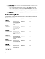
17 Remote Services Profiles.......................................................................................................81
Operating System Deployment Profile....................................................................................................................81
Operating System Deployment Methods.........................................................................................................81
Lifecycle Controller Management Profile...............................................................................................................81
LC Service Methods.........................................................................................................................................82
Auto-discovery Methods..................................................................................................................................82
Export and Import Methods..............................................................................................................................82
Lifecycle Log Methods.....................................................................................................................................83
Hardware Inventory Methods..........................................................................................................................83
Simple NIC Profile...................................................................................................................................................83
Simple NIC Methods........................................................................................................................................83
BIOS and Boot Management Profile......................................................................................................................84
BIOS and Boot Management Methods............................................................................................................85
Persistent Storage Profile.......................................................................................................................................85
vFlash SD Card Methods..................................................................................................................................85
RAID Profile............................................................................................................................................................86
RAID Methods..................................................................................................................................................87
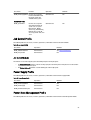
Hardware Inventory Profiles...................................................................................................................................88
Job Control Profile..................................................................................................................................................89
Job Control Methods........................................................................................................................................89
Power Supply Profile..............................................................................................................................................89
Power State Management Profile..........................................................................................................................89
Power State Management Profile Methods....................................................................................................90
Record Log Profile..................................................................................................................................................90
Record Log Profile Methods.............................................................................................................................90
Role Based Authorization Profile............................................................................................................................90
Role Based Authorization Profile Methods......................................................................................................91
Sensors Profile.......................................................................................................................................................91
Service Processor Profile.......................................................................................................................................91
Service Processor Profile Methods.................................................................................................................92
Event Filter Profile...................................................................................................................................................92
Event Filter Profile Methods.............................................................................................................................92
License Management Profile..................................................................................................................................92
License Management Profile Methods............................................................................................................92
iDRAC Card Profile..................................................................................................................................................93
iDRAC Card Profile Methods............................................................................................................................93
Base Server and Physical Asset Profile.................................................................................................................93
Base Server and Physical Asset Profile Methods...........................................................................................94
System Info Profile..................................................................................................................................................94
System Info Methods.......................................................................................................................................94
Simple Identity Management Profile......................................................................................................................94
Simple Identity Methods..................................................................................................................................95
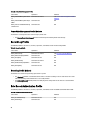
18 Troubleshooting and Frequently Asked Questions............................................................97
Error Messages......................................................................................................................................................97
Auto-discovery LCD Messages..............................................................................................................................97
Frequently Asked Questions...................................................................................................................................98
19 Schema...................................................................................................................................101
Lifecycle Log Schema...........................................................................................................................................101
20 Easy-to-use System Component Names...........................................................................103
8
Introduction
1
The Dell Lifecycle Controller provides advanced embedded systems management. It includes a 1 GB managed and
persistent storage that embeds systems management features in addition to the iDRAC features.
The Dell Lifecycle Controller Remote Services further enable remote systems management in a one-to-many method.
Remote Services is available using Web Service for Management (WS-Management) protocol based Web services
interface for remote server provisioning and management through the iDRAC. The interface is aimed at simplifying many
tasks, some of which include remote operating system (OS) deployment, remote update and inventory, and remotely
automating the setup and configuration of new and already deployed Dell systems.
Remote Services is accessible over the network using the secure Web services interface and can be programmatically
utilized by applications and scripts. Remote services enable management consoles to perform one-to-many bare metal
server provisioning. The combination of the Auto-discovery feature to identify and authenticate the attached Dell system
to the network and integration with one‑to-many management consoles reduces the manual steps required for server
provisioning.
Benefits of Using iDRAC7 With Lifecycle Controller
The benefits include:
•
Increased Availability — Early notification of potential or actual failures that help prevent a server failure or
reduce recovery time after failure.
•
Improved Productivity and Lower Total Cost of Ownership (TCO) — Extending the reach of administrators to
larger numbers of distant servers can make IT staff more productive while driving down operational costs such
as travel.
•
Secure Environment — By providing secure access to remote servers, administrators can perform critical
management functions while maintaining server and network security.
•
Enhanced Embedded Management through Lifecycle Controller – Lifecycle Controller provides deployment and
simplified serviceability through Lifecycle Controller GUI for local deployment and Remote Services (WSManagement) interfaces for remote deployment integrated with Dell OpenManage Essentials and partner
consoles.
For more information on iDRAC7, see Integrated Dell Remote Access Controller User’s Guide available at
support.dell.com/manuals.
Key Features
Remote services enables the Dell Management Console, the Dell Modular Chassis Management Controller, partner
consoles, customer home grown consoles and scripts to remotely perform systems management tasks such as:
•
Install operating systems and drivers
•
Manage Licensing
•
Perform BIOS firmware updates
•
Part replacement management
•
Perform component firmware updates
•
Get hardware inventory information
9
•
Get and set NIC/CNA and RAID configuration
•
Get and set BIOS configuration and BIOS passwords
•
Export lifecycle log
•
Export current and factory shipped hardware inventory log
•
Manage, attach, and boot to vFlash SD card partitions
•
Enable encryption on the controller using local key and lock the virtual disks.
•
Export and import the server profile
•
Schedule and track the status of the update and configuration jobs
Why Use Remote Services?
Remote services offer the following benefits and features:
•
Leverages your existing console for one-to-many server provisioning.
•
Does not utilize operating system resources on the managed system.
•
Provides a secure communication path for management.
•
Reduces manual intervention and improves efficiency while provisioning servers.
•
Allows scheduling configuration changes and updates, thereby reducing maintenance shutdown time.
•
Enables Windows and Linux command line (CLI) scripting.
•
Enables integration to consoles through WS-Management interfaces.
•
Supports OS-agnostic software update.
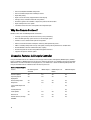
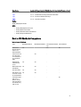
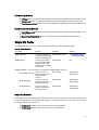
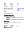
Licensable Features in Lifecycle Controller
Lifecycle Controller features are available based on the type of license (Basic Management, iDRAC7 Express, iDRAC7
Express for Blades, or iDRAC7 Enterprise) you purchase. Only licensed features are available in the Lifecycle Controller
Web interface. For more information on managing licenses, see iDRAC7 User’s Guide. The following table provides the
Lifecycle Controller features available based on the license purchased.
Table 1. Licensable Features
Feature
Base Management
with IPMI
iDRAC7 Express
iDRAC7 Express for
Blades
iDRAC7 Enterprise
Firmware Update
Yes
Yes
Yes
Yes
Operating System
Deployment
Yes
Yes
Yes
Yes
Device Configuration
Yes
Yes
Yes
Yes
Diagnostics
Yes
Yes
Yes
Yes
Server Profile Export and
Import
-
-
-
Yes
Part Replacement
-
-
-
Yes
Local Updates
Yes
Yes
Yes
Yes
Driver Packs
Yes
Yes
Yes
Yes
Yes
Yes
Yes
Remote Services (through
WSMAN
10
Web Services for Management
WS-Management is a Simple Object Access Protocol (SOAP)-based protocol designed for systems management. It is
published by the Distributed Management Task Force (DMTF) and provides an interoperable protocol for devices to
share and exchange data across networks. The Lifecycle Controller Remote Services WS-Management implementation
complies with the DMTF WS-Management specification version 1.0.0.
Dell Lifecycle Controller - Remote Services uses WS-Management to convey DMTF Common Information Model (CIM)based management information; the CIM information defines the semantics and information types that can be
manipulated in a managed system. Dell utilizes the WS-Management interface to allow remote access to the hardware
lifecycle operations.
The Dell-embedded server platform management interfaces are organized into profiles, where each profile defines the
specific interfaces for a particular management domain or area of functionality. Additionally, Dell has defined a number
of model and profile extensions that provide interfaces for additional capabilities. The data and methods available
through WS-Management are provided by the Lifecycle Controller - Remote Services’ instrumentation interface mapped
to the following DMTF profiles and Dell extension profiles:
Standard DMTF
•
•
•
•
•
•
•
•
•
•
•
•
Base Server — Defines CIM classes for representing the host server.
Base Metrics — Defines CIM classes for providing the ability to model and control metrics captured for
managed elements.
Service Processor — Defines CIM classes for modeling service processors.
Physical Asset — Defines CIM classes for representing the physical aspect of the managed elements.
SM CLP Admin Domain — Defines CIM classes for representing CLP’s configuration.
Power State Management — Defines CIM classes for power control operations.
Command Line Protocol Service — Defines CIM classes for representing CLP’s configuration.
Record Log — Defines CIM classes for representing different type of logs.
Role Based Authorization — Defines CIM classes for representing roles.
SMASH Collections — Defines CIM classes for representing CLP’s configuration.
Profile Registration — Defines CIM classes for advertising the profile implementations.
Simple Identity Management — Defines CIM classes for representing identities.
Dell Extensions
•
•
•
•
•
•
Dell OS Deployment — Defines CIM and Dell extension classes for representing the configuration of operating
system deployment features.
Dell Software Update Profile — Defines CIM and Dell extensions for representing the service class and methods
for updating BIOS, component firmware, Lifecycle Controller firmware, Diagnostics, and Driver Pack.
Dell Software Inventory Profile — Defines CIM and Dell Extensions for representing currently installed BIOS,
component firmware, Diagnostics, Lifecycle Controller, and Driver Pack versions. Also provides representation
of versions of BIOS and firmware update images available in Lifecycle Controller for rollback and re-installation.
Dell Job Control Profile — Defines CIM and Dell extensions for managing jobs generated by update requests.
Jobs can be created, deleted, modified and aggregated into job queues to sequence and perform multiple
updates in a single reboot.
Dell Lifecycle Controller Management Profile — Defines CIM and Dell extensions for getting and setting
attributes for managing Auto-Discovery, part replacement, lifecycle log, and hardware inventory export.
Power Supply Profile — Defines the properties and methods related to management of power supplies in a
system.
11
•
SMASH Collections Profile — Defines the collections that support Systems Management - Command Line
Protocol (SM-CLP) target addressing.
•
Dell RAID Profile — Describes the classes, properties and methods for the representation and configuration of
RAID storage.
•
Dell Simple NIC Profile — Describes the classes, properties and methods for the representation and
configuration of the NIC and CNA network controllers.
•
Dell Persistent Storage Profile — Describes the classes, properties and methods to represent and manage the
partitions on the vFlash SD card on Dell platforms.
•
Dell BIOS and Boot Management Profile — Describes the classes, properties, and methods to represent the
configuration of the system BIOS setup and to manage the boot order of the system.
•
Dell CPU Profile — Describes the properties and interfaces for executing systems management tasks related to
the management of processors.
•
Dell Fan Profile — Describes the properties and interfaces for executing systems management tasks related to
the management of fans.
•
Dell iDRAC Card Profile — Describes the properties and interfaces for executing systems management tasks
related to the management of basic properties of iDRAC card.
•
Dell Memory Info Profile — Describes the properties and interfaces for executing systems management tasks
related to the management of memory cards (DIMMs).
•
Dell PCI Device Profile — Describes the properties and interfaces for executing systems management tasks
related to the management of PCI devices in a system.
•
Dell System Info Profile — Describes the properties and interfaces for executing systems management tasks
related to the management of the host system.
•
Dell Video Profile — Describes the properties and interfaces for executing systems management tasks related
to the management of video controllers in a system.
•
Dell License Management Profile — Describes the classes, properties, and methods for managing feature
licenses on the managed systems.
•
Dell Event Filters Profile — Describes the classes, properties, and methods to view the event filters, and set
actions and notifications for the events.
•
Dell Sensors Profile — Describes the classes, properties, and methods to manage the sensors in the managed
system.
•
Dell Power State Management Profile — Describes the classes, properties, and methods to manage the power
in a system.
•
Record Log — Defines CIM classes for representing different type of logs.
The Lifecycle Controller - Remote Services WS-Management implementation uses SSL on port 443 for transport
security, and supports basic authentication. Web services interfaces can be utilized by leveraging client infrastructure
such as Windows WinRM and Powershell CLI, open source utilities such as WSMANCLI, and application programming
environments such as Microsoft .NET.
Other Documents You May Need
In addition to this guide, you can access the following guides available at support.dell.com/manuals. On the Manuals
page, click Software → Systems Management. Click on the appropriate product link on the right-side to access the
documents.
•
•
•
12
iDRAC7 version 1.00.00 Readme provides information on limitations, known issues and resolutions, and so on in
Lifecycle Controller-Remote Services.
Lifecycle Controller Web Services Interface Guide (Windows and Linux) contains the samples to use the various
methods.
The Dell Lifecycle Controller User’s Guide provides information on using the GUI-based pre-operating system
console.
•
The Systems Management Overview Guide provides brief information about the various software available to
perform systems management tasks.
•
The Integrated Dell Remote Access Controller 7 (iDRAC7) User’s Guide provides information about configuring
and using an iDRAC7 for rack, tower, and blade servers to remotely manage and monitor your system and its
shared resources through a network.
•
The Dell Repository Manager User Guide provides information about creating customized bundles and
repositories comprised of Dell Update Packages (DUPs), for systems running supported Microsoft Windows
operating systems.
•
The Lifecycle Controller Supported Dell Systems and Operating Systems section in the Dell Systems Software
Support Matrix provides the list of Dell systems and operating systems that you can deploy on the target
systems.
•
The PERC H710, H710P, and H810 Technical Guidebook for specification and configuration related information
about the PERC H710, H710P, and H810 controllers.
•
The Dell Systems Build and Update Utility (SBUU) User's Guide provides information to deploy and update Dell
systems.
•
The Glossary provides information about the terms used in this document.
The following system documents are available to provide more information:
•
The iDRAC7 Overview and Feature Guide provides information about iDRAC7, its licensable features, and license
upgrade options.
•
The safety instructions that came with your system provide important safety and regulatory information. For
additional regulatory information, see the Regulatory Compliance home page at dell.com/
regulatory_compliance. Warranty information may be included within this document or as a separate document.
•
The Rack Installation Instructions included with your rack solution describe how to install your system into a
rack.
•
The Getting Started Guide provides an overview of system features, setting up your system, and technical
specifications.
•
The Owner’s Manual provides information about system features and describes how to troubleshoot the system
and install or replace system components.
There are additional implementation guides, white papers, profile specifications, class definition (.mof) files, and code
samples you can access in the following locations:
•
Lifecycle Controller page on Dell TechCenter — delltechcenter.com/page/Lifecycle+Controller
•
Lifecycle Controller WS-Management Script Center — delltechcenter.com/page/Scripting+the+Dell+Lifecycle
+Controller
•
MOFs and Profiles — delltechcenter.com/page/DCIM.Library
•
DTMF Web site — dmtf.org/standards/profiles/
•
Lifecycle Controller Web Services Interface Guide–Windows and Linux
Contacting Dell
NOTE: If you do not have an active Internet connection, you can find contact information on your purchase invoice,
packing slip, bill, or Dell product catalog.
Dell provides several online and telephone-based support and service options. Availability varies by country and
product, and some services may not be available in your area. To contact Dell for sales, technical support, or customer
service issues:
1.
Visit support.dell.com.
2.
Select your support category.
13
3.
If you are not a U.S. customer, select your country code at the bottom of the support.dell.com page, or select All to
see more choices.
4.
Select the appropriate service or support link based on your need.
14
Using Remote Services
2
This section describes some of the prerequisites that helps you get started with the Remote Services functionality and
use the new features effectively, for better results.
Common Prerequisites Before Using Remote Services
To successfully perform remote operations on the server, make sure that the following prerequisites are met:
•
Lifecycle Controller 2 version 1.00.00 is installed.
•
iDRAC7 firmware version 1.00.00
•
Latest BIOS version is installed. For more information on the BIOS versions related to the Dell systems, see the
iDRAC7 version 1.00.00 Readme.
•
A WS-Management capable utility is available to perform the tasks.
•
Download the latest Lifecycle Controller Web Services Interface Guide for Windows and Linux. For more
information, see delltechcenter.com/page/Lifecycle+Controller.
•
Collect System Inventory on Restart (CSIOR) is enabled.
Web Services Setup
Make sure that the following conditions are met while setting up the system:
•
Use the following tools to access Remote Services:
–
Windows-based client WinRM that is already installed in the operating system, else you can download it
from support.microsoft.com/kb/968930.
–
Linux-based clients such as the open-source OpenWSMan based CLI. For more information, see
openwsman.org.
–
Java-based client such as open-source project Wiseman. For more information, see
wiseman.dev.java.net.
•
Ensure that you know the IP address of the systems on your network. You will also need to be able to connect to
iDRAC. See the iDRAC documentation at support.dell.com/manuals for more information.
•
Ensure the proper network configuration for client and managed server. Verify the connectivity with the ping
utility. Then ensure that the client and network allows HTTP and SSL protocols.
WinRM Client
Install the WinRM Client on the console to be able to use the Remote Services functionality. Microsoft Windows 7,
Microsoft Windows Vista, and Microsoft Windows Server 2008 contain a standard component called WS-Management.
This component contains the WinRM client. For Microsoft Windows XP and Microsoft Server 2003, you can download
and install this component from support.microsoft.com/kb/968929. You must have local administrator privileges for
installation.
You must configure the client for the connection. For more information, see the Lifecycle Controller Web Services
Interface Guide–Windows version.
15
OpenWSMan Client
The OpenWSMan client is the WS-Management CLI that is part of the open-source project Openwsman. To download,
build, install, and use the WS-Management CLI and OpenWSMan packages from sourceforge.net, see openwsman.org
for download links.
NOTE: You must configure the client for the connection. For configuration details, see the Lifecycle Controller Web
Services Interface Guide–Linux version.
Using Use Cases
Use Cases Structure
The following use cases are available for reference:
•
Prerequisites — Lists the prior conditions before executing the scenario.
•
Feature description — Describes the scenario and provides a brief description about the features.
•
Important — Lists any special conditions while executing the scenario.
•
Feature or System Behavior — Lists the functioning of the feature and system responses.
•
Post-requisites — Lists the post-execution tasks to be performed by the user or those performed by the system.
•
References — Provides the location in the Lifecycle Controller Web Services Interface Guide–Windows and
Linux where you can find detailed information for executing the steps.
How to Read Use Cases?
•
Read and understand the scenario.
•
Set up the required infrastructure and complete all the pre-requisite tasks.
•
Adhere to any special conditions.
•
Understand how the feature functions and system responses.
•
Execute the steps using the reference table that has location of the task details in the Lifecycle Controller Web
Services Interface Guide–Windows and Linux versions along with the additional information such as methods,
class, input parameters, and output parameters that can be found in the profile document and MOF file.
Use Case Scenarios
16
•
Exporting Server Profile to iDRAC vFlash Card or Network Share
•
Importing Server Profile From a iDRAC vFlash Card or a Network Share
•
Configuring RAID
•
Changing the Personality and Bandwidth of a Partition for a CNA
•
Setting the Virtual Address Attributes
•
Setting the Boot Target-ISCSI and FCoE
•
Getting and Setting the iDRAC Attributes
•
Getting and Setting iDRAC Users and Roles
•
Reporting iDRAC IP Address Change
•
Setting Modifying and Deleting BIOS Password
•
Retrieving Remote Service Status
Auto-discovery and Handshake
3
The Auto-discovery feature in iDRAC allows newly installed servers to automatically discover the remote management
console that hosts the Provisioning Server. The Provisioning Server provides custom administrative user credentials to
the iDRAC so that the management console can discover and manage the newly installed managed system.
If you ordered a Dell system with the Auto-discovery feature Enabled (factory default setting is Disabled), then the
iDRAC is delivered with DHCP-enabled and disabled user accounts. If the auto-discovery feature is set to Disabled, you
can manually enable this feature and disable the default administrative account using the iDRAC7 Settings utility. For
more information on Auto-discovery, see the Lifecycle Controller Management Profile.
Using WS-Management, you can invoke the SetAttribute() method on the DCIM_LCService class to set the
provisioning server IP address property. For more information on using the SetAttribute() invocations, see the
DCIM_LCManagement profile or the Lifecycle Controller Interface Guide (Windows and Linux) available at
delltechcenter.com/page/Lifecycle+Controller.
To successfully perform remote operations on the server, make sure that the following are met:
•
Common Prerequisites Before Using Remote Services
•
Dell Deployment Pack is installed on the provisioning server.
•
Collect System Inventory on Restart (CSIOR) is enabled.
Configuring iDRAC for Auto-discovery
To manually enable the Auto-discovery feature:
1.
Install the system at the desired location.
2.
Turn on the managed system.
3.
Press <F2> during startup.
The System Setup Main Menu page is displayed.
4.
Click iDRAC Settings.
The iDRAC Settings page is displayed.
5.
Specify the following settings:
–
Network Settings — Set Enable NIC to Enabled (for Blade servers only).
–
Common Settings — Set Auto Config Domain Name to Enabled.
–
IPv4 Settings — Set Enable IPv4 to Enabled.
NOTE: Even though the infrastructure supports IPv6, it is disabled during auto-discovery. It can be enabled after
provisioning the server.
6.
– DHCP — Set Enable DHCP to Enabled and set Use DHCP to obtain DNS Server Addresses to Enabled.
Click Back, and click User Configuration.
The User Configuration page is displayed.
7.
Select Disabled under Enable User.
This disables the default administrative account.
8.
Click Back, and click Remote Enablement.
17
The Remote Enablement page is displayed.
9.
Under Enable Auto-Discovery, select Auto-Discovery.
NOTE: You must disable administrator account to activate Auto-discovery feature.
10. In the Provisioning Server box, enter the provisioning server IP address or host name string. The following
conditions apply while using a command to set the provisioning server IP address or hostname:
–
When issuing the racadm racresetcfg or updating iDRAC7, make sure to enable the Preserve
Configuration option while resetting the iDRAC7 to defaults. If this option is disabled, the provisioning
server IP or hostname is erased.
–
Auto-discovery feature does not use the newly set provisioning server IP address or hostname for any
handshakes in progress, but is used only during the next handshake process.
11. Click Back and then click Finish.
12. Click Yes to save the changes. Press <Esc> to exit System Setup.
Provisioning Server String Format
Auto-discovery feature supports setting multiple IP addresses and/or host names using the following format:
•
The string is a list of IP addresses and/or host names and ports separated by comma.
•
Host name is qualified.
•
IPv4 address starts with ‘(‘ and ends with ‘)’ when specified at the same time with a hostname.
•
Each IP address or hostname can be optionally followed by a ‘:’ and a port number.
•
Examples of valid strings are - hostname, hostname.domain.com.
Setting Provisioning at Required Location
To set the provisioning at the required location:
1.
Turn on the managed system.
2.
Press <F10> Lifecycle Controller during startup.
The Lifecycle Controller page is displayed.
3.
Navigate to System Setup → Advanced Configuration → iDRAC Settings .
4.
Click Next to navigate to the following pages and specify various settings:
–
Network Settings — Set Enable NIC to Enabled (for blade servers only).
–
Common Settings — Set Auto Config Domain Name to Enabled.
–
IPv4 Settings — Set Enable IPv4 to Enabled.
NOTE: Even though the infrastructure supports IPv6, it is disabled during Auto-discovery and it can be enabled
after provisioning the server.
–
DHCP — Set Enable DHCP to Enabled and set Use DHCP to obtain DNS Server Addresses to Enabled.
5.
On the last page, click Apply.
6.
Click Finish.
7.
Click Exit and Reboot.
Auto-discovering Managed System
To auto-discover the managed system:
18
1.
Connect the system to the network.
2.
Turn on the managed system.
The system performs the following operations:
–
iDRAC starts, acquires the Provisioning Server IP addresses or host names from DHCP/DNS and
announces itself to the Provisioning Server.
–
The Provisioning Server validates and accepts the secure handshake session from the iDRAC.
–
The Provisioning Server provides custom user credentials with administrator privileges to iDRAC.
–
iDRAC receives and completes the secure handshake.
After the managed system is discovered, iDRAC can be managed through its newly acquired credentials to perform
operations such as remote operating system deployment and systems management tasks.
Configuring DHCP or DNS
Before adding the system to the network and enabling the Auto-discovery feature, make sure that the Dynamic Host
Configuration Protocol (DHCP) server or Domain Name System (DNS) are configured. If the Provisioning Server IP
address or host name is not provided through a WS-Management command, or using F2 or F10 based Provisioning
Server inputs, use one of the following DHCP or DNS based methods to configure DHCP or DNS so that iDRAC can
discover the domain name or address of the provisioning server:
•
The DHCP server provides a comma separated list of Provisioning Server locations using a Vendor Scope Option
43 of Class, LifecycleController, Option 1. These locations can be a hostname or IP address, and optionally
include a port. The iDRAC resolves the hostname of the management console to an IP address with a DNS
lookup.
•
The DNS server specifies a service option _dcimprovsrv._tcp that resolves to an IP address.
•
The DNS server specifies the Auto-discovery default "Host A" Record named DCIMCredentialServer,
resolving to the IP Address of the Provisioning Server.
For more information on configuring DHCP and DNS, see Lifecycle Controller Auto Discovery Network Setup
Specification on the Dell Enterprise Technology Center at delltechcenter.com/page/Lifecycle+Controller.
Viewing the Discovery Status on the Front Panel Display
You can view the status of the discovery and handshake progress on the front panel display:
NOTE: The front panel display is available only on Rack and Tower servers. For Blade servers, you must view the
front panel display on CMC.
•
Running
•
Stopped
•
Suspended
•
Complete
If the auto-discovery process is running, you can view its progress code that corresponds to how far the last attempt
reached (that is whether discovery and handshake is blocked because the NIC is disabled, or an administrator account
is enabled, and so on). You can also view the time remaining before time-out.
Reinitiating Auto-discovery in New Environments
You can reinitiate Auto-discovery using Remote Services, even though the system has previously completed Autodiscovery. Use the following options to reinitiate:
19
•
Whether Auto-discovery runs immediately or after the next AC power cycle. This is a required input.
•
Provisioning Server IP address or host name. This is optional.
For example, you must reinitiate Auto-discovery to move the managed system from one data center to another. The
auto-discovery settings are persisted along with the credentials used for discovery. When the system is turned on in the
new data center, Auto-discovery runs according to the factory default settings, and creates the new iDRAC user
credentials for the new data center.
NOTE: iDRAC administrator or iDRAC user with Execute Server Command privilege is required to run WSManagement commands.
The following operations are performed by default while reinitiating Auto-discovery:
20
•
Enable NIC (Blade servers)
•
Enable IPv4
•
DHCP enable
•
Deletes all administrator accounts except User ID 2, which is the default ’root’ administrator account.
•
Disable Active Directory
•
Get DNS server address from DHCP
•
Get DNS domain name from DHCP
Managing Licenses
4
You can manage the licenses to enable or disable the various systems management features. Using Remote Services,
you can:
•
Get a list of installed licenses
•
Get a list of licensable devices
•
Install or delete a license
•
Export the license
Displaying Installed Licenses
•
Perform the Enumerate operation on the DCIM_License class to display the instance properties of all the
Licenses installed on the system.
•
Perform the Get operation on the DCIM_License class using the correct instance ID of the required license
to display the related properties.
Displaying Licensable Devices
•
Perform the Enumerate operation on the DCIM_LicensableDevice class to display the instance properties
of all the licensable devices installed on the system.
•
Perform the Get operation on the DCIM_LicensableDevice class using the correct instance ID of the
required licensable device to display the related properties.
Installing a License
To successfully perform remote operations on the server, make sure that the following prerequisites are met.
•
Common Prerequisites Before Using Remote Services
•
If you are using a network share, set up a CIFS or NFS share and copy the license to the network share.
To install a license:
1.
Enumerate DCIM_LicensableDevice class to view the available licensable devices. Note down the FQDD of
the licensable device on which the license is installed.
2.
See the LicenseList property to verify that licenses are not currently installed on the licensable device. The
LicenseList property displays the list of Entitlements IDs of licenses currently installed on the device. If there are
licenses installed, delete the licenses using the DeleteLicense() method using the Entitlement ID of the license as
the input parameter. Alternatively, use the FQDD of the licensable device as the input parameter to delete all
licenses installed on that device.
3.
You can use either the ImportLicense() method or the ImportLicenseFromNetworkShare() method.
4.
Install using ImportLicense() method:
–
Base64 encode the license file.
–
Use the encoded license file and the FQDD of the licensable device to prepare the input parameters.
21
– Invoke the ImportLicense() method.
Install using ImportLicenseFromNetworkShare() method:
5.
–
Use the network share parameters and the licensable device FQDD to prepare the input parameters.
–
Invoke the ImportLicenseFromNetworkShare() method.
–
Perform the Get operation on DCIM_LifecycleJob class using the returned job ID as the instance ID
to view the status of the import license job.
References For Installing a License
You can see the following documents for more information:
•
Profile — Dell_LicenseManagement Profile
•
MOFs
–
DCIM_LicensableDevice.mof
–
DCIM_License.mof
–
DCIM_LicenseManagementService.mof
–
DCIM_LCElementConformsToProfile.mof
–
DCIM_LCRegisteredProfile.mof
For more information, see:
•
Common Prerequisites Before Using Remote Services
•
Licensable Features in Lifecycle Controller
Replacing a License
To replace a license:
1.
Enumerate the DCIM_LicensableDevice class to get the FQDD of the licensable device.
2.
View the LicenseList property and note down the Entitlement ID of the license being replaced.
3.
Base64 encode the new license file.
4.
Using the encoded license file, the licensable device FQDD and the Entitlement ID of the old license are use to
prepare the input parameters.
5.
Invoke the ReplaceLicense() method to replace a license.
Deleting a License
A single license can be deleted using the Entitlement ID of the license and invoking the DeleteLicense() method.
Alternatively, all licenses can be deleted from a licensable device using the FQDD of the licensable device and invoking
the DeleteLicense() method.
Exporting a License
You can export the licenses using one of the four export methods:
22
•
ExportLicense() — This method exports a single license specified by Entitlement ID. The license is an output
parameter of the method and is base64 encoded.
•
ExportLicenseToNetworkShare() — This method exports a single license specified by Entitlement ID to an NFS
or CIFS network share.
•
ExportLicenseByDevice() — This method exports all licenses installed on a licensable device. The licenses are
an output parameter of the method and are base64 encoded.
•
ExportLicenseByDeviceToNetworkShare() — This method exports all the licenses installed on a licensable
device to an NFS or CIFS network share.
NOTE: If multiple licenses are exported from a single licensable device, the file names are suffixed with a _0.xml,
_1.xml, _2.xml, and so on.
23
24
Managing Certificates
5
Use the certificate management feature to transfer custom-defined certificates to iDRAC7 and create a unique
certificate based on the service tag of a system to enhance the security. While placing the order, you can request Dell to
factory preset the system with the certificate of your choice using the Custom Factory Install (CFI) process available
from Dell.
Creating Custom Trusted Root Client Certificates for the
Provisioning Server
The DownloadClientCerts() method on DCIM_LCService class can be called to generate a custom signed Autodiscovery client certificate. The method uses a Certificate Authority generated key certificate and related hash and
password parameters as input. The key certificate provided is used to sign a certificate containing the system service
tag as the Common Name (CN). The method returns a job ID that can be used to check the success of the download,
generation, and installation of the Auto-discovery client certificate. For examples of command line invocations using
WinRM and WSMANCLI, see the Lifecycle Controller Web Services Interface Guide–Windows and Linux version.
Providing Custom Server Certificates
The DownloadServerPublicKey() method on the DCIM_LCService class can be called to transfer the CA certificate
that is used to sign all the provisioning servers in the deployment network.
NOTE: The trusted CA certificate is used to authenticate all the provisioning servers.
Make sure that the Provisioning Server Certificate is self-signed before using it on iDRAC.
The method uses the CA certificate and related hash and hash type parameters as input. The method returns a job ID
that can be used to check the success of the processing and installation of the Provisioning Server public key. For
examples of command line invocations using WS-Management utilities, see the Lifecycle Controller Web Services
Interface Guide–Windows and Linux version. DCIM Profile specification and related MOF files are available at
delltechcenter.com/page/DCIM.Library.
Deleting Custom Certificates
You can delete any of the custom certificates that are uploaded on the managed system or created on it. Using this
feature, you can wipe all the custom signed certificates from the server, whenever required.
NOTE: This feature does not delete the factory certificates.
Custom Server Public Key Deletion
Use the DeleteAutoDiscoveryServerPublicKey() method on the DCIM_LCService class to delete the CA certificate
that is used to validate or authenticate server certificates.
25
Custom Client Certificate Deletion
Use the DeleteAutoDiscoveryClientCerts() method on the DCIM_LCService class to delete a client certificate and
private key.
Changing the Web Server or WS-Management Encryption Certificate and Private Key
from PKCS #12
To change the certificate and key:
1.
Generate a CSR and private key. The CSR needs to be signed by a CA.
2.
Combine the certificate with the private key then encrypt it into a PKCS#12 file.
3.
BASE64 encode the PKCS#12 file to convert it from binary to text so you can pass it as a WS-Management
parameter.
4.
Copy the contents of the active certificate to an XML file.
Managing Server Certificates
To successfully perform remote operations on the server, make sure that the following prerequisites are met:
•
Common Prerequisites Before Using Remote Services
•
Time is set correctly on iDRAC.
The certificate on some systems have expired and has to be newly uploaded. The certificate authenticates Web GUI,
WS-Management, RACADM, Active Directory, and LDAP sessions.
To manage server certificates:
NOTE: The method restarts all Web services and closes all active sessions.
NOTE: The CA that signed the new server certificate must be added to the trusted Root CA list on all clients.
1.
Create a CSR and private key (without password protection) — openssl req -new -nodes.
2.
Either sign the CSR using ’openssl ca’ or upload to a signing web server.
3.
Copy the certificate and private key into a file (PEM file) — cat cert.pem key.txt > cert_key.pem.
4.
Convert cert_key.pem to pkcs12 — openssl pkcs12 -export -in cert_key.pem -passin file:password.txt -out new.pfx
5.
Encode the pkcs12 base64 file — openssl base64 -export -in new.pfx -out new_pfx.txt.
6.
Use the contents of new_pfx.txt as a parameter to the WS-Management command.
7.
Invoke SetCertificateAndPrivateKey() method with the required parameters.
After setting the server certificate the Web services restarts. All sessions are closed and new WS-Management
commands must accept the new server certificate.
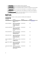
References For Managing Server Certificates
NOTE: The sections referenced in this table contain only generic examples.
26
Table 2. Step Number and Location
Step Number
Location in Lifecycle Controller Web Services Interface Guide (Windows or
Linux)
-
12.10 — Set iDRAC Certificate and Private Key
Profiles
DCIM_LCManagement Profile
MOFs
DCIM_LCService.mof
Managing Directory CA Certificate
Need to upload the trusted root CA certificate to authenticate Active Directory or LDAP sessions.
To successfully perform remote operations on the server, make sure that the following prerequisites are met:
•
Common Prerequisites Before Using Remote Services
•
Time is set correctly on iDRAC.
To manage the directory CA certificate:
NOTE: The method restarts all web services and closes all active sessions.
1.
Download the CA certificate from the LDAP or AD server.
2.
Use openssl or another tool to encode it in the base64 format.
3.
Invoke SetPublicCertificate() method with the required parameters.
After setting the server certificate the web services restarts. All sessions are closed and new WS-Management
commands must accept the new server certificate.
References For Managing Directory CA Certificate
NOTE: The sections referenced in this table contain only generic examples.
Table 3. Step Number and Location
Step Number
Location in Lifecycle Controller Web Services Interface Guide (Windows or Linux)
-
12.9 — Set Public Certificates
Profiles
DCIM_LCService
MOFs
DCIM_LCService.mof
27
28
Deploying the Operating System
6
The operating system deployment capabilities enable deployment of an operating system remotely using WSManagement web services protocols and CIFS and NFS network file sharing protocols. Detailed interface specifications
and class definition (.mof) files at the Lifecycle Controller section on the Dell Enterprise Technology Center at
delltechcenter.com. The following features are available in the form of extrinsic methods that can be used in various
combinations depending on use cases to perform end-to-end OS deployment on the server:
•
Remotely activate the local exposure of embedded drivers for the selected operating system as an emulated
USB device to the server that is automatically installed during installation.
•
Remotely acquire embedded drivers per selected operating system to a CIFS or NFS network share that can be
used later for operating system deployment.
•
Boot to an ISO image located on a network share to initiate an operating system installation.
•
Download ISO to vFlash SD card and boot from the card to initiate an operating system installation.
•
Connecting an ISO from network, attaching it as virtual USB CD-ROM device to the server and boot the server to
the ISO every time the server reboots.
•
One time boot to PXE.
•
One time boot to hard disk.
For more information, see Operating System Deployment Profile
Deploying Operating System
To successfully perform remote operations on the server, make sure that the following prerequisites are met:
•
Common Prerequisites Before Using Remote Services
•
Boot disk is available on the server to install operating system.
•
It is recommended that the latest driver pack is installed so that drivers for newer operating systems and newer
devices are available.
•
Provisioning console, application or appropriate scripts that are capable of sending WS-Management Web
services requests and method invocations.
Install an operating system using the drivers that are attached locally on the server through Lifecycle Controller.
To perform remote operating system deployment:
NOTE: To use a custom operating system, create the custom operating system image (.iso format) and share it on
the network or create ISO image on a DVD.
1.
Invoke the GetDriverPackInfo() method to list the supported operating systems supported on the server and the
driver pack version installed on Lifecycle Controller.
2.
Invoke the UnpackAndAttach() method to copy the drivers for the selected operating system from Lifecycle
Controller to an internal USB-based drive labeled OEMDRV that is attached to the server.
By default this OEMDRV drive is exposed to the server for approximately 18 hours, and after that it is detached
automatically. However, use the optional parameter ExposeDuration while invoking the method to specify the
duration (between 1 minute and 18 hours) for which the drive must be present on the server.
29
3.
Depending on where the operating system image is hosted, use one of the following methods to attach the ISO to
the local server and reboot to it immediately.
–
BootToNetworkISO() — If the operating system image (.iso format) is hosted in a network share (NFS or
CIFS), use this method to attach the network ISO as virtual USB CD-ROM device to the server and
immediately boot to it to start the operating system installation.
–
BootToISOFromVFlash() — If the operating system image (.iso format) is hosted in the vFlash SD card, use
this method to attach the image as local USB CD-ROM device and immediately boot to it to start the
operating system installation.
NOTE: You must use the DownloadISOToVFlash() method as a prerequisite before executing
BootToISOFromVFlash() to copy the .iso image from NFS, CIFS, or TFTP share to vFlash so that it can be used later
to boot. However, if the vFlash SD card is installed and not formatted, this method formats the card and then
downloads the ISO image.
–
4.
5.
BootToPXE() — If the operating system image is hosted in PXE then use this method to reboot the server
and boot to PXE to initiate OS install
After the OS installation is complete, use one of the methods based on how ISO was attached to detach the ISO
from host server.
–
DetachISOImage() — If the ISO was attached using BootToNetworkISO(), use this method to detach the
ISO from host server.
–
DetachISOFromVFlash() — If ISO was attached using BootToISOFromVFlash() then use this method to
detach ISO from host server. DeleteISOFromVFlash() method can be used after that to delete the ISO from
vFlash if the ISO is no longer required.
Invoke DetachDrivers() method to detach OEMDRV drive that contains the operating system drivers.
NOTE: During OS installation, the native OS installer automatically installs the drivers present in OEMDRV device.
References For Deploying Operating System
NOTE: The sections referenced in this table contain only generic examples.
Table 4. Step Number and Location
Step Number
Location in Lifecycle Controller Web Services Interface Guide (Windows or Linux)
step 1
11.3.1 — Get Driver Pack Information
step 2
11.3.2 — Unpack Selected Drivers and Attach to Host OS as USB Device
step 3
11.3.6 — Boot to Network ISO
11.3.11 — Boot to ISO from VFlash
11.3.8 — Boot To PXE
step 4
11.3.7 — Detach Network ISO USB Device
11.3.13 — Detach ISO from VFlash
step 5
11.3.3 — Detach Emulated USB Device Containing Drivers
Profiles
DCIM_OSDeployment Profile
MOFs
•
•
•
30
DCIM_OSDeploymentService.mof
DCIM_OSDConcreteJob.mof
DCIM_LCElementConformsToProfile.mof
Step Number
•
Location in Lifecycle Controller Web Services Interface Guide (Windows or Linux)
DCIM_LCRegisteredProfile.mof
Copying OS Drivers to Network Share
To copy the operating system drivers from Lifecycle Controller to a network share:
1.
Invoke the GetDriverPackInfo() method to list the supported operating systems on the server and the Driver Pack
version installed on Lifecycle Controller.
2.
Invoke the UnpackAndShare() method to copy the drivers for the selected operating system from Lifecycle
Controller to a network share (CIFS or NFS.)
References For Deploying Operating System
NOTE: The sections referenced in this table contain only generic examples.
Table 5. Step Number and Location
Step Number
Location in Lifecycle Controller Web Services Interface Guide (Windows or Linux)
step 1
11.3.1 — Get Driver Pack Information
step 2
11.3.2 — Unpack Selected Drivers and Attach to Host OS as USB Device
Profiles
DCIM_OSDeployment Profile
MOFs
•
•
•
•
DCIM_OSDeploymentService.mof
DCIM_OSDConcreteJob.mof
DCIM_LCElementConformsToProfile.mof
DCIM_LCRegisteredProfile.mof
Using Remote File Share
To successfully perform remote operations on the server, make sure that the prerequisites provided in the Common
Prerequisites Before Using Remote Services are met.
To deploy the operating system using remote file share:
1.
Invoke the ConnectRFSISOImage() method that connect the ISO on the the Remote File Share (RFS) that is emulated
as a local CD-ROM device to the server. Make sure that RFS is attached using iDRAC GUI, RACADM, or set the
iDRAC attribute AttachMode value to Attach through Web services.
2.
Invoke the GetRFSISOImageConnectionInfo() method to get the RFS connection information.
3.
Invoke the DisconnectRFSISOImage() method to disconnect the ISO image from the server.
References For Using Remote File Share
NOTE: The sections referenced in this table contain only generic examples.
31
Table 6. Step Number and Location
Step Number
Location in Lifecycle Controller Web Services Interface Guide (Windows or Linux)
step 1
11.3.18 - Connect RFS ISO Image
step 2
11.3.20 - Get RFS ISO Image Connection Information
step 3
11.3.19 - Disconnect RFS ISO Image
Profiles
DCIM_OSDeployment Profile
MOFs
•
•
•
•
DCIM_OSDeploymentService.mof
DCIM_OSDConcreteJob.mof
DCIM_LCElementConformsToProfile.mof
DCIM_LCRegisteredProfile.mof
Booting to ISO During Server Maintenance
To successfully perform remote operations on the server, make sure that the prerequisites provided in the Common
Prerequisites Before Using Remote Services section are met.
In data centers and enterprise environments normally physical servers are used to host virtual machines and work
loads. When the server requires maintenance (hardware replacement, configuration changes, updates, and so on), the
workloads are migrated to other physical systems and the original server goes to maintenance mode. In this mode, the
server boots to a pre-OS environment (usually an ISO) that is attached from network share multiple times until all the
issues are resolved. Using OS Deployment profile, the following methods can be used to achieve this more efficiently.
To boot to ISO during server maintenance:
1.
Invoke the ConnectNetworkISOImage() method to expose the ISO from a network share (CIFS or NFS) as a virtual
CD-ROM device to the server. Whenever the managed system is rebooted during maintenance, the system boots to
this ISO irrespective of the boot order each time, until the ISO is detached using the DisconnectNetworkISOImage()
method.
NOTE: The ISO is re-attached when iDRAC resets or if there is a power disconnection.
2.
Invoke the GetNetworkISOImageConnectionInfo() method to retrieve the details regarding the network ISO that is
attached using ConnectNetworkISOImage() method. It also indicates whether the ISO is booted from the system or
not. For more information, see OSDeployment profile and the related MOFs.
3.
Invoke the DisconnectNetworkISOImage() method to detach the ISO image from the server.
4.
Invoke the SkipISOImageBoot() method so that the system does not boot once to the ISO attached (using the
ConnectNetworkISOImage() method) during the next server boot. For subsequent server reboots, BIOS continues to
boot to the ISO until the DisconnectNetworkISOImage() method is run to detach the ISO.
References For Booting to ISO During Server Maintenance
NOTE: The sections referenced in this table contain only generic examples.
Table 7. Step Number and Location
Step Number
Location in Lifecycle Controller Web Services Interface Guide (Windows or Linux)
step 1
11.3.14 — Connect Network ISO Image
32
Step Number
Location in Lifecycle Controller Web Services Interface Guide (Windows or Linux)
11.3.15 — Disconnect Network ISO Image
step 2
11.3.17 — Get Network ISO Image Connection Information
step 3
11.3.15 — Disconnect Network ISO Image
step 4
11.3.16 — Skip ISO Image Boot
Profiles
DCIM_OSDeployment Profile
MOFs
•
•
•
•
DCIM_OSDeploymentService.mof
DCIM_OSDConcreteJob.mof
DCIM_LCElementConformsToProfile.mof
DCIM_LCRegisteredProfile.mof
Boot to ISO Methods Comparison
Table 8. . Boot to ISO Methods
Steps
BootToNetworkISO
BootToISOFromVFlash ConnectNetworkISOIm ConnectRFSISO
age
Connect to a
Network ISO and
attach it as a
Virtual CD-ROM
Yes
-
Yes
Yes
Connect to an ISO
on a vFlash SD
card and attach it
as a Virtual CDROM
-
Yes
-
-
Automatically
reboot the host
server
Yes
Yes
-
-
Boot to ISO image
immediately
Yes
Yes
-
-
One-time reboot
Yes
Yes
-
-
Attached to a host Yes
server for 18 hours
(or specified time)
Yes
-
-
Can perform other
jobs such as
updates, config
after execution of
this method using
web services
-
-
Yes
-
33
Steps
BootToNetworkISO
NOTE: Subsequent
host reboot does
not automatically
boot to the ISO
Image unless the
device (ISOIMG) is
set as the first
device in BIOS
boot list. This is
applicable only
when the ISO is
attached and the
time has not
expired or ISO is
not detached
explicitly.
BootToISOFromVFlash ConnectNetworkISOIm ConnectRFSISO
age
NOTE: Whenever
the host system
reboots, BIOS will
boot to this device
(ISOIMG)
irrespective of its
boot order.
NOTE: If RFS
device is the first
device in BIOS
boot list and if the
server reboots,
BIOS boots to the
attached ISO each
time.
One Time Boot
Use the One-time-boot methods to immediately reboot the server and then boot to the ISO, Hard Disk, or PXE. Use these
methods to do a one-time boot to a pre-boot ISO while performing server maintenance, initiating an operating system
installation, booting to the hard disk, or booting to PXE.
To do this:
•
•
BootToPXE() — Invoke this method to reboot the server immediately and to boot to the PXE irrespective of the
boot order in boot list.
BootToHD() — Invoke this method to reboot the server immediately and boot to the first hard disk on the server
irrespective of the boot order in boot list.
NOTE: Alternatively, use BIOS methods such as ChangeBootOrderByInstanceID() or SetAttribute() for one time
boot.
BootToHD Method Behavior
Following are the some of the instances where the method may not work correctly:
•
•
•
•
If the system has more than one hard drive, it selects the first hard drive in the boot order.
If the boot order has a different device as the first device (for example, USB flash drive), it boots to this device.
If the system is in UEFI boot mode, the hard disk with the operating system must be installed in UEFI boot mode
also. One time boot to the hard disk with the operating system installed in BIOS boot mode does not work.
If the system has no hard disk installed, the method still runs. Therefore, make sure a supported hard disk is
installed before running the method.
About Job Identifiers
Several methods described in this document return job identifiers as output parameters. The jobs help to track a
requested action that cannot be performed immediately and, because of underlying technology constraints, takes longer
than standard Web service request response timeouts. The returned job identifier can subsequently be used in WSMAN Enumerate or Get requests to retrieve job object instances. Job object instances contain a job status property that
can be checked to see what state the job is in and whether it completed successfully or encountered a problem and
34
failed. If a job failure occurs, the job instance also contains an error message property that provides detailed information
on the nature of the failure. Other properties contain other error identification information that can be used to localize
the error message to the supported languages and get more detailed error descriptions and recommended response
action descriptions.
All the DCIM_OSDeploymentService related methods described in this document return error codes indicating
whether the method was successfully executed, an error occurred, or a job was created. Job creation occurs if the
action being performed in the method cannot be completed immediately. Additionally, if an error occurs, the methods
also returns output parameters that include an error message (in English) and other error identifiers that can be used to
localize the error to the supported languages. The error identifiers can be used to index into and process Dell Message
Registry XML files. The Dell Message Registry files are available in the six supported languages, one file per language.
In addition to translated error messages, the Message Registry files contain additional detailed error descriptions and
recommended response actions for each error returned by the Lifecycle Controller Remote Services web service
interface. To download the Dell Message Registry XML files, see delltechcenter.com/page/Lifecycle+Controller/.
The methods that return concrete job instances are:
•
UnpackAndAttach()
•
UnpackAndShare()
•
BootToNetworkISO()
•
DownloadISOToVFlash()
•
BootToISOFromVFlash()
•
ConnectNetworkISOImage()
•
ConnectRFSISOImage()
The methods that return only output parameters and no job instances are:
•
GetDriverPackInfo()
•
DetachDrivers()
•
DetachISOImage()
•
BootToPXE()
•
BootToHD()
•
GetHostMACInfo()
•
DetachISOFromVFlash()
•
DeleteISOFromVFlash()
•
DisconnectNetworkISOImage()
•
GetNetworkISOImageConnectionInfo()
•
SkipISOImageBoot()
•
DisconnectRFSISOImage()
•
GetRFSISOImageConnectionInfo()
35
36
7
Managing Jobs
Remote Services provides the following functionalities to manage Lifecycle Controller jobs:
•
Creating Jobs — Create specific types of jobs to apply configurations.
•
Scheduling Jobs and Job Queues — Run multiple jobs in a single reboot of the system using the
SetupJobQueue() method on the DCIM_JobService class. If you create a job using the
CreateTargetedConfigJob() method without setting the start time, use the SetupJobQueue() method to set the
schedule and order of execution. If the start time was set in the CreateTargetedConfigJob() method, it cannot be
bundled with the other jobs, and the job is setup for execution at the time that was specified.
•
Deleting Jobs — Delete a specified existing job using the DeleteJobQueue() method on the
DCIM_JobService class.
•
Reporting all Jobs — Enumerate the DCIM_LifecycleJob class to report all the jobs.
•
Reporting scheduled Jobs — Enumerate the DCIM_LifecycleJob class with a selection filter of
JobStatus=Scheduled to generate a report of all the scheduled jobs.
For more information on job control, see the Job Control Profile.
Job Types
There are two types of jobs, system created jobs (implicit) and user created jobs (explicit):
•
System created jobs are created when you run specific Remote Services tasks. For example, Remote Services
features such as export hardware inventory, export license, create persistent storage partition, and so on create
a job and return the job ID. Polling the job status determines the completion status of the task.
•
User created jobs such as CreateTargetedConfigJob, CreateRebootJob, and InstallFromURI are used to apply
user configurations for RAID, NIC, BIOS, and so on. They can be scheduled to run immediately or at a scheduled
time.
System Created Jobs
User Created Jobs
vFlash (Initialize)
RAID configuration
vFlash (Create Partition)
BIOS configuration
vFlash (Format Partition)
NIC configuration
vFlash (Attach Partition)
iDRAC configuration
vFlash (Detach Partition)
System configuration
vFlash (Export Data from Partition)
Software Update of (BIOS, NIC, RAID, and so on)
vFlash (Create Partition using Image)
Reboot
Export Lifecycle log
Export Hardware Inventory
Export Factory Configuration
37
User Created Jobs
The following are the user created jobs:
•
•
•
CreateTargetedConfigJob — This method is used while configuring RAID, NIC, BIOS, iDRAC, and System. Use
this method to commit the configuration changes and create a job to apply the configuration changes.
CreateRebootJob — This method is used to create reboot jobs.
InstallFromURI — This method is used to update the firmware for BIOS, RAID, NIC, iDRAC, PSU, Lifecycle
Controller, OS driver packs, and Diagnostics. On success, this method returns a job ID. This job ID runs the
software update on that entity.
NOTE: If the InstallFromURI() method is used to update the BIOS, RAID, NIC, iDRAC, and PSU firmware, use the
SetupJobQueue() method to schedule the job ID.
NOTE: If the InstallFromURI() method is used to update the Lifecycle Controller, driver pack, and Diagnostics, do
not schedule a job.
Job Scheduling
The jobs can be scheduled for job IDs that are returned using one of the job creation methods.
SetupJobQueue — This method is used only with those job IDs that are returned by one of the job creation methods and
are not already scheduled.
Job Deletion
Using the JID_CLEARALL() method, all the current jobs in a system can be deleted. Alternatively, delete a specific job
using its job ID.
Scheduling Separate Jobs for Multiple Actions
To schedule separate jobs for multiple actions (in the following example, BIOS and NIC/CNA update and NIC
configuration):
1.
Invoke the InstallFromURI() method for the BIOS and NIC firmware update packages.
The method downloads the BIOS and NIC updates, and creates a job ID for each device update job.
2.
Set the NIC attributes for a NIC (for example, Integrated NIC 1) and create a targeted job for this set. The method
returns a job ID.
3.
Take these job IDs and use the SetupJobQueue() method to schedule these jobs so that they are executed in the
order specified at the specified start time.
NOTE: For iDRAC to automatically reboot the system at the scheduled time, create a reboot job (specifying the type
of reboot — graceful or power cycle) and include the reboot job ID in the list of jobs specified in the
SetupJobQueue() method invocation. If a reboot job is not included in the Job Queue setup, the jobs are ready to
run at the scheduled start time but rely on an external action to restart the system and start the job execution.
Running Multiple Target Jobs
To run multiple target jobs (for example, setting NIC attributes on multiple NICs) at one time:
NOTE: You can create target jobs during POST or System Setup. The jobs do not run until the system completes
POST or exits System Setup.
38
1.
Configuring Integrated NIC 1: Set the NIC attributes for Integrated NIC 1 and create a targeted configuration job for
Integrated NIC 1 with a scheduled start time of TIME_NOW, but make sure not to schedule a reboot.
2.
Configuring Integrated NIC 2: Set NIC attributes for Integrated NIC 2 and create a targeted configuration job for
Integrated NIC 2 with a scheduled start time of TIME_NOW, but make sure not to schedule a reboot.
3.
Set NIC attributes for Integrated NIC 3, create targeted job for Integrated NIC 3 with a scheduled start time of
TIME_NOW and also specify a reboot type.
The iDRAC restarts the system according to the method defined by the reboot type, and all the jobs are executed at
one time.
Specifying the Start time and Until time
The CreateTargetedConfigJob() and SetupJobQueue() methods accept the start time parameters such as
ScheduledStartTime, StartTimeInterval, and UntilTime. The parameter data type is CIM date-time. If
the StartTime parameter is null, the action is not started. The date-time data type is defined in the format
YYYYMMDDhhmmss, where:
•
YYYY is the year
•
MM is the month
•
DD is the day
•
hh is the hour
•
mm is the minute
•
ss is the second
For example, 20090930112030 — Type the date and time in this format for all the Lifecycle Controller updates, set
attributes, and CreateTargetedConfigJob() methods on different service classes. TIME_NOW is a special value that
represents running the tasks immediately.
Automatically Deleting Jobs
Jobs are automatically deleted when the number of jobs on the system is more than the StartAutoDeleteAtThreshold
property value in the DCIM_JobService class. All jobs that are completed (either successfully or not) for longer than
the DeleteOnCompletionTimeout value in the DCIM_JobService class are deleted from the system.
NOTE: The DeleteOnCompletionTimeout value is changed using the SetDeleteOnCompletionTimeout method.
Clearing All Jobs
Use the DeleteJobQueue() method along with the keyword JID_CLEARALL for the job ID to clear all the jobs and any
pending configuration data associated with the jobs.
39
40
Managing RAID Configuration
8
Use the RAID configuration feature to get the properties of the RAID controller, physical disks, and the enclosures
attached to the system. You can configure different attributes of the physical and virtual disks using the available
methods.
Displaying the RAID Controllers
•
Perform the enumerate operation on the DCIM_ControllerView class to display the instance properties of
all the RAID controllers attached to the system.
•
Perform the Get operation on the DCIM_ControllerView class using the correct instance ID of the
required RAID controller to display the related properties.
Creating Sliced Virtual Disks
To create the sliced virtual disks:
1.
Find out the RAID configurations in the system using the GetRAIDLevels() method in DCIM_RAIDService class.
2.
Select the physical disk(s) on which you need to create the virtual disk based on the IDs gathered using the
GetAvailableDisks() method in DCIM_RAIDService class.
3.
Check the available sizes and default virtual disk parameters for the required RAID level and physical disk using the
CheckVDValues() method in DCIM_RAIDService class.
4.
Construct the input parameters before you invoke the CreateVirtualDisk() method.
5.
Invoke the CreateVirtualDisk() method.
6.
Check the output parameters (return code values) for the selected method. The Instance ID of the pending virtual
disk is an output parameter and the return code value is returned if the method is successful. For example, if the
method is successful, code 0 is returned.
7.
Before invoking the CreateTargetedConfigJob() method, construct the input parameters (for example, Target,
RebootType, ScheduledStartTime, UntilTime, and so on) and use the correct Fully Qualified Device Descriptor
(FQDD) for the controller.
8.
Invoke the CreateTargetedConfigJob() method to apply the pending values.
9.
Query the status of the job ID output using the job control profile methods.
10. Enumerate the DCIM_VirtualDiskView class to view the virtual disk created.
Configuring RAID
To successfully perform remote operations on the server, make sure that the following prerequisites are met:
•
Common Prerequisites Before Using Remote Services
•
PERC controller and firmware that supports Local Key Management
•
SED hard drives
Set up and configure RAID with the following hardware resources:
41
•
Storage controller — PERC
•
Physical disks (SEDs) — 4
•
Size of each physical disk — 1 TB
Create the following RAID configuration:
•
Size of each virtual disk: 10 GB (10240 MB)
•
Number of virtual disks — 10
•
RAID level — 5
•
Dedicated hot spare — 1
•
Enable encryption on the controller and create a local key
To configure RAID:
1.
Get the list of storage controllers attached to the system and their properties.
Verify and note down the status of following controller parameters for later use:
–
Fully Qualified Device Descriptor (FQDD) of the controller
–
Security Status
–
Encryption Mode
–
Key ID
2.
Get the FQDDs and values of the physical disks attached to the controller.
3.
Run the CreateVirtualDisk() method after setting the correct values in the following table.
Table 9. Values for the RAID Setup
Parameter
Value
FQDD
FQDD of the controller and the attached physical disks
RAID Level
Set RAID level as 5.
RAID 5 stripes data across the physical disks, and uses parity information to maintain
redundant data. If a physical disk fails, the data is rebuilt using the parity information. RAID 5
offers good read performance and slower write performance with good data redundancy.
Span Depth
Set the value as 1.
Span Length
Set the value as 3.
The span length value refers to the number of physical disks included in each span. This is
calculated by dividing the number of physical disks by the span depth value.
Size
Set 10240 MB for each virtual disk.
Starting LBA
Calculate the starting LBA based on existing virtual disks. To calculate next StartingLBA in
512 byte blocks, use the following formulas:
NOTE: This is required only when there are sliced virtual disks.
–
–
–
–
–
–
–
42
RAID0 — Previous StartingLBA + ((Size / # of Drives) / 512)
RAID1 — Previous StartingLBA + (Size / 512)
RAID5 — Previous StartingLBA + ((Size / (# of Drives - 1)) / 512)
RAID6 — Previous StartingLBA + ((Size / (# of Drives - 2)) / 512)
RAID10 — Previous StartingLBA + ((Size / 2) / 512)
RAID50 — Previous StartingLBA + ((Size / (# of Drives per span - 1)) / 512)
RAID60 — Previous StartingLBA + ((Size / (# of Drives per span - 2)) / 512)
Parameter
Value
NOTE: Alternatively, set the Starting LBA to "0xFFFFFFFFFFFFFFFF", then the starting
location of the slice is automatically calculated to be immediately after the end of the
last slice.
Stripe Size
The stripe element size is the amount of disk space a stripe consumes on each physical disk
in the stripe. You can set the following values in bits:
NOTE: The S110 and H310 controllers support only 64KB stripe size.
Read Policy
Write Policy
Disk Cache Policy
Virtual Disk Name
–
–
–
–
–
64KB = 128
128KB = 256
256KB = 512
512KB = 1024
1MB = 2048
–
–
–
No Read Ahead
Read Ahead
Adaptive Read Ahead
–
–
–
Write Through
Write Back
Write Back Force
–
–
Enabled
Disabled
Optionally, you can provide a name for the virtual disk. You can use 115 alphanumeric
character limit.
4.
To create 10 virtual disks, run the method 9 more times with the same values listed in the above table.
5.
Verify that the virtual disks have been created.
6.
Set the following values and invoke the EnableControllerEncryption() method:
7.
–
Fully Qualified Device Descriptor (FQDD) of the controller.
–
Encryption Mode — Local Key Encryption.
–
Key ID.
–
Passphrase — A valid passphrase contains 8 to 32 characters. It must include a combination of uppercase
and lowercase letters, numbers, symbols, and without spaces.
Use the FQDD of the physical disk to be used as the spare invoke the AssignSpare() method.
NOTE: If you require a dedicated hot spare, use the FQDD of the related virtual disk as the target instead of using
the FQDD of the controller.
8.
Construct the input parameters (for example, Target, RebootType, ScheduledStartTime, and so on) for the
CreateTargetedConfigJob() method. See the RAID Profile document at delltechcenter.com/page/DCIM.Library to
see the list of all the supported input parameters.
9.
Invoke the CreateTargetedConfigJob() method to apply the pending values. If this method is successful, the system
must return a job ID for the configuration task you created.
NOTE: The system must reboot to execute the tasks.
43
RAID Setup-Post Configuration Scenario
1.
Get the job status using the job ID generated earlier.
2.
To check if the RAID configuration and the local key based controller encryption enablement are successful, you
must verify if the system automatically boots to Lifecycle Controller and applies the RAID configuration change and
the local key.
3.
Get the job status using the job ID generated earlier for which this status message is returned Job completed
successfully.
4.
Repeat step 1 and step 2 and verify if the changes are applied.
References For Configuring RAID
NOTE: The sections referenced in this table contain only generic examples.
Table 10. Step Number and Location
Step Number
Location in Lifecycle Controller Web Services Interface
Guide (Windows or Linux)
step 1
16.7 — Listing the RAID Inventory-ControllerView Class
step 2
16.9 — Listing the RAID Inventory-PhysicalDiskView Class
step 3
16.18.5 — Creating a Sliced Virtual Disk-CreateVirtualDisk
step 4
16.18.5 — Creating a Sliced Virtual Disk-CreateVirtualDisk
step 5
16.10 — Listing the RAID VirtualDiskView Inventory
step 6
16.17.3 — Locking the Controller with a KeyEnableControllerEncryption
step 7
16.16.2 — Assigning the Hot Spare-AssignSpare()
step 8
16.14 — Applying the Pending Values for RAIDCreateTargetedConfigJob
step 9
16.14 — Applying the Pending Values for RAIDCreateTargetedConfigJob
Profiles
DCIM-SimpleRAIDProfile
MOFs
•
•
•
•
•
•
•
•
•
44
DCIM_ControllerView.mof
DCIM_EnclosureView.mof
DCIM_PhysicalDiskView.mof
DCIM_RAIDAttribute.mof
DCIM_RAIDEnumeration.mof
DCIM_RAIDInteger.mof
DCIM_RAIDService.mof
DCIM_RAIDString.mof
DCIM_VirtualDiskView.mof
Converting a SATA Drive from RAID Mode to a Non-RAID State
To successfully perform remote operations on the server, make sure that the following prerequisites are met:
•
Common Prerequisites Before Using Remote Services.
•
PERC S110 or H310 controllers that supports non-RAID mode.
•
SATA or SSD Hard Drives
To convert the RAID drive to a non-RAID SATA drive:
1.
Get the list of storage controllers attached to the system and their properties.
2.
Get the FQDDs, values of the controller, and the physical disks attached to the controller.
3.
Invoke the ConvertToNonRAID() method to initiate the conversion.
4.
Invoke the CreateTargetedConfigJob() method to apply the pending values. If this method is successful, the system
must return a job ID for the configuration task you created.
References For Converting a SATA Drive
NOTE: The sections referenced in this table contain only generic examples.
Table 11. Step Number and Location
Step Number
Location in Lifecycle Controller Web Services Interface Guide (Windows or Linux)
step 1
16.7 — Listing the RAID Inventory-ControllerView Class
step 2
16.9 — Listing the RAID Inventory-PhysicalDiskView Class
step 3
16.21 Convert Physical Disks to Non RAID-ConvertToNonRAID()
step 4
16.14 — Applying the Pending Values for RAID-CreateTargetedConfigJob
Profiles
DCIM-SimpleRAIDProfile
MOFs
•
•
•
•
•
•
•
•
•
DCIM_ControllerView.mof
DCIM_EnclosureView.mof
DCIM_PhysicalDiskView.mof
DCIM_RAIDAttribute.mof
DCIM_RAIDEnumeration.mof
DCIM_RAIDInteger.mof
DCIM_RAIDService.mof
DCIM_RAIDString.mof
DCIM_VirtualDiskView.mof
45
46
Managing Network Devices
9
Use the network management feature to get a detailed list of the following network devices in the system and set their
attributes:
•
Network Interface Cards (NICs)
•
Converged Network Adapters (CNAs)
•
LAN On Motherboards (LOMs)
•
Network Daughter Cards (NDCs)
•
Mezzanine cards (for Blade servers only)
For more information on the Simple NIC profile, see the Simple NIC Profile.
Displaying the Network Device Inventory
•
Perform the Enumerate operation on the DCIM_NICView class to display the instance properties of all
(Broadcom and Intel) the Network Devices in the system.
•
Perform the Get operation on the class using the correct instance IDs of the required Network Device to display
the related properties.
Displaying the Network Device Attributes
•
Perform the Enumerate operation on one of the DCIM_NICAttribute classes (DCIM_NICEnumeration,
DCIM_NICInteger, and DCIM_NICString) to display all available attributes and possible values of all the
Network Device in the system.
•
Perform the Get operation on the one of the DCIM_NICAttribute classes to display the Network Device
attributes. For specific sub-class attribute information, use the correct instance ID along with the attribute name
listed in the sub-class.
Setting the Network Device Attributes
To set the attributes:
1.
Identify the applicable instance ID and note down the instance information.
2.
Confirm the IsReadOnly field is set to false.
3.
Use the instance information to prepare the input parameters.
4.
Invoke the SetAttribute() or SetAttributes() method.
5.
Run the Get command on the attribute to see the updated value in the pending field.
6.
Before invoking the CreateTargetedConfigJob() method, construct the input parameters (for example, Target,
RebootType, ScheduledStartTime, UntilTime, and so on) and use the correct Fully Qualified Device
Descriptor (FQDD) of the Network Device for Target. See the Simple NIC Profile document at delltechcenter.com/
page/DCIM.Library to see the list of all the supported input parameters.
7.
Invoke the CreateTargetedConfigJob() method to apply the pending values. If this method is successful, the system
must return a job ID for the configuration task you created.
47
NOTE: The system must reboot to execute the task of setting the attribute or attributes.
8.
Query the status of the job ID output using the job control profile methods.
9.
Repeat step 5 to confirm successful execution of the method.
Deleting the Pending Values
To delete the pending values:
1.
Before invoking the DeletePendingConfiguration() method in DCIM_JobService class, construct input
parameters and use the correct Fully Qualified Device Descriptor (FQDD) of the Network Device.
NOTE: You can only delete pending data before creating a target job. After the target job is created, you cannot run
this method. If required, you can invoke the DeleteJobQueue() method to delete the job and clear the pending
values. However, the method does not work if the system has restarted and the job has started execution.
2.
Invoke the DeletePendingConfiguration() method.
3.
You can confirm the deletion based on the method return code value that is returned.
Enabling or Disabling the Partition on the CNA
NOTE: Even if you disable the NicPartitioning property or the PartitionState property, partition 1 cannot be disabled.
To enable or disable a partition on the CNA:
1.
Enumerate the DCIM_NICEnumeration class and identify the current value of the instances of the class with
NicMode, iScsiOffloadMode, and FCoEOffloadMode and their FQDD properties.
2.
For the identified partition, use the FQDD property and invoke the SetAttribute() method to enable or disable the
partition.
NOTE: The partition is enabled even if one of the modes are active.
3.
Run the Get command on the attribute to see the updated value in the pending field.
4.
Before invoking the CreateTargetedConfigJob() method, construct the input parameters (Target, RebootJobType,
ScheduledStartTime, UntilTime, and so on).
If more than one partition on a port has a configuration change, do not specify RebootJobType and
ScheduledStartTime. Schedule the job using the job control profile methods. Go to step 6 to create the jobs. See the
Simple NIC Profile document at delltechcenter.com/page/DCIM.Library to see the list of all the supported input
parameters.
5.
Invoke the CreateTargetedConfigJob() method to apply the pending values. If this method is successful, the system
returns a job ID for the created configuration task.
NOTE: Reboot system to execute the task of setting the attribute or attributes.
6.
Create a reboot job with CreateRebootJob() and schedule all the partition jobs and the reboot job using
SetupJobQueue().
NOTE: Pending changes on the partitions are lost if partition jobs are not scheduled to run together.
7.
Query the status of the job ID output using the job control profile methods.
8.
Repeat step 1 to confirm successful execution of the method.
48
Changing the Personality and Bandwidth of a Partition for a CNA
To successfully perform remote operations on the server, make sure that the prerequisites provided in the Common
Prerequisites Before Using Remote Services are met.
Partition a port and assign the personality and bandwidth on a Converged Network Adapter card with a 10Gb ethernet
link with multiple personality support.
The following personality and bandwidth must be set up:
Table 12. Personality and Bandwidth
Number of Personalities
2
Personality for each partition
Bandwidth
iSCSI
50
FCoE
50
To change the personality and set the bandwidth for a partition in a CNA:
1.
Enumerate the DCIM_NICEnumeration class and identify the current value of the instances of the class with
AttributeName=NicMode/FCoEOffloadMode/iScsiOffloadMode and their FQDD properties.
2.
For the identified partition, use the FQDD property and invoke the SetAttribute() method to enable the specific
personality and disable the others.
NOTE: On a partition, as multiple personalities are supported, you can either enable or disable multiple
personalities at the same time. For limitations on the setting the personalities on different CNA cards, see the
iDRAC7 version 1.00.00 Readme or the Simple NIC Profile document at delltechcenter.com/page/DCIM.Library.
3.
Go to step 6 to complete the remaining steps.
4.
Enumerate the DCIM_NICInteger class and identify the current value of the instances of the class with
AttributeName=MaxBandwidth or MinBandwidth and their FQDD properties. The maximum and minimum
bandwidth values.
–
20 - 30
–
30 - 40
–
25 - 35
For limitations on the setting the bandwidth on different CNA cards, see the iDRAC7 version 1.00.00 Readme or the
Simple NIC Profile document at delltechcenter.com/page/DCIM.Library.
5.
For the identified partition, use the FQDD and invoke the SetAttribute() method to change the bandwidth.
6.
Check the updated value in the pending field of the attribute.
7.
Before invoking the CreateTargetedConfigJob() method, construct the input parameters (Target,
RebootJobType, ScheduledStartTime, UntilTime, and so on).
If more than one partition on a port has a configuration change, do not specify RebootJobType and
ScheduledStartTime. Schedule the job using the job control profile methods. Go to step 9 to create the jobs.
See the Simple NIC Profile document at delltechcenter.com/page/DCIM.Library to see the list of all the supported
input parameters.
8.
Invoke the CreateTargetedConfigJob() method to apply the pending values. If this method is successful, the system
must return a job ID for the configuration task you created.
NOTE: The system must reboot to execute the task of setting the attribute or attributes.
9.
Create a reboot job with CreateRebootJob() and schedule all the partition jobs and the reboot job using
SetupJobQueue(). Pending changes on the partitions are lost if they are not scheduled to run together.
49
10. You can query the status of the job ID output using the job control profile methods.
11. Repeat step 4 to confirm successful execution of the method.
References For Changing Personality
NOTE: The sections referenced in this table contain only generic examples.
Table 13. Step Number and Location
Step Number
Location in Lifecycle Controller Web Services Interface Guide (Windows or Linux)
step 1
15.1 — Listing the CNA Inventory-Enumeration Class
step 2
15.14 — Setting CNA LAN Modes
step 4
15.3 — Listing CNA Inventory-Integer Class
step 5
15.11 — Setting the MaxBandwidth Attribute
step 6
15.3 — Listing CNA Inventory-Integer Class
step 7
15.7 — Applying the Pending Values for CNA-CreateTargetedConfigJob()
step 8
15.5 — Applying the Pending Values for CNA-CreateTargetedConfigJob()
step 9
7.8 — CreateRebootJob()
10.2.1 — Setup Job Queue
step 10
10.2.3 — List Jobs in Job Store
Profiles
Simple NIC Profile document at delltechcenter.com/page/DCIM.Library
MOFs
•
•
•
•
•
•
DCIM_NICView
DCIM_NICString
DCIM_NICEnumeration
DCIM_NICInteger
DCIM_NICAttribute
DCIM_NICService
Setting the Virtual Address Attributes
To successfully perform remote operations on the server, make sure that the prerequisites provided in the Common
Prerequisites Before Using Remote Services are met.
Change the virtual address attribute on a CNA card.
NOTE: All virtual address attributes are reset to default if the system is disconnected from AC power supply.
Set the appropriate values to each of the following virtual address attributes:
50
•
VirtMacAddr
•
VirtIscsiMacAddr
•
VirtFIPMacAddr
•
VirtWWN
•
VirtWWPN
References For Virtual Address Attributes
NOTE: The sections referenced in this table contain only generic examples.
Table 14. Step Number and Location
Step Number
Location in Lifecycle Controller Web Services Interface Guide (Windows or Linux)
-
15.12 — Setting the VirtMacAddr Attribute
Profiles
DCIM_SimpleNIC Profile
MOFs
•
•
•
•
•
•
DCIM_NICView
DCIM_NICString
DCIM_NICEnumeration
DCIM_NICInteger
DCIM_NICAttribute
DCIM_NICService
Setting the Boot Target-ISCSI and FCoE
To successfully perform remote operations on the server, make sure that the prerequisites provided in the Common
Prerequisites Before Using Remote Services are met.
Change the iSCSI and FCoE attributes on a CNA card.
To change the iSCSI and FCoE attributes:
•
•
To Set the iSCSCI Initiator attributes, set appropriate values for each of the following:
–
IscsiInitiatorIpAddr
–
IscsiInitiatorSubnet
–
IscsiInitiatorSubnetPrefix
–
IscsiInitiatorGateway
–
IscsiInitiatorPrimDns
–
IscsiInitiatorSecDns
–
IscsiInitiatorName
–
IscsiInitiatorChapId
–
IscsiInitiatorChapPwd
To set iSCSI first target, set appropriate values to each for the following:
–
ConnectFirstTgt
–
FirstTgtIpAddress
–
FirstTgtTcpPort
–
FirstTgtBootLun
–
FirstTgtIscsiName
–
FirstTgtChapId
–
FirstTgtChapPwd
51
•
52
To configure FCoE boot target, set appropriate values for each of the following:
–
MTUParams
–
ConnectFirstFCoETarget
–
FirstFCoEWWPNTarget
–
FirstFCoEBootTargetLUN
–
FirstFCoEFCFVLANID
Inventory and Logs
10
Use the inventory and log features to:
•
Retrieve and export current and factory-shipped inventory
•
Retrieve and export lifecycle log
•
Reset the system
Retrieving Hardware Inventory
Using Remote Services, you can instantly retrieve the hardware inventory of a system. The inventory has a list of all the
hardware devices installed on the system.
The hardware inventory information is cached on the Lifecycle Controller persistent storage and is available to iDRAC
and UEFI applications.
To retrieve the hardware inventory, you must enumerate the view classes of different system hardware such as fans,
power supplies, iDRAC, video controllers, CPU, DIMMs and PCI/PCIe to view their properties.
For more information on different hardware profiles, see the Hardware Inventory Profiles.
For more information on the easy-to-use names of the hardware components, see Easy-to-use System Component
Names.
Exporting Current Hardware Inventory
•
To export the current hardware inventory to an XML file, invoke the ExportHWInventory() method on the
DCIM_LCService class.
•
To store a copy of the factory defaults of a managed node, invoke the ExportFactoryConfiguration() method on
the DCIM_LCService class.
NOTE: Store the XML file on an USB device or network share, or both the locations.
Lifecycle Log
Lifecycle log shows the following information:
•
iDRAC configuration changes
•
Logs of all remote write operations and user authentication errors
•
Firmware update history based on device, version, and date.
•
BIOS and NIC configuration changes.
•
RAID configuration changes.
•
Error message IDs. For more information, see error message registry at support.dell.com/manuals.
•
Events (update and configuration only) based on severity, category, and date.
NOTE: The details of the configuration changes are not shown.
•
Customer comments based on date.
53
NOTE: Lifecycle log is available even if the OS is not installed on the system and is independent of the power state
of the system.
Exporting Lifecycle Log
Use this feature to export the Lifecycle Log information to an XML file. Store the XML file on an USB Device or network
share, or both the locations.
To export the lifecycle log, invoke the ExportLCLog() method on the DCIM_LCService class. For more information on
the schema, see Lifecycle Log Schema.
Deleting Configuration and Resetting to Defaults
Use this feature to delete any sensitive data and configuration related information when you need to retire a managed
node, reuse a managed node for a different application, or move a managed node to a non-secure location.
CAUTION: This feature resets the iDRAC to factory defaults, and deletes all iDRAC user credentials and IP address
configuration settings. It also deletes lifecycle logs that contain the history of all the change events, firmware
upgrades, and user comments, certificates, ExportFactoryConfiguration information, firmware rollback files, and
the license files. It is recommended that you export the Lifecycle Log in a safe location before using this feature.
After the operation, manually shut down and power on the system.
NOTE: Backup the lifecycle log and the ExportedFactoryConfiguration before deleting the configuration.
To delete configuration and reset to factory default, invoke the LCWipe() method on the DCIM_LCService.
Viewing and Exporting Hardware Inventory after Resetting Lifecycle Controller
After performing Lifecycle Controller reset, incorrect inventory data is displayed or exported into an XML file. To view or
export the correct hardware inventory data after resetting the Lifecycle Controller:
NOTE: After performing resetting Lifecycle Controller, manually shut down the system.
1.
Power on the system and wait for a couple of minutes for iDRAC to start functioning.
2.
Disconnect the power cord and wait for 30 seconds.
3.
Reconnect the power cord and boot the system and invoke the ExportHWInventory() method on
DCIM_LCService class.
54
Remote Updates
11
Use remote update and firmware inventory feature to perform operating system agnostic update and retrieve firmware
inventory.
Using Remote Update
Remote update, also known as out-of-band update or operating system-independent platform update, allows you to
update the system independent of the state of the operating system. You can initiate the firmware update regardless of
the system state (power on or off state.)
With operating system independent platform update, an operating system need not be running on the system. Multiple
updates can be scheduled together along with a graceful or power-cycle reboot into Lifecycle Controller to perform the
updates. Although the updates may involve intermediate BIOS restarts, Lifecycle Controller automatically handles them
until the updates are complete.
This feature supports two methods to perform updates:
•
Install from Uniform Resource Identifier (URI) — This method allows a WS-Management request to install or
update software on a host platform using a URI. The URI consists of a string of characters used to identify or
name a resource on the network. The URI is used to specify the location of the Dell Update Package image on
the network that can be downloaded to the Lifecycle Controller and then installed.
•
Install from Software Identity — This method allows update or rollback to a version that is already available on
the Lifecycle Controller.
You can use a WS-Management capable application, script or command line utility to perform a remote update. The
application or script performs WS-Management invoke method request using one of the remote update interface
methods. The iDRAC then downloads the firmware from the network share (local network share, CIFS, NFS, FTP, TFTP,
http) URI and stages the updates to be performed at the specified time and utilizing the specified graceful, power cycle
or force system reboot types.
NOTE: When you perform a remote update on the Driver Pack for the system, it replaces the current driver pack.
The replaced driver pack is no longer available.
NOTE: Only alphanumeric path names are supported.
Supported Devices
Remote update is supported for the following devices and components:
•
iDRAC7
•
RAID Series 6 and 7
•
NICs, LOMs, NDCs, and CNAs (Broadcom, Intel, and QLogic)
•
Power supplies
•
BIOS
•
OS Driver Pack
•
Lifecycle Controller
55
•
Diagnostics
Remote Update From URI
To perform remote update using URI:
1.
Use the appropriate WS-Management client to send a method invocation request to the iDRAC IP address. The
WS-Management command includes the InstallFromURI() method on the
DCIM_SoftwareInstallationService, and the location from where iDRAC should download the Dell
Update Package (DUP). The download protocols supported are FTP, HTTP, CIFS, NFS, and TFTP.
After the command is invoked successfully, a job ID is returned
NOTE: Additional InstallFromURI() method invocation requests can be sent using WS-Management to create other
update jobs
2.
Invoke the CreateRebootJob() method to create a reboot job on the
DCIM_SoftwareInstallationService and specify the desired reboot type (graceful reboot without
forced shutdown, Power cycle, and graceful reboot with forced shutdown.)
3.
Using the update and reboot Job IDs, you can use the Dell Job Control profile to schedule these jobs to run
immediately or at later date and time. You can also use the Job ID to query the status of a job or to cancel a job.
4.
All jobs are marked successful. Else, they are marked failed if an error occurs during downloading or updating. For
failed jobs, the error message and error message ID for the failure are available in the job information.
NOTE: After successfully downloading the DUP and extracting it, the downloader updates the status of the job as
Downloaded and the job can then be scheduled. If the signature is invalid or if download or extraction fails then
the Job status is set to Failed with an appropriate error code.
NOTE: To view the updated firmware versions, enumerate firmware inventory after firmware update jobs are
complete.
Scheduling Remote Update
You can schedule or stage firmware updates now or in the future. You can directly perform updates for Diagnostics,
Lifecycle Controller, and OS Driver Pack without any staging. These updates are applied as soon as they are
downloaded and do not need the Job Scheduler. All other remote updates are staged updates, and require scheduling,
using different scheduling options. The DUPs are downloaded to the Lifecycle Controller and staged, and the system is
rebooted into UEFI Lifecycle Controller to perform the actual update.
There are multiple options for scheduling updates:
•
Run updates on the desired components at a desired time.
•
Run the reboot command to get a reboot job ID.
•
Check on the status of any of the jobs by enumerating DCIM_SoftUpdateConcreteJob instances and
checking the JobStatus property value.
•
Schedule the job using the SetupJobQueue() method on the DCIM_JobService.
NOTE: For Remote Services version 1.3 remote updates, you can only use the SetupJobQueue() method.
•
Delete existing jobs using the DeleteJobQueue() method on the DCIM_JobService.
NOTE: If you shut down the system or leave it in the shut down state for more than 15 minutes when a update job is
scheduled, it is recommended that you delete the scheduled job.
56
Rolling Back to Previous Versions
Use the InstallFromSoftwareIdentity() method to reinstall from previous versions of firmware that is stored in the
Lifecycle Controller. Instead of downloading the DUP, the InstallFromSoftwareIdentity() creates a job and returns the job
ID.
NOTE: Lifecycle Controller, Diagnostics, and Driver Pack updates cannot be rolled back.
Using Remote Firmware Inventory
The remote firmware inventory feature retrieves an inventory of the currently installed firmware on various devices in
the managed system. It also retrieves the versions available for rollback (N and N-1 versions).
The remote firmware inventory feature allows you to run an inventory independent of the system state and the operating
system state. You can get a list of firmware for devices that are installed, and also the firmware that is available for
rollback and reinstallation.
NOTE: The iDRAC user credentials that are used for the WS-Management request authentication require login
privileges to request firmware and embedded software inventory. However, it is not restricted to administrators.
Supported Devices
Remote instant firmware inventory is supported for these devices and components:
•
•
•
•
•
•
•
•
•
•
•
iDRAC7
Storage controllers (RAID Series 7 and 8)
NICs and LOMs (Broadcom, Intel, and QLogic)
Power supplies
BIOS
OS Driver Pack
Lifecycle Controller
Diagnostics
Complex programmable logic device (CPLD)
Physical Disks
Enclosures
The instant firmware inventory class provides firmware inventory information on:
•
•
Firmware installed on the supported devices.
Firmware versions available for installation for each device.
Retrieving Firmware Inventory
The Dell Software Inventory profile defines the Dell CIM data model extensions that represent the installed and available
to be installed versions of firmware and embedded software on the server. The firmware inventory can be accessed
using the WS-Management Web services protocol.
NOTE: There may be DCIM_SoftwareIdentity instances for hardware that were previously installed and
then removed. Such instances are put plisted in the inventory as available if CSIOR is not performed.
To retrieve the firmware inventory using Windows WS-Management:
57
1.
Enumerate the class DCIM_SoftwareIdentity to retrieve the inventory of the system.
The inventories are collected as Installed and Available CIM instances.
NOTE: Users that have administrator or Execute Server Command privileges can retrieve the firmware and
embedded software inventory of the system.
NOTE: Inventory instances are pulled up from the system in both system-off and system-on conditions.
–
The software currently installed on the component is listed as the Installed Software Instance.
The status value of this instance is represented as Installed.
–
The available software in the persistent storage is listed as the Available Software Instance. The key
property value of the instance, InstanceID represented as DCIM: AVAILABLE :< COMPONENTTYPE> :<
COMPONENTID> :< Version> and the status value of this instance is represented as “Available”. Current
installed software instances are also represented as available software instances.
Inventory instances provide input values for the update and rollback operations. To perform the update operation,
pick the InstanceID value from the Installed Instance, DCIM: INSTALLED :< comptype> :< compid> :< version>. For
the rollback operation, pick the InstanceID Value from the Available instance,
DCIM:AVAILABLE:<comptype>:<compid>:<version>. You will not be able to edit InstanceID values.
2.
NOTE: If the version string property value of Available Software Instance is equal to the
Installed Software Instance, then do not use the Instance ID value of that Available Software Instance
for the rollback operation.
Remote Scheduling Types
There are two methods for scheduling:
•
Immediate update
•
Scheduled update
Immediate Update
To immediately update component firmware, schedule the update and reboot jobs with start time as TIME_NOW.
Scheduling a reboot or update is not required for updates to the Lifecycle Controller components such as Lifecycle
Controller, Diagnostics, and OS Driver Packs. The updates are immediate for these components.
Scheduled Update
Specifying a scheduled start time for one or more jobs using the SetupJobQueue() method involves specifying a date
and time value for the StartTimeInterval parameter. Optionally, a date and time value can be also be specified
for the UntilTime parameter.
Specifying an UntilTime defines a maintenance window to run the updates within a time-bound slot. If the time
window expires and the updates are not completed, any of the update jobs that are currently running are completed.
However, any unprocessed jobs whose scheduled start time has begun fail.
58
Setting the Scheduling Reboot Behavior
The CreateRebootJob() method takes one of the following reboot types as an input parameter and a reboot job ID is
returned as an output parameter. The reboot Job ID is used as the last Job ID in the JobArray parameter of the
SetupJobQueue() method along with other update Job IDs.
•
Reboot 1 - Power cycle — Performs the power cycle of the managed server that powers down the system and
powers it up. This is not a graceful reboot. The system powers off without sending a shutdown request to the
operating system. Only reboot type 1 powers on the system if it is in an Off state, but AC power is still applied.
•
Reboot 2 - Graceful reboot without forced shutdown — Performs the graceful shutdown of the managed server
and if the system is powered off within the PowerCycle Wait Time, it powers up the system and marks the reboot
job as Reboot Completed. If the system is not powered off within the PowerCycle WaitTime, the reboot job
is marked as failed.
•
Reboot 3 - Graceful reboot with forced shutdown — Performs the graceful shutdown of the managed server and
if the system is powered off within the PowerCycle Wait Time, it powers up the system and marks the reboot job
as Reboot Completed. If the system is not powered off within the PowerCycle WaitTime, the system is
power cycled.
Managing Part Replacement
The Part Replacement feature provides an automatic update of firmware, or configuration, or both for a newly replaced
component, such as a RAID controller, NIC, or power supply, to match that of the original part. This is a licensed feature
and is available if iDRAC7 Enterprise license is installed. When a component is replaced and the part replacement
feature is enabled, the Lifecycle Controller actions are displayed locally on the system monitor.
You can configure the part replacement related properties using various WS-management capable utilities. For more
information, see the Lifecycle Controller Web Services Interface Guide–Windows and Linux version. DCIM Profile
specification and related MOF files are available at Dell TechCenter wiki in the DCIM Extension Library area
(delltechcenter.com).
NOTE: For a SAS card, only firmware update is supported. Configuration update is not supported because the
attributes are not configurable on a SAS card.
NOTE: Part replacement is supported for many server components from various manufacturers. For the complete
list, see iDRAC7 version 1.00.00 Readme available at support.dell.com/manuals.
Getting or Setting Part Firmware and Configuration Update Attributes
To get the current Part Firmware Update and Collect System Inventory On Restart property values using WSManagement, an enumerate command request may be sent to get instances of the class DCIM_LCEnumeration. A
DCIM_LCEnumeration instance object is returned per attribute where the AttributeName string property on the
object contains the name of the Part Replacement related property, such as Part Firmware Update. The
CurrentValue property contains the current setting of the property. See the Dell Lifecycle Controller Management
Profile specification for specific attribute names and values. Some of them are:
•
AttributeName - Part Configuration Update
•
PossibleValues - Disabled, Apply always, Apply only if firmware match
•
AttributeName - Part Firmware Update
•
PossibleValues - Disable, Allow version upgrade only, Match firmware of replaced part
To configure a Part Replacement related property value, set and apply actions are requested using the WSManagement Web services protocol.
59
Invoke the SetAttribute() method on the DCIM_LCService class to set the attributes. The SetAttribute() method takes
as input parameters the property names and values. The table lists the values of the part firmware and configuration
update.
Options
Values
Part Firmware Update
Allow version upgrade only
If the input for the CurrentValue is Allow version upgrade
only, firmware update on replaced parts is performed if
the firmware version of the new part is lower than the
original part.
Match firmware of replaced part
If the input for the CurrentValue is Match firmware of
replaced part, firmware on the new part is updated to the
version of the original part.
Disable
If the input is Disable, the firmware upgrade actions do not
occur.
Part Configuration Update
Apply always
The current configuration is applied if a part is replaced.
Apply only if firmware match
The current configuration is applied only if the current
firmware matches with the firmware of a replaced part.
Disabled
The current configuration is not applied if a part is
replaced.
Invoke the CreateConfigJob() method on the DCIM_LCService class to apply the values. The CreateConfigJob()
method takes as parameters the scheduled start time (which can be TIME_NOW) and a reboot if required flag. A job ID
is returned as a parameter and can be used to check on the job completion status.
60
Backup and Restore
12
Use the export and import feature to backup, export, or restore a server profile.
Exporting Server Profile to iDRAC vFlash Card or Network Share
To successfully perform remote operations on the server, make sure that the following prerequisites are met:
•
Common Prerequisites Before Using Remote Services.
•
iDRAC7 Enterprise license is installed.cccc
•
Server has a valid 7 character service tag.
•
The destination location has read or write access.
•
iDRAC vFlash card:
•
–
Is installed, enabled, and initialized.
–
Minimum free space of 384 MB is available.
Network Share:
–
Permissions and firewall settings are provided for the iDRAC to communicate with the system that has
the network share.
–
Correct feature license is installed.
–
Minimum free space of 384 MB is available.
NOTE: Invoking the BackupImage() method creates a backup image file on the network share and size ranges from
30 MB to 384 MB depending on system configuration.
•
Execute Server Command privileges are available on iDRAC.
Create a backup of the server firmware and configuration and export it to an iDRAC vFlash Card or a Network share. The
backup file is secured with a passphrase.
To back up the following:
•
Hardware and firmware inventory such as BIOS, LOMs, Lifecycle Controller supported add-in NIC cards, and
Storage Controllers (RAID level, virtual disk, and controller attributes.)
•
System information such as Service Tag, System Type, and so on.
•
Lifecycle Controller firmware images, system configuration, and iDRAC firmware and configuration.
Important Notes
•
During export, make sure that operations such as firmware update, operating system deployment, and firmware
configurations are not running. If operating system deployment is performed using Lifecycle Controller, reset the
iDRAC or cancel Lifecycle Controller before you can perform export.
•
After operating system deployment using Lifecycle controller, the OEMDRV is open for 18 hours as the Lifecycle
Controller does not have the status of the operating system installation. If you need to perform the operations
such as update, configuration, or restore after operating system deployment, remove the OEMDRV partition. To
remove the partition, reset iDRAC or cancel Lifecycle Controller.
•
Do not schedule any other remote services jobs; BIOS update or setting the NIC attributes.
61
•
If you do not use the ScheduledStartTime parameter, it returns a job ID, but is not scheduled. To schedule
the job, invoke the SetupJobQueue() method on DCIM_JobService class.
•
You can cancel an export job before it starts using the DeleteJobQueue() method on DCIM_JobService
class. After the job starts, press F2 during POST and select Cancel Lifecycle Controller. This
initiates the recovery process and puts the system into a previously known state. Recovery is within 5 minutes.
To check if the recovery is complete, query the export job using WS-Management commands, or check the
iDRAC RAC or Lifecycle logs.
•
When exporting to a network share using WS-Management, it allows only 64 characters in the image name.
•
Make sure that the backup file is not tampered with either during export or after export.
To export the server profile:
1.
Construct the input parameters depending on where backup image file is stored; iDRAC vFlash card or network
share (CIFS or NFS).
2.
Invoke the BackupImage() method on DCIM_LCService. A job ID (for example, JID_001291194119) is
returned to the screen.
3.
To get the job status or percentage completion for the job, run the required WS-Management command on the job
ID.
In addition to querying the job ID using various scripting languages, check the iDRAC logs for job status progress.
After the job status displays Completed, check the Lifecycle Logs for all export entries. To view the log, export
the log using the ExportLCLog() method on the DCIM_LCService class or view the log in the Unified Server
Configurator–Lifecycle Controller Enabled GUI.
NOTE: If export fails, the job status is marked as failed with a message explaining the reason for failure. For more
information on the error message IDs and the recommended actions, see Dell Lifecycle Controller Remote Services
Error Messages and Troubleshooting List on support.dell.com/manuals.
Feature or System Behavior For Exporting Server Profile
•
During export, Lifecycle Controller is not available.
•
During export, one of the following occurs:
–
A partition with a label name SRVCNF is automatically created on the iDRAC vFlash card and the backup
file is created and stored in this partition. If a partition with label name SRVCNF already exists on the
iDRAC vFlash card, it is overwritten.
–
The backup file is created and stored in a Network share.
•
Export takes up to 45 minutes to complete depending on the server configuration.
•
Export backs up all the supported components in a single operation. You cannot backup one component (for
example, backup only LOM firmware and configuration.)
•
Export does not back up driver pack or diagnostics packages information.
•
For enhanced security, lock the backup image file with a passphrase.
•
If you do not provide a value for the variable ShareType, the Remote Services reads it as 0 and attempts to
back up the image on the NFS share.
•
During export, only the current firmware versions for Lifecycle Controller supported devices (BIOS, iDRAC, NIC,
and Storage Controllers) are backed up and not the rollback firmware versions.
Example: The currently installed BIOS firmware version is 2.1, and version 2.0 is the rollback (2.0 was the
previous version before installing 2.1). After export, the currently installed BIOS firmware version 2.1 is backed
up.
62
References For Exporting Server Profile
NOTE: The sections referenced in this table contain only generic examples.
Table 15. Step Number and Location
Step Number
Location in Lifecycle Controller Web Services Interface Guide (Windows or Linux)
step 1
18.1 — Export Server Profile
step 2
18.1.1 — Export Server Profile to iDRAC vFlash Card-BackupImage()
18.1.2 — Export Server Profile to a NFS Share-BackupImage()
18.1.3 — Export Server Profile to a CIFS Share-BackupImage()
step 3
18.1.4 — Monitor Export Status
Profiles
DCIM-LCManagementProfile
MOFs
DCIM_LCService.mof
Importing Server Profile From iDRAC vFlash Card or a Network
Share
To successfully perform remote operations on the server, make sure that the following prerequisites are met:
•
Common Prerequisites Before Using Remote Services.
•
iDRAC7 Enterprise license is installed.
•
Service tag of the server is either blank or same as when the backup was taken.
•
iDRAC vFlash card:
–
Is installed, enabled and has the SRVCNF partition.
–
Minimum free space of 384 MB is available.
•
If imported from an iDRAC vFlash card, make sure that the card is installed and has the backup image in the
SRVCNF partition. This image is from the same platform that you are importing.
•
If imported from a network share, make sure that the network share where the backup file is stored is still
accessible.
•
If the motherboard is replaced before import is performed, make sure that the motherboard has the latest iDRAC
and BIOS installed.
Import the backup of the firmware and configuration (server and firmware) and restore it to the same system the backup
was taken from.
NOTE: If the motherboard is replaced, make sure to re-install the hardware back in the same location. For example,
install the NIC PCI card in the same PCI slot that was used during backup.
Optionally, you can delete the current virtual disk configuration and restore the configuration from the backup image file.
Important Notes
•
User Data is not present in the backup image file. Deleting the configuration removes the user data.
•
During import, make sure that operations such as firmware update, operating system deployment, and firmware
configurations are not running. If operating system deployment is performed using Lifecycle Controller, you need
to reset iDRAC or cancel system service before you can perform import.
63
•
After operating system deployment using Lifecycle controller, the OEMDRV is open for 18 hours. If you need to
perform the operations such as update, configuration, or import after operating system deployment, you must
remove the OEMDRV partition. To remove the partition, reset iDRAC or cancel Lifecycle Controller.
•
For the import WS-Management commands, if you do not use the ScheduledStartTime parameter, it
returns a job ID, but is not scheduled. To schedule the job, invoke SetupJobQueue() method.
•
You can cancel a import job before it starts using the DeleteJobQueue() method. After the job starts, press F2
during POST and go to iDRAC Settings→ Lifecycle Controller and select Yes for Cancel Lifecycle Controller
Actions, or reset iDRAC. This initiates the recovery process and puts the system back into a known good
working state. Recovery process must not take more than five minutes. To check if the recovery process is
complete, query the import job using WS-Management commands, or check the iDRAC RAC or Lifecycle logs.
•
If motherboard is replaced, before starting import, you must go into Ctrl-E during POST and set an IP address on
the network so that you can invoke the RestoreImage() method. After invoking the method, the Service tag is
restored from the backup image file.
NOTE: Power supply firmware is not updated during the import operation. During power supply firmware update,
the power is disconnected to the PSU. The firmware will be available for application after the import operation
completes, if necessary.
To import the server profile:
1.
Construct the input parameters depending on the location of the backup image file; iDRAC vFlash card or network
share (CIFS or NFS).
2.
Invoke the RestoreImage() method. A job ID (for example, JID_001291194119) is returned to the screen.
3.
To get the status on percentage completion of the job, execute required command on the job ID.
In addition to querying the job ID using various scripting languages, check the iDRAC logs for job status progress.
After the job status displays Completed, check the Lifecycle Logs for all backup entries. To view the log, export
the log using the ExportLCLog() method on the DCIM_LCService class or view the log in the Lifecycle Controller
GUI.
NOTE: If the import fails, the job status is marked as failed with a message explaining why the failure occurred. For
more information on the error message IDs and the recommended actions, see Dell Lifecycle Controller Remote
Services Error Messages and Troubleshooting List on support.dell.com/manuals.
Post-restore Scenario
•
•
64
The following operations are performed:
–
System powers off if turned on. If the operating system is running, it attempts to perform a graceful
shutdown, else it performs a forced shutdown after 15 minutes.
–
System restores all the Lifecycle controller content.
–
System powers on and boots into Lifecycle Controller to execute tasks to perform firmware restore for
supported devices (BIOS, Storage Controllers and Add-in NIC cards).
–
System reboots and enters Lifecycle Controller to execute tasks for firmware validation, configuration
restore for supported devices (BIOS, Storage Controllers and Add-in NIC cards) and the final verification
of all tasks executed.
–
System powers off and perform iDRAC configuration and firmware restore. After completion, iDRAC
resets and the system powers on.
–
System powers on and restore process is complete. Check the iDRAC logs or Lifecycle logs for complete
restore process entries.
After import, check the Lifecycle Logs either from the Lifecycle Controller GUI or export the LC logs using WSManagement to a network share. The logs have entries for configuration and firmware updates of BIOS, Storage
Controllers, LOMs, and add-in NIC cards if supported. If there are multiple entries for each of these devices, the
number of entries is equal to the number of times Remote Services has tried to perform restoration.
System or Feature Behavior For Post-Restore Scenario
•
During import, Lifecycle Controller is not available.
•
Import restores everything that was backed up.
•
Import may take up to 60 minutes depending on the server configuration.
•
Import does not restore diagnostics or driver pack information.
•
By default, import preserves the current virtual disk configuration.
NOTE: If you want to delete the current virtual disk configuration and restore the configuration from the backup
image file, use the PreserveVDConfig parameter with a value of 0. This does not restore content that was on
the virtual disk during the backup (for example, Operating System), but only creates a blank virtual disk and sets
the attributes.
•
Additional reboots during task execution occurs because the system is trying to set the configuration for a
device that attempts to run the task again. Check the logs for information on what devices failed.
•
To invoke the RestoreImage() method, the iDRAC user must have Execute Server Command privileges.
•
The controller allows creation of global hot spares even if there are no virtual disks, and removes them after the
system reboots. If a hot spare is created without a virtual disk, the restore operation is attempted on the SAS
controller and an error is reported if the restore is not possible. The restore operation on the SAS controller may
fail if there are unsupported RAID levels.
•
After Importing the server profile, the currently installed firmware version is the rollback version.
Example 1: The currently installed BIOS firmware version is 2.2 and version 2.1 was installed during export. After
import, version 2.1 is the installed version and 2.2 is the rollback version.
Example 2: The currently installed BIOS firmware version is 2.1 and version 2.1 was installed during export. After
import, version 2.1 is the installed version and 2.1 is the rollback version.
References For Importing Server Profile
NOTE: The sections referenced in this table contain only generic examples.
Table 16. Step Number and Location
Step Number
Location in Lifecycle Controller Web Services Interface Guide (Windows or Linux)
step 1
18.2 — Import Server Profile
step 2
18.2.1 — Import Server Profile from iDRAC vFlash Card-RestoreImage()
18.2.2 — Import Server Profile from a NFS Share-RestoreImage()
18.2.3 — Import Server Profile from a CIFS Share-RestoreImage()
step 3
18.2.4 — Monitor Import Status
Profiles
Dell_LCManagement Profile
MOFs
DCIM_LCService.mof
65
66
Managing vFlash SD Card
13
vFlash service is a licensed feature. The vFlash SD card is a Secure Digital (SD) card that plugs into the vFlash SD card
slot on the managed system. You can use a card with a maximum of 16 GB capacity. After you insert the card, you must
also enable vFlash service to create and manage partitions.
For more information on the vFlash SD card, see the Persistent Storage ProfilePersistent Storage Profile.
Displaying Inventory of vFlash SD Card
Perform the Enumerate operation on the DCIM_VFlashView class to display all the properties of the vFlash SD card,
such as:
•
Available size
•
Capacity
•
Licensed
•
Health
•
Enable or disable state
•
Initialized state
•
Write-protected state.
Displaying Partitions on vFlash SD Card
Perform the Enumerate operation on the DCIM_OpaqueManagementData class to display all the partitions and their
properties, such as partition ID, its size, and data format.
Creating and Modifying Partitions on vFlash SD Card
To create and modify partitions on a vFlash SD card:
1.
Perform the enumerate operation on the DCIM_OpaqueManagementData class to get the list of current
partitions.
2.
Before you invoke the CreatePartition() or CreatePartitionUsingImage() method on
DCIM_PersistentStorageService class, construct the input parameters.
3.
Invoke the CreatePartitionUsingImage() method to form a bootable image. This creates a bootable partition from
image stored on server shares such as NFS, CIFS, and FTP. Alternatively, invoke CreatePartitionUsingImage() to
create a bootable partition from an ISO image.
If a job is created successfully, code 4096 is returned.
4.
Query the status of the job ID output using the job control profile methods.
5.
Repeat step 1 to confirm successful execution of the method.
6.
Invoke the ModifyPartition() method to change the access type of the partition to Read-Only or Read-Write.
67
68
iDRAC Configurations
14
Use the feature to configure iDRAC attributes.
Getting and Setting iDRAC Attributes
To successfully perform remote operations on the server, make sure that the prerequisites provided in the Common
Prerequisites Before Using Remote Services section are met.
To get and set iDRAC attributes:
NOTE: A reboot is not required after setting iDRAC configuration.
1.
Enumerate the DCIM_iDRACCardAttribute class to identify all the current instances of this class (all the
iDRAC configuration attributes).
2.
To get the required attributes, use the InstanceID property and the class name to retrieve the specific instance.
3.
Invoke the ApplyAttributes() method on the DCIM_iDRACCardService class to set the attributes using the
FQDD property, AttributeName, and the AttributeValue.
A job ID (for example, JID_001291194119) is returned to the screen.
4.
To get the status on percentage completion of the job, execute the required command on the job ID.
5.
To verify the changes, use the InstanceID property of the attribute to get the instance and verify the attribute value
to ensure that it is set.
References For Getting and Setting the iDRAC Attributes
NOTE: The sections referenced in this table contain only generic examples.
Table 17. Step Number and Location
Step Number
Location in Lifecycle Controller Web Services Interface Guide (Windows or Linux)
step 1
19.1 — Listing the iDRAC Card Inventory-Enumeration Class
19.5 — Listing the iDRAC Card Inventory-Integer Class
19.7 — Listing the iDRAC Card Inventory-String Class
step 2
19.2 — Getting an iDRAC Card Enumeration Instance
step 3
19.4.1 — Changing iDRAC Values-ApplyAttributes() (Immediate)
step 4
19.4.2 — Poll job completion
step 5
19.4.3 — Set Attribute Verification
Profiles
DCIM_iDRACCardProfile
MOFs
•
DCIM_iDRACCardEnumeration.mof
69
Step Number
•
•
•
•
Location in Lifecycle Controller Web Services Interface Guide (Windows or Linux)
DCIM_iDRACCardInteger.mof
DCIM_iDRACCardService.mof
DCIM_iDRACCardString.mof
DCIM_iDRACCardView.mof
iDRAC Attributes
Using Remote Services, you can set the iDRAC attributes listed in the following tables.
Table 18. LAN Attributes
Attribute
Description
Values
VLAN Enabled
Indicates the VLAN mode of operation and
parameters. When VLAN is enabled, only
matched VLAN ID traffic is accepted. When
disabled, VLAN ID and VLAN Priority are not
available, and any values present for those
parameters are ignored.
Enable or Disable
VLAN ID
Sets the VLAN ID value. Legal values are
defined by IEEE 801.11g specification.
1 to 4094
VLAN Priority
Sets the VLAN ID priority value. Legal values
are defined by IEEE 801.11g specification.
0 to 7
Auto Negotiate
When auto-negotiate is on, it determines
On or Off
whether iDRAC automatically sets the Duplex
Mode and Network Speed values by
communicating with the nearest router or
hub. When auto-negotiate is off, you must set
the Duplex Mode and Network Speed values
manually.
LAN Speed
Configures the network speed to match the
user's network environment. This option is
not available if Auto-Negotiate is set to On.
10 MB or 100MB
LAN Duplex
Configures the duplex mode to match the
user's network environment. This option is
not available if Auto- Negotiate is set to On.
Full or Half
Table 19. LAN User Configuration
Attribute
Description
Value
Auto-Discovery
Auto discovery of server.
Enable or Disable
Provisioning Server
Address
Enter Provisioning server address.
IPV4 or IPV6 or Host Name
Account Access
Disabling account access deactivates all
other fields on the LAN User Configuration.
Enable or Disable
Account Username
Enables the modification of an iDRAC user
name.
Maximum of 16 printable ASCII characters
Password
Enables an administrator to specify or edit
the iDRAC user's password (Encrypted).
Maximum of 20 characters
70
Attribute
Description
Value
Confirm Password
Re-enter the iDRAC user's password to
confirm.
Maximum of 20 characters
Account Privilege
Assigns the user's maximum privilege on the
IPMI LAN channel to the user groups.
Admin, Operator, User, or No Access
Smart Card
Authentication
Smart Card authentication for iDRAC log in. If Enable, Disable, or Enable with RACADM
enabled, install a Smart Card is installed to
access the iDRAC.
Table 20. Virtual Media Connection Mode
Mode
Description
Attached
The virtual media devices are available for use in the current operating environment. Virtual
Media enables a floppy image, floppy drive, or CD/DVD drive from the system, so that it is
available on the managed system’s console, as if the floppy image or drive were present
(attached or connected) on the local system.
Detached
The virtual media devices are not accessible.
Auto-Attached
The virtual media devices are automatically mapped to the server every time the user
physically connects a media.
Table 21. IPv4 Configuration
Attribute
Description
Values
IPv4
iDRAC NIC IPv4 protocol support. Disabling
IPv4 deactivates the controls.
Enable or Disable
RMCP+ Encryption Key RMCP+ encryption key configuring (no blanks 0 to 40 hexadecimal
allowed). The default setting is all zeros (0).
IP Address Source
The ability of the iDRAC NIC to acquire an
IPv4 address from the DHCP server.
Disabling IP Address Source deactivates the
Ethernet IP Address, and other userconfigured controls.
Enable or Disable
Get DNS Servers from
DHCP
iDRAC acquires the DNS from the Dynamic
Host Configuration Protocol (DHCP) server.
Yes or No
DNS Server 1 (Primary
DNS Server)
iDRAC acquires the IP address for the DNS
Maximum value of 255.255.255.255
server 1 from the Dynamic Host Configuration
Protocol (DHCP).
DNS Server 2
(Secondary DNS
Server)
iDRAC acquires the IP address for the DNS
Maximum value of 255.255.255.255
server 2 from the Dynamic Host Configuration
Protocol (DHCP).
Table 22. IP Configuration Attributes
Attribute
Description
Values
Register iDRAC Name
Register the iDRAC name with the Domain
Name System (DNS).
Yes or No
iDRAC Name
To view or edit the iDRAC name used for
registering the DNS. The name string can
contain up to 63 printable ASCII characters.
Enable or Disable
71
Attribute
Description
Values
You can edit the name string when Register
iDRAC Name is set to No.
Domain Name from
DHCP
iDRAC acquires the domain name from the
DHCP server.
If set to No, you must enter the domain name
manually.
Yes or No
Domain Name
To view or edit the iDRAC domain name used Enable or Disable
if it is not acquired from DHCP.
You can specify a domain name when
Domain Name from DHCP is set to No.
Host Name String
To specify or edit the host name associated
with iDRAC.
The Host Name string can contain up to 62
ASCII printable characters.
Enable or Disable
Getting and Setting iDRAC Users and Roles
To successfully perform remote operations on the server, make sure that the following prerequisites are met:
•
Common Prerequisites Before Using Remote Services
•
Getting and Setting the iDRAC Attributes
Set up the iDRAC user names, password and assigning roles to the users.
To get and set iDRAC users and roles:
1.
Enumerate DCIM_iDRACCardAttribute and identify attribute that you want to modify.
2.
Get the properties for the following attributes:
3.
–
FQDD (for example, iDRAC.Embedded.1)
–
GroupID (for example, Users.3)
– AttributeName (for example, UserName, Privilege, IpmiSerialPrivilege or IpmiLanPrivilege)
Invoke the ApplyAttributes() method on the DCIM_iDRACCardService class to set the attributes using the
FQDD property, AttributeName, and the AttributeValue.
–
Target — Value of FQDD property
–
AttributeName[ ] — Values of GroupID property and AttributeName property - GroupID#AttributeName (for
example, Users.3#UserName or Users.3#Password)
–
AttributeValue[ ] — Values to be set for the attributes
A job ID (for example, JID_001291194119) is returned to the screen.
4.
Verify the new value of the administrator user name (CurrentValue is changed to the new value.)
References For Getting and Setting iDRAC Users and Roles
NOTE: The sections referenced in this table contain only generic examples.
72
Table 23. Step Number and Location
Step Number
Location in Lifecycle Controller Web Services Interface Guide (Windows or Linux)
step 2
5.2.1 Account and Capabilities (using iDRAC Attributes)
step 3
5.3.1 Modify User Name (using iDRAC Attributes)
step 4
5.2.1 Account and Capabilities (using iDRAC Attributes)
Profiles
DCIM_iDRACCardProfile
MOFs
•
•
•
•
•
DCIM_iDRACCardEnumeration.mof
DCIM_iDRACCardInteger.mof
DCIM_iDRACCardService.mof
DCIM_iDRACCardString.mof
DCIM_iDRACCardView.mof
Reporting iDRAC IP Address Change
To successfully perform remote operations on the server, make sure that the prerequisites provided in the Common
Prerequisites Before Using Remote Servicessection are met.
To report an IP address change from iDRAC to SCCM. An Simple Object Access Protocol (SOAP) message is sent to
indicate iDRAC IP address change. The feature notifies the provisioning servers that the iDRAC IP address has changed
for the system associated with the service tag.
To report change in iDRAC IP address, using the administrator account set the IPChangeNotification attribute.
Optionally, set the Provisioning Server Address.
If the IP address of iDRAC changes either due to manual intervention or the DHCP lease expires, iDRAC notifies the
provisioning servers with the service tag of the server and the new IP address of iDRAC. The provisioning sever can
then find the old entry for the server using the service tag and update it.
Without this notification if the IP address of the iDRAC changes, the provisioning server loses control of the server.
Feature or System Behavior For Reporting iDRAC IP Address Change
•
If the provisioning server iDRAC Attribute is set, the attribute value is used, else the provisioning server is
determined using one of these options: DHCP vendor, DNS SRV record, or default provisioning server hostname.
•
Feature is disabled by default.
•
The feature notifies the provisioning server that there has been an IP address change even if Auto-discovery is
disabled.
•
The provisioning server must request that it is notified of the IP changes.
•
Supports the notification of multiple provisioning servers.
References For Reporting iDRAC IP Address Change
NOTE: The sections referenced in this table contain only generic examples.
73
Table 24. Step Number and Location
Step Number
Location in Lifecycle Controller Web Services Interface Guide (Windows or
Linux)
-
19.9.1 — Getting the Current iDRAC IPChange State
19.9.2 — Setting the iDRAC IPChange Notification-SetAttribute()
Profiles
DCIM_iDRACCardProfile
MOFs
•
•
•
•
•
74
DCIM_iDRACCardEnumeration.mof
DCIM_iDRACCardInteger.mof
DCIM_iDRACCardService.mof
DCIM_iDRACCardString.mof
DCIM_iDRACCardView.mof
Managing BIOS and Boot Configuration
15
Use the BIOS and boot configuration feature to configure BIOS properties and to perform operations such as changing
the boot source and boot order. For more information, see the BIOS and Boot Management Profile.
Displaying the Inventory of BIOS Attributes
Perform the Enumerate operation on one of the DCIM_BIOSInteger, DCIM_BIOSEnumeration,
DCIM_BIOSPassword, and DCIM_BIOSString classes to view all available instances of the BIOS attributes in a
system.
Setting the BIOS Attributes
To set the attributes:
1.
Identify the target attribute by AttributeName.
2.
Confirm the IsReadOnly field is set to false.
3.
Before invoking the SetAttribute() or SetAttributes() method, note the instance information that you got in step 1 and
prepare the input parameters.
4.
Invoke the SetAttribute() or SetAttributes() method.
5.
Examine output parameters.
6.
Before invoking the CreateTargetedConfigJob() method, prepare input parameters (for example, RebootJobType,
ScheduledStartTime, UntilTime, Job, and so on) and use the correct BIOS FQDD.
7.
Invoke the CreateTargetedConfigJob() method.
NOTE: The system must reboot to execute the task of setting the attribute or attributes.
8.
Query the status of the job ID output using the job control profile methods.
9.
Repeat step 1 to confirm successful execution of the method.
One Time Boot
Use the boot management methods to perform one time boot to a BIOS boot device. If you try to one time boot to a
vFlash partition that is not attached, Remote Services automatically attaches it and returns a job ID. You can query the
job using this ID.
To set one time boot:
1.
Perform the enumerate operation on the DCIM_BootConfigSetting class and identify the ElementName
field containing BootSeq and corresponding InstanceID.
2.
Perform the Enumerate operation on the DCIM_BootSourceSetting class and identify the boot source
InstanceID. The CurrentEnabledStatus attribute of each instance identifies whether it is enabled or disabled.
3.
Before invoking the ChangeBootOrderByInstanceID() method, note the instance information you got in step 1 and
step 2 and prepare the input parameters.
4.
Invoke the ChangeBootOrderByInstanceID() method.
75
5.
Examine output parameters.
6.
Before invoking the CreateTargetedConfigJob() method, prepare input parameters (for example, RebootJobType,
ScheduledStartTime, UntilTime, Job, and so on) and use the correct BIOS FQDD.
7.
Invoke the CreateTargetedConfigJob() method.
NOTE: The system must reboot to execute the task of setting the attribute or attributes.
8.
Query the status of the job ID output using the job control profile methods.
9.
Repeat step 2 to confirm successful execution of the method.
Setting, Modifying, and Deleting BIOS Password
To successfully perform remote operations on the server, make sure that the following prerequisites are met:
•
Common Prerequisites Before Using Remote Services.
•
Administrator privileges on iDRAC.
•
Local status of the current BIOS password.
•
Password state must be locked.
To set, modify, delete the BIOS password:
1.
Enumerate on the DCIM_BIOSPassword class to check the password state. Possible values of password state
are:
–
2.
0–State Unavailable
–
2–Password is set
–
3–Password is NOT set
–
4-Password is disabled using a Jumper
Invoke the ChangePassword() method on the DCIM_BIOSService class with the relevant parameters for the
following operations:
–
Setting the password
–
Modifying the password
–
Deleting the password
To change or delete the password, you must use the correct old password along with the new one. If you
use the wrong password, set and create target job still works, but the job fails and the password is not
changed or deleted.
NOTE: For changing or deleting the setup password, old setup password must be used. However, for changing or
deleting the system password, either old system password or setup password can be used.
3.
Before invoking the CreateTargetedConfigJob() method, prepare the input parameters (for example,
RebootJobType, ScheduledStartTime, UntilTime, Job, and so on) and use the correct BIOS FQDD.
NOTE: The system must reboot to execute the task of setting the attribute(s).
4.
Invoke the CreateTargetedConfigJob() method.
5.
To get the status on percentage completion of the job, execute required command on the job ID.
6.
Verify if the BIOS password is locally set on the system.
76
References For Setting Modifying and Deleting BIOS Password
NOTE: The sections referenced in this table contain only generic examples.
Table 25. Step Number and Location
Step Number
Location in Lifecycle Controller Web Services Interface Guide (Windows or Linux)
step 1
17.10 Listing the BIOS Inventory-Password Class
step 3 and step 4
17.9.2 — Create the Targeted Configuration Job
step 5
17.9.3 — Monitor Set BIOS Password Status
Profiles
Dell_BIOSandBootManagement Profile
MOFs
DCIM_BIOSService.mof
77
78
Other Use Case Scenarios
16
This section provides some miscellaneous use cases.
Retrieving Remote Service Status
To successfully perform remote operations on the server, make sure that the prerequisites provided in the Common
Prerequisites Before Using Remote Services section are met.
Before performing any Remote Services operation (for example, managing NICs, managing RAID configuration,
inventory, and so on), make sure that Remote Services is running, is up-to-date, and can send data. Use the Get Remote
Service Status feature to:
•
Get the current status of Remote Services such as Ready, Not Ready, or Reloading.
•
Keep polling to determine if Remote Services is Ready.
To retrieve remote services status:
1.
Invoke the GetRSStatus() method.
A status is returned along with a Message, MessageID, and ReturnValue.
2.
Continue executing the method with an interval until a Ready Status is returned.
Ready status indicates Lifecycle Controller is ready for operations.
References For Retrieving Remote Service Status
NOTE: The sections referenced in this table contain only generic examples.
Table 26. Step Number and Location
Step Number
Location in Lifecycle Controller Web Services Interface Guide (Windows or Linux)
step 1
20.1 — Getting Remote Service Status
Profiles
DCIM-LCManagementProfile
MOFs
DCIM_LCService.mof
79
80
17
Remote Services Profiles
This section provides high-level information on the individual profiles and their classes and methods.
For more information on the profiles and the related MOFs, see delltechcenter.com/page/DCIM.Library.
For examples of WinRM and WS-Management command line invocations, see:
•
delltechcenter.com/page/Lifecycle+Controller
•
Lifecycle Controller Web Services Interface Guide–Windows and Linux version
Operating System Deployment Profile
The following table lists the classes, functions, operations, and methods for the Operating System Deployment profile.
Table 27. . Operating System Deployment Profile
Class Name
Operations
Methods
DCIM_OSDeploymentService
Get Enumerate Invoke
See Operating System Deployment
Methods
DCIM_OSDConcreteJob
Get Enumerate
NA
Operating System Deployment Methods
•
The GetDriverPackInfo() method returns the list of operating systems that you can install on the server using the
embedded device drivers available in the Dell Lifecycle Controller.
•
The UnpackAndAttach() method extracts the drivers for the selected operating system to a USB device that is
attached locally to the server for the specified time interval.
•
The DetachDrivers() method detaches the USB device containing the drivers from the host server.
•
The UnpackAndShare() method extracts the drivers for the selected operating system, and copies them to the
specified network share.
•
The BootToNetworkISO() method is used to boot the system to an ISO image located on a CIFS or NFS network
share.
•
The DetachISOImage() method detaches the ISO Image from the host server.
•
The BootToPXE() method is used to boot the server using the Preboot Execution Environment (PXE) mechanism.
•
The DownloadISOToVFlash() method is used to download the pre-OS ISO Image to the vFlash SD card.
•
The BootToISOFromVFlash() method is used to boot to the vFlash pre-OS image that was already downloaded.
•
The DetachISOFromVFlash() detaches the ISO Image from the host server.
•
The DeleteISOFromVFlash() method deletes the ISO Image from vFlash SD card.
Lifecycle Controller Management Profile
The following table lists the classes, functions, operations, and methods under the Lifecycle Controller management
profile.
81
Table 28. Lifecycle Controller Management Profile
Class Name
Operations
Methods
DCIM_LCService
Get Enumerate Invoke
SetAtttribute()
SetAttributes()
GetRemoteServicesAPIStatus()
Also see Auto-discovery Methods, Lifecycle Log Methods,
and Hardware Inventory Methods.
DCIM_LCString
Get Enumerate
NA
DCIM_LCEnumeration
Get Enumerate
NA
LC Service Methods
The following methods are used to set attributes related to Auto-discovery, Part Replacement and IO Identity.
•
The SetAttribute() method is used to set the value of a single attribute.
•
The SetAttributes() method is used to set the values of multiple attributes.
•
The CreateConfigJob() method is used to apply the pending values set by the SetAttribute() and SetAttributes()
methods.
•
The GetRemoteServicesAPIStatus() method is used to know whether Lifecycle Controller Remote Services is
ready to accept any web services request.
Auto-discovery Methods
•
The ReInitiateDHS() method is used to reinitiate the provisioning server discovery and handshake.
•
The ClearProvisioningServer() method is used to clear the provisioning server values.
•
The DownloadServerPublicKey() method is used to download the server public key to the Lifecycle Controller
(LC).
•
The DownloadClientCerts() method is used to download the client private certificate, password, and root
certificate to LC.
•
The DeleteAutoDiscoveryClientCerts() method is used to delete the auto-discovery client certificates and private
keys previously downloaded.
•
The SetCertificateAndPrivateKey() method is used to update iDRAC certificate and private key pairs using the
contents of a PKCS#12 file.
•
The SetPublicCertificate() method is used to update a public SSL Certificate on the iDRAC.
•
The DeleteAutoDiscoveryServerPublicKey() method is used to delete the auto-discovery server public keys
previously downloaded.
Export and Import Methods
82
•
The BackupImage() method backs up or export the firmware, firmware inventory, and server component
configuration on the vFlash SD card or network share.
•
The RestoreImage() method imports the server profile and restores the server to a previous configuration.
•
The GetRSStatus() is used to is used to get the Remote Services status.
•
The GetRemoteServicesAPIStatus() method gets the host server status, Lifecycle Controller status, and the
overall status whether the provisioning tasks can be performed at that moment.
Lifecycle Log Methods
•
The LCWipe() method is used to wipe all configurations from the Lifecycle controller before the system is retired.
•
The ExportLCLog() method is used to export the log from the Lifecycle Controller to a file on a remote share.
•
The InsertCommentInLCLog() method is used to insert additional user comments into the Lifecycle Controller log.
Hardware Inventory Methods
•
The ExportHWInventory() method is used to export the hardware inventory from the Lifecycle Controller to a file
on a remote share.
•
The ExportFactoryConfiguration() method is used to export the factory configuration from the Lifecycle
Controller to a file on a remote share.
Simple NIC Profile
The following table lists the classes, functions, operations, and methods under the Simple NIC profile.
Table 29. . Simple NIC Profile
Class Name
Functions
Operations
Methods
DCIM_NICService
This is the central class. It Get Enumerate Invoke
is called to modify the NIC,
FCOE, and iSCSI attributes.
See Simple NIC Methods
DCIM_NICView
Use this class to display
Get Enumerate
the instanceIDs and other
properties of the LOMs
and add-in NICs and CNAs
in the system.
NA
DCIM_NICAttribute — This class displays the output for the following BIOS sub-classes:
Use this sub-class to
display the properties of
NIC enumeration
instances.
Get Enumerate
SetAttributte()
SetAttributes()
DCIM_NICInteger
Use this sub-class to
display the properties of
NIC integer instances.
Get Enumerate
SetAttributte()
SetAttributes()
DCIM_NICString
Use this sub-class to
display the properties of
NIC string instances.
Get Enumerate
SetAttributte()
SetAttributes()
•
DCIM_NICEnumeration
•
•
Simple NIC Methods
These methods are used to apply NIC, FCOE, and iSCSI attributes to LAN on motherboards, add-in NICs, and CNAs in the
system. Each method has a set of input and output parameters. The methods have specific return code values. There are
four methods under the NIC service class:
•
The SetAttribute() method is used to set or change the value of a NIC attribute.
•
The SetAttributes() method is used to set the values of a group of attributes.
83
•
The CreateTargetedConfigJob() method is used to apply the pending values created by the SetAttribute and
SetAttributes methods. After the method is successfully executed, a job is created to apply the pending attribute
values.
NOTE: Subsequent calls to the CreateTargetedConfigJob() method after the first CreateTargetedConfigJob()
method results in an error until the first job is completed. If you invoke the CreateTargetedConfigJob() method
multiple times, older requests are overwritten or lost.
•
The DeletePendingConfiguration() method cancels the pending configuration (created using the SetAttribute
and SetAttributes methods) changes made before the configuration job is created with
CreateTargetedConfigJob().
BIOS and Boot Management Profile
The following table lists the classes, functions, operations, and methods under the BIOS and Boot Management profile.
Table 30. . BIOS and Boot Management Profile
Class Name
Functions
Operations
Methods
Use this central class to
modify the BIOS attributes.
Get Enumerate Invoke
See BIOS and Boot
Management Methods
DCIM_BIOSEnumeration Use this sub-class to display
the properties of BIOS
enumeration instances.
Get Enumerate
SetAttribute() SetAttributes()
DCIM_BIOSInteger
Use this sub-class to display
the properties of BIOS string
instances.
Get Enumerate
SetAttributte() SetAttributes()
DCIM_BIOSString
Use this sub-class to display
the properties of BIOS
integer instances.
Get Enumerate
SetAttributte() SetAttributes()
DCIM_BIOSPassword
Use this sub-class to
manage the BIOS
passwords.
Get Enumerate
ChangePassword()
Get Enumerate Invoke
ChangeBootSourceState()
ChangeBootOrderByInstanc
eID()
Get Enumerate
NA
BIOS Management
DCIM_BIOSService
DCIM_BootConfigSetting This class has the following
boot list instances:
•
•
•
•
•
IPL
BCV
UEFI
vFlash
OneTime
Boot Management
DCIM_BootSourceSettin Use this class to change the
g
boot source and the boot
order of the related devices.
84
BIOS and Boot Management Methods
The BIOS and Boot Management methods are used to apply attributes and change the boot configurations in the
system. Each method has a set of input and output parameters. The methods have specific return code values. The
following methods are used under BIOS and boot management:
•
The SetAttribute() method is used to set or change the value of a BIOS attribute.
•
The SetAttributes() method is used to set or change the values of a group of attributes.
•
The ChangeBootSourceState() method is used to change the EnabledState of a boot source from either disable
to enable and enable to disable.
•
The ChangeBootOrderByInstanceID() method is used to change the boot order of the boot sources from the boot
list instances (IPL, BCV, UEFI). This method expects boot source instances from one list only. Therefore, to
change the boot order of multiple instances, call this method multiple times with instances from different boot
lists.
•
The CreateTargetedConfigJob() method is used to apply the pending values created by the SetAttribute() and
SetAttributes() methods. The successful execution of this method creates a job for application of pending
attribute values. This method is also used to set the boot order, source state, and one time boot device.
NOTE: Subsequent calls to the CreateTargetedConfigJob() method after the first CreateTargetedConfigJob()
method results in an error until the first job is completed. However, the you can delete the current job and create a
new job using CreateTargetedConfigJob().
•
The DeletePendingConfiguration() method cancels the pending configuration (created using the SetAttribute
and SetAttributes methods) changes made before the configuration job is created with
CreateTargetedConfigJob().
•
The ChangePassword() method changes the BIOS password.
Persistent Storage Profile
The following table lists the classes, functions, operations, and methods under the persistent storage profile.
Table 31. . Persistent Storage Profile
Class Name
Functions
Operations
Methods
DCIM_PersistentStorage Use this central class to
Get Enumerate Invoke
Service
define the extrinsic methods.
See vFlash SD Card Methods
DCIM_VFlashView
Use this class to display the
different instance IDs and
related properties of all the
vFlash SD cards attached to
a system.
Get Enumerate
NA
DCIM_OpaqueManagem Use this sub-class to display
entData
the available partitions on a
specific vFlash SD card.
Get Enumerate
NA
vFlash SD Card Methods
•
The InitializeMedia() method is used to format the vFlash SD card.
•
The VFlashStateChange() method is used to enable or disable the vFlash SD card.
•
The CreatePartition() method is used to create a new partition on a vFlash SD card.
•
The CreatePartitionUsingImage() method is used to create a new partition using an image file (available in
the .img or .iso format.)
85
•
The DeletePartition() method is used to delete a vFlash SD card partition.
•
The FormatPartition() method is used to format the selected vFlash SD card partition.
•
The ModifyPartition() method is used to modify the partitions on the vFlash. This depends on the type of partition
- Floppy, Hard Disk, or CD.
•
The AttachPartition() method is used to attach one or more partitions as a virtual USB mass storage device.
•
The DetachPartition() method is used to detach one or more partitions that are being used a virtual USB mass
storage device.
•
The ExportDataFromPartition() method is used to copy or export the contents of a vFlash SD card partition to a
local or remote location as an image file in the .img or .iso format.
RAID Profile
The following table lists the classes, functions, operations, and methods under the RAID profile.
Table 32. RAID Profile
Class Name
Functions
Operations
Methods
DCIM_RAIDService
This is the central class. It
defines the extrinsic
methods.
Get Enumerate Invoke
See RAID Methods
DCIM_ControllerView
Use this class to display the
different instance IDs and
related properties of the
controllers attached to a
system.
Get Enumerate
NA
DCIM_PhysicalDiskView Use this class to display the
different instance IDs and
related properties of the
physical disks attached to a
system.
Get Enumerate
NA
DCIM_VirtualDiskView
Use this class to display the
different instance IDs and
related properties of the
virtual disks created.
Get Enumerate
NA
DCIM_EnclosureView
Use this class to display the
different instance IDs and
related properties of the
enclosures attached to a
system.
Get Enumerate
NA
DCIM_ControllerBattery
View
Use this sub-class to display
the properties of the
controller battery.
Get Enumerate
NA
DCIM_EnclosureEMMVi
ew
Use this class to display the
different instance IDs and
related properties of the
enclosures with EMM
firmware.
Get Enumerate
NA
DCIM_EnclosurePSUVie
w
Use this class to display the Get Enumerate
different instance IDs and
related properties of the PSU
of the enclosure.
NA
86
Class Name
Functions
Operations
Methods
DCIM_EnclosureFanSen
sor
Use this class to display the
different instance IDs and
related properties of the
enclosure fan.
Get Enumerate
NA
DCIM_EnclosureTemper
atureSensor
Use this class to display the
different instance IDs and
related properties of the
enclosure fan.
Get Enumerate
NA
RAID Methods
The RAID methods are used to apply attributes to different RAID components. Each method has a set of input and output
parameters. The methods have specific return code values. The different methods under the RAID service class are:
•
The AssignSpare() method is used to assign a physical disk as a dedicated hot spare for a virtual disk, or as a
global hot spare.
•
The ResetConfig() method is used to delete all virtual disks and un-assign all hot spare physical disks. All data on
the existing virtual disks are lost.
NOTE: The virtual disks (on the foreign physical disks) that are not imported, are not deleted.
•
The ClearForeignConfig() method is used to prepare any foreign physical disks for inclusion in the local
configuration.
NOTE: All the data on the foreign physical disks are lost.
•
The DeleteVirtualDisk() method is used to delete a single virtual disk from the targeted controller. The successful
execution of this method results in the marking of this virtual disk for deletion.
•
The CreateVirtualDisk() method is used to create a single virtual disk on the targeted controller. The successful
execution of this method results in a pending but not yet created virtual disk.
•
The GetDHSDisks() method is used to find out the possible choice of drives to be a dedicated hot-spare for the
identified virtual disk.
•
The GetRAIDLevels() method is used to find out the possible choice of RAID Levels to create virtual disks. If the
list of physical disks is not provided, this method operates on all connected disks.
•
The GetAvailableDisks() method is used to find out the possible choice of drives to create virtual disks.
•
The CheckVDValues() method is used to find out the size of the virtual disks and the default settings for a given
RAID level and set of disks.
•
The SetControllerKey() method sets the key on controllers that support encryption of the drives.
•
The LockVirtualDisk() method encrypts the identified virtual disk. The virtual disk must reside on physical disks
that support encryption while the encryption is enabled on them.
•
The CreateTargetedConfigJob() method is used to apply the pending values created by other methods. The
successful execution of this method creates a job for application of pending attribute values.
NOTE: Subsequent calls to the CreateTargetedConfigJob() method after the first CreateTargetedConfigJob()
method results in an error until the first job is completed.
•
The DeletePendingConfiguration() method cancels the pending configuration (created using the other methods)
changes made before the configuration job is created with CreateTargetedConfigJob().
•
The RemoveControllerKey() method erases the encryption key on controller. All encrypted virtual drives are
erased along with its data.
•
The ReKey() method is used to change the local key management encryption key on the target controller.
•
The EnableControllerEncryption() method applies Local Key Encryption (LKM) on controllers.
•
The SetAttribute() method is used to set or change the value of a RAID attribute.
•
The SetAttributes() method is used to set or change the values of a group of attributes.
87
•
•
The CreateVirtualDisk() method is used to create a virtual disk on the target controller. This method can also be
used to do the following:
–
Create sliced virtual disk. A sliced virtual disk is created, if CreateVirtualDisk() Size input parameter
value is less than total size of the set of physical disks. Additional sliced virtual disks can be created
using the same set of physical disks and same RAID level that was used to create the first virtual disk.
–
Create a Cachecade Virtual Disk on the targeted controller. This method internally creates a RAID-0
virtual disk.The method of creation is the same as creating a sliced virtual disk.
The UnassignSpares() method is used to unassign a physical disk as a dedicated hot spare from a virtual disk, or
as a global hot spare.
Hardware Inventory Profiles
The following table lists the classes, functions, operations, and methods for different hardware on the managed node.
Table 33. Hardware Inventory Profiles
Class Name
Functions
Operations
Methods
Use this class to get the
instance information of all
the CPUs and associated
cache available in the
system.
Get Enumerate
NA
Use this class to get the
instance information of all
the fans available in the
system.
Get Enumerate
NA
Use this class to get the
instance information of all
iDRAC cards available in the
system.‘
Get Enumerate
NA
Use this class to get the
Get Enumerate
instance information of all
memory modules available in
the system.
NA
Use this class to get the
instance information of all
PCI devices available in the
system.
Get Enumerate
NA
Use this class to get the
instance information of all
the video controllers
available in the system.
Get Enumerate
NA
CPU Profile
DCIM_CPUView
Fan Profile
DCIM_FanView
iDRAC Profile
DCIM_IDRACCardView
Memory Profile
DCIM_MemoryView
PCI Profile
DCIM_PCIDeviceView
Video Profile
DCIM_VideoView
Power Supply Profile
88
Class Name
Functions
DCIM_PowerSupplyView Use this class to get the
instance information of all
the power supply units
available in the system.
Operations
Methods
Get Enumerate
NA
Get Enumerate
NA
System View Profile
DCIM_SystemView
Use this class to get the
general details about the
system such as System
Manufacturer, Model,
Service Tag, Total Memory,
BIOS Version, System ID,
Asset Tag, Power State, and
so on.
Job Control Profile
The following table lists the classes, functions, operations, and methods under the Job Control Profile.
Table 34. Job Control Profile
Class Name
Operations
Methods
DCIM_JobControlService
Get Enumerate
See Job Control Methods
DCIM_LifecycleJob
Get Enumerate
NA
Job Control Methods
The methods are used to setup job queue and deleting the jobs from the job queue.
•
The SetupJobQueue() method is used for creating a job queue containing one or more jobs that are executed in
a specific order within the queue.
•
The DeleteJobQueue() method is used for deleting jobs from the job queue.
Power Supply Profile
The following table lists the classes, functions, operations, and methods under the Power Supply Profile.
Table 35. Power Supply Profile
Class Name
Operations
Methods
DCIM_PowerSupplyView
Get Enumerate
NA
DCIM_PowerSupply
Get Enumerate
NA
DCIM_PowerRedundancySet
Get Enumerate
NA
Power State Management Profile
The following table lists the classes, functions, operations, and methods under the Power State Management Profile.
89
Table 36. Power State Management Profile
Class Name
Operations
Methods
DCIM_CSPowerManagementServi
ce
Get Enumerate Invoke
See Power State Management Profile
Methods
DCIM_CSPowerManagementCapa
bilities
Get Enumerate
NA
DCIM_CSAssociatedPowerManag
ementService
Get Enumerate
NA
Power State Management Profile Methods
The method is used to get the status of the change in power state.
•
The RequestPowerStateChange() method is invoked to get the Pending Power State Change.
Record Log Profile
The following table lists the classes, functions, operations, and methods under the Record Log Profile.
Table 37. Record Log Profile
Class Name
Operations
Methods
DCIM_LCRecordLog
Get Enumerate Invoke
See Record Log Profile Methods
DCIM_LCRecordLogCapabilities
Get Enumerate
NA
DCIM_LCLogEntry
Get Enumerate Set
NA
DCIM_SELRecordLog
Get Enumerate Invoke
NA
DCIM_SELRecordLogCapabilities
Get Enumerate
NA
DCIM_SELLogEntry
Get Enumerate Set
NA
Record Log Profile Methods
The methods are used to manage the logs generated in a system.
•
The ClearLog() method is used to delete all the entries in the SEL record log. A return code value of zero shall
indicate that the log entries deletion was successfully initiated.
•
The GetConfigResults() method provides the ability to get the configuration results that are associated with a
particular logged entry.
Role Based Authorization Profile
The following table lists the classes, functions, operations, and methods under the Role Based Authorization Profile.
Table 38. Role Based Authorization Profile
Class Name
Operations
Methods
DCIM_LocalRolePrivilege
Get Enumerate Set
NA
DCIM_CLPPrivilege
Get Enumerate
NA
90
Class Name
Operations
Methods
DCIM_Role
Get Enumerate
NA
DCIM_IPMIRole
Get Enumerate
NA
DCIM_IPMISOLRole
Get Enumerate
NA
DCIM_CLPRole
Get Enumerate
NA
DCIM_LocalRoleBasedAuthorizatio Get Enumerate
nService
NA
DCIM_IPMIRoleBasedAuthorizatio
nService
Get Enumerate
See Role Based Authorization Profile
Methods
DCIM_CLPRoleBasedAuthorization Get Enumerate
Service
See Role Based Authorization Profile
Methods
DCIM_LocalRoleBasedManageme
ntCapabilities
Get Enumerate
NA
DCIM_IPMIRoleBasedManagemen Get Enumerate
tCapabilities
NA
DCIM_CLPRoleBasedManagement Get Enumerate
Capabilities
NA
Role Based Authorization Profile Methods
The methods are used to manage role based access to a system.
•
The AssignRoles() method on DCIM_IPMIRoleBasedAuthorizationService class is used to assign a security
principal that is represented by an instance of DCIM_IPMIIdentity to zero or more roles represented by
instances of DCIM_IPMIRole.
•
The AssignRoles() method on DCIM_CLPRoleBasedAuthorizationService class is used to assign a security
principal that is represented by an instance of DCIM_CLPIdentity to zero or more roles represented by instances
of DCIM_CLPRole.
Sensors Profile
The following table lists the classes, functions, operations, and methods under the Sensors Profile.
Table 39. Sensors Profile
Class Name
Operations
Methods
DCIM_PSNumericSensor
Get Enumerate Set
NA
DCIM_NumericSensor
Get Enumerate Set
NA
DCIM_Sensor
Get Enumerate
NA
Service Processor Profile
The following table lists the classes, functions, operations, and methods under the Service Processor Profile.
91
Table 40. Service Processor Profile
Class Name
Operations
Methods
DCIM_SPComputerSystem
Get Enumerate Invoke
See Service Processor Profile Methods
DCIM_TimeService
Get Enumerate Invoke
See Service Processor Profile Methods
Service Processor Profile Methods
The methods are used to manage service processor.
•
The RequestStateChange() method is used to reset the iDRACs state to the value specified in the
RequestedState parameter.
•
The ManageTime() method is used to query the service processor time.
Event Filter Profile
The following table lists the classes, functions, operations, and methods under the Event Filter Profile.
Table 41. Event Filter Profile
Class Name
Operations
Methods
DCIM_EFConfigurationService
Get Enumerate Invoke Set (by category) See Event Filter Profile Methods
DCIM_EventFilter
Get Enumerate
NA
Event Filter Profile Methods
The methods are used to manage event filters.
•
The SetEventFilterByCategory() method is used to set the action and notifications for all the event filters that
belong to a particular category, subcategory, and severity.
•
The SetEventFilterByInstanceIDs() method is used to set the action and notifications for all the event filters that
belong to a particular set of InstanceIDs.
License Management Profile
The following table lists the classes, functions, operations, and methods under the License Management Profile.
Table 42. License Management Profile
Class Name
Operations
Methods
DCIM_LicenseManagementServic
e
Get Enumerate Invoke
See License Management Profile
Methods
DCIM_LicensableDevice
Get Enumerate
NA
DCIM_License
Get Enumerate
NA
License Management Profile Methods
The methods are used to manage the licenses.
•
92
The ImportLicense() method is used to import license Files to the License Manager.
•
The ImportLicenseFromNetworkShare() method is use to import the License given in the location of the share.
•
The DeleteLicense() method is used to delete assigned licenses.
•
The ExportLicense() method is used to export License files from iDRAC.
•
The ExportLicenseByDevice() method is used to export License files from iDRAC.
•
The ExportLicenseToNetworkShare() method is used to export License files from iDRAC.
•
The ExportLicenseByDeviceToNetworkShare() method is used to export License files from a device to an
external location.
•
The ReplaceLicense() method is used to replace License Files in the License Manager.
iDRAC Card Profile
The following table lists the classes, functions, operations, and methods under the iDRAC Card Profile.
Table 43. iDRAC Card Profile
Class Name
Operations
Methods
DCIM_IDRACCardView
Get Enumerate
NA
DCIM_IDRACCardEnumeration
Get Enumerate
NA
DCIM_IDRACCardString
Get Enumerate
NA
DCIM_IDRACCardInteger
Get Enumerate
NA
DCIM_IDRACCardService
Get Enumerate Invoke
See iDRAC Card Profile Methods
iDRAC Card Profile Methods
The methods are used to manage iDRAC.
•
The SetAttribute() method is used to set or change the value of an iDRAC attribute.
•
The SetAttributes() method is used to set or change the values of a group of iDRAC attributes.
•
The CreateTargetedConfigJob() method is used to apply the pending values created by the SetAttribute and
SetAttributes methods.
•
The DeletePendingConfiguration() method is used to cancel the pending values created by the SetAttribute and
SetAttributes methods.
•
The ApplyAttributes() method is used to set or change the value of an iDRAC attribute.
•
The SendTestEmailAlert() method is used to send test e-mail alerts.
Base Server and Physical Asset Profile
The following table lists the classes, functions, operations, and methods under the Base Server and Physical Asset
Profile.
Table 44. Base Server and Physical Asset Profile
Class Name
Operations
Methods
DCIM_ComputerSystem
Get Enumerate Invoke
See Base Server and Physical Asset
Profile Methods
DCIM_ComputerSystemPackage
Get Enumerate
NA
DCIM_CSEnabledLogicalElementC
apabilities
Get Enumerate
NA
93
Class Name
Operations
Methods
DCIM_Chassis
Get Enumerate
NA
Base Server and Physical Asset Profile Methods
The methods are used to perform basic server management tasks.
•
The RequestStateChange() method is used to change the state of a component to one of these values: Enabled,
Disabled, Reset.
System Info Profile
The following table lists the classes, functions, operations, and methods under the System Info Profile.
Table 45. System Info Profile
Class Name
Operations
Methods
DCIM_SystemEnumeration
Get Enumerate
NA
DCIM_SystemString
Get Enumerate
NA
DCIM_SystemInteger
Get Enumerate
NA
DCIM_SystemManagementService Get Enumerate Invoke
See System Info Methods
System Info Methods
The methods are used to get basic system information.
•
The SetAttribute() method is used to set or change the value of a system attribute.
•
The SetAttributes() method is used to set or change the values of a group of attributes.
•
The CreateTargetedConfigJob() method is used to apply the pending values created by the SetAttribute and
SetAttributes methods.
•
The DeletePendingConfiguration() method is used to cancel the pending values created by the SetAttribute and
SetAttributes methods.
•
ShowErrorsOnLCD() method is used to hide and unhide LCD errors.
•
IdentifyChassis() method is used to turn on and turn off LEDs on the chassis in order to identify it.
Simple Identity Management Profile
The following table lists the classes, functions, operations, and methods under the Simple Identity Management Profile.
Table 46. Simple Identity Management Profile
Class Name
Operations
Methods
DCIM_Account
Get Enumerate Set Invoke
See Simple Identity Methods
DCIM_EnabledLogicalElementCapa Get Enumerate
bilities
NA
DCIM_LocalUserIdentity
Get Enumerate
NA
DCIM_LANIdentity
Get Enumerate
NA
94
Class Name
Operations
Methods
DCIM_SerialIdentity
Get Enumerate
NA
DCIM_CLPIdentity
Get Enumerate
NA
DCIM_LocalUserAccountManage
mentService
Get Enumerate
NA
DCIM_IPMIAccountManagementS Get Enumerate
ervice
NA
DCIM_CLPAccountManagementSe Get Enumerate
rvice
NA
DCIM_LocalUserAccountMangem
entCapabilities
Get Enumerate
NA
DCIM_IPMICLPAccountMangemen Get Enumerate
tCapabilities
NA
DCIM_RegisteredProfile
Get Enumerate
NA
DCIM_LCRegisteredProfile
Get Enumerate
NA
Simple Identity Methods
The RequestStateChange() method is used to enable or disable the account represented by the DCIM_Account
instance.
95
96
18
Troubleshooting and Frequently Asked Questions
Error Messages
For more information on the error message IDs and the recommended actions, see Dell Lifecycle Controller Remote
Services Error Messages and Troubleshooting List on support.dell.com/manuals. To view the error message and related
information, select the error message ID from the Error Message ID drop-down list. Additionally, you can download the
detailed error message registry from delltechcenter.com/page/Lifecycle+Controller.
Auto-discovery LCD Messages
The following table lists the LCD messages that are displayed while performing Auto-discovery operations.
Table 47. Auto-discovery Messages
Message 1
Message 2
Stopped
NA
Running
see Auto-discovery Messages and Resolutions
Suspended
see Auto-discovery Messages and Resolutions
Complete
NA
The following table lists the LCD messages and resolutions. These messages are shown in combination with the
messages listed in Auto-discovery Messages. For example, when a Auto-discovery operation is running and an
administrative account is enabled, the messages Running and Blocked and Admin Account Enabled are
shown on the front panel display.
Table 48. Auto-discovery Messages and Resolutions
Message 2
Resolutions
Stopped (default)
N/A
Started
N/A
Auto Discovery disabled
Enable auto-discovery.
Blocked Admin Account Enabled
Disable all the administrative accounts.
Blocked Active Directory Enabled
Disable the active directory.
Blocked IPv6 Enabled
Disable IPv6.
Blocked No IP on NIC
Enable the NIC.
No Provisioning Server Found
Check the value of psinfo in the BIOS.
If the psinfo is not configured in the BIOS, check if the DHCP option is
enabled and/or DNS server configuration is valid.
Blocked Provisioning Server
Unreachable/Invalid address
Check the value of psinfo in the BIOS.
97
Message 2
Resolutions
No Service Tag
Boot the server. If the problem persists, contact technical support.
SSL connection failed no service at IP/
port
Check the value of psinfo in the BIOS, or vendor option on the DHCP
server.
SSL Connection refused
Check the value of psinfo in the BIOS, or vendor option on the DHCP
server.
SSL connection failed (server
authentication)
The server certificate is invalid or not signed by the trusted server CA
certificate installed on iDRAC. Either replace the provisioning server
certificate or upload a new server certificated on the iDRAC.
SSL connection failed (client
authentication)
iDRAC client certificate was not signed by a CA trusted by the provisioning
server. Either add the iDRAC CA to the trusted list or generate a new
certificate on the iDRAC.
SSL connection failed other
Enable a root account through the BIOS to retrieve the iDRAC tracelog. If
the problem persists, contact technical support.
SOAP failure
The provisioning server does not support the getCredentials() SOAP call.
Verify that the provisioning server supports auto-discovery and the
provisioning server information is set correctly in the DHCP vendor option,
DNS SRV record, or BIOS.
No credentials returned
Check that the service tag is in the list of known servers on the
provisioning server.
Failed to create account
Make sure that all the 16 iDRAC accounts are not already used.
Frequently Asked Questions
This section answers questions that are frequently asked by Remote Services users.
1. What is lifecycle controller?
Lifecycle Controller is an embedded systems management solution to help customers perform diagnostics,
operating system (OS) deployment, firmware update, and configurations. Remote Services is a general term that
refers to the capability of enabling users to remotely connect to the target servers and perform script-based
systems management operations.
2. How to verify the connection between the client and managed server for using Remote Services?
Use the ping utility to verify the connection between the client and managed server. Make sure that the client and
network allows HTTP and SSL protocols.
3. What is Part Replacement?
Part Replacement feature allows the system to automatically update the firmware, or configuration, or both for a
hardware component that is installed or replaced.
4. What is CSIOR and why is it enabled?
CSIOR is Collect System Inventory on Restart. Enabling it automatically updates the firmware and hardware
inventory during system startup. The system is shipped from the factory with CSIOR enabled.
5. How do I keep the System Inventory Information up-to-date when local changes are made to BIOS, RAID, or NIC
attribute?
Either manually press <F10> during system startup, or set the CSIOR attribute to enabled to collect the system
inventory and configuration attribute information on every system startup.
Enumerate the DCIM_SystemView class to view the value under LastSystemInventoryTime and
LastUpdateTime properties for a specific component.
6. How to update the managed system using Lifecycle Controller or Remote Services?
98
For Lifecycle Controller, press <F10> during startup. In the Lifecycle Controller GUI, click Platform Update and
select devices to update. For more information on Remote Services, see the Lifecycle Controller Web Services
Interface Guide–Windows and Linux version.
7. What do I do when a fatal error occurs followed by a red screen?
Perform a cold reboot (AC power cycle) of the system when the red screen is displayed.
8. Do I need to install an operating system (OS) to access Lifecycle Controller or Remote Services?
OS is not required to access Lifecycle Controller or remote service.
9. Which UEFI version is supported 32-bit or 64-bit?
UEFI supports 64-bit.
10. Why is the NIC inventory not returning anything even though the system is using Broadcom or Intel NICs?
The NICs that are installed on the system are not supported by Dell.
11. Can I remotely reboot the system using WS-Management functions?
Yes, the system can be rebooted using the RequestStateChange() method on the DCIM_ComputerSystem
class. A reboot can be scheduled by creating a reboot job using the CreateRebootJob() method on the
DCIM_JobService class and then scheduling the reboot job using the SetupJobQueue() method on the job
control service.
12. Why does the LastUpdateTime not change when I replace a DIMM?
If a DIMM is removed and reinstalled in the same slot then LastUpdateTime does not change in the view.
13. Are there ways to improve response time for getting DCIM_iDracCardAtrribute using WinRM?
Yes. Setting the WinRM configuration by executing the following command reduces the time taken by
PCIDeviceView enumeration.
#winrm set winrm/config @{MaxBatchItems="75"}
14. How to clear jobs?
Enumerate DCIM_LifecycleJob to list all the jobs in Lifecycle Controller and use DeleteJobqueue() method to
delete particular job.
15. How to clear all the jobs?
Invoke DeleteJobQueue() method with a job ID of JID_CLEARALL.
16. When do we see the changes reflected through the WS-Management if the changes are made locally in HII?
After exiting from Lifecycle Controller, the WS-Management interface updates the available information in
approximately two minutes.
17. What should be the system state to successfully invoke CreateTargetedConfigJob() method?
The system must either be powered off, after BIOS POST (for example, BIOS or UEFI boot manager), or must have
booted into the OS for the CreateTargetedConfigJob() method to be successful. However, the jobs do not run until
system is out of POST or has exit System Setup.
18. How to delete a job created using CreateTargetedConfigJob() method?
When invoking the CreateTargetConfigJob() method, an additional reboot job is created to allow the system to boot
to Lifecycle Controller to execute the job. If you want to delete the job, the reboot job must also be deleted. You can
either enumerate all jobs and select the relevant ones for deletion, or use JID_CLEARALL to delete all the jobs.
19. What is different about the ProcCore setting for Quad core processors?
For quad port processors, setting the attribute ProcCore value to four sets the current value to All.
20. Why are the NIC Blink LED attributes always set to NULL after the job is completed?
A blink LED NIC attribute is a one time setting. However, after the SSIB task is complete, it sets the current value to
null. The purpose of this attribute is to blink the NIC LEDs for a certain amount of time (seconds).
21. How many attributes can I set through the SetAttribute() method?
99
You can set only one attribute through the SetAttribute() method. To set two or more attributes in one method
invocation, use the SetAttributes() method on the services for the component being configured.
22. Why do I see some other attributes being set when a different attribute is set?
There are few attributes in BIOS and NIC that have dependencies. When you set a specific attribute, all the
dependent attributes are modified based on their dependency. This is an expected behavior.
–
BIOS Dependencies — TPM, Power Management, AC power recovery, and Integrated NIC.
–
NIC Dependencies — VLAN Mode and WakeONLAN attributes.
23. Can I set VLanMode and VLanID in the same Task?
You cannot set the VLanMode and VLanID attributes involving dependencies in the same task. You must set the
parent attribute (VLanMode) as the first set operation, the child attribute (VLanID) as a second set operation and
then commit the job.
100
Schema
19
This section displays a typical schema for lifecycle log.
Lifecycle Log Schema
<?xml version="1.0" encoding="UTF-8"?>
<?xml version="1.0" encoding="UTF-8"?>
<xs:schema xmlns:xs="http://www.w3.org/2001/XMLSchema" xmlns:dm="http://
www.w3.org/2001/XMLSchema"
targetNamespace="http://www.w3.org/2001/XMLSchema"
elementFormDefault="qualified"
attributeFormDefault="unqualified">
<xs:element name="Description" type="xs:string"/>
<xs:element name="MessageID" type="xs:string"/>
<xs:element name="Arg" type="xs:string"/>
<xs:element name="MessageArguments">
<xs:complexType>
<xs:sequence minOccurs="0">
<xs:element ref="dm:Arg" minOccurs="0"/>
</xs:sequence>
</xs:complexType>
</xs:element>
<xs:element name="Event">
<xs:complexType>
<xs:sequence minOccurs="0">
<xs:element ref="dm:Description"minOccurs="0"/>
<xs:element ref="dm:MessageID" minOccurs="0"/>
<xs:element ref="dm:MessageArguments"inOccurs="0"/>
</xs:sequence>
<xs:attribute name="TimeStamp" type="xs:string"use="required"/>
<xs:attribute name="AgentID" type="xs:integer"use="required"/>
<xs:attribute name="Severity" type="xs:integer"use="required"/>
<xs:attribute name="s" type="xs:string"use="required"/>
</xs:complexType>
</xs:element>
<xs:element name="Events">
<xs:complexType>
<xs:sequence minOccurs="0">
<xs:element ref="dm:Event" minOccurs="0"maxOccurs="unbounded"/>
</xs:sequence>
<xs:attribute name="lang" type="xs:string"use="optional"/>
<xs:attribute name="schemaVersion"type="xs:string" use="optional"/>
<xs:attribute name="timeStamp" type="xs:dateTime" use="optional"/>
</xs:complexType>
</xs:element>
</xs:schema>
101
102
Easy-to-use System Component Names
20
The following table lists the Fully Qualified Device Descriptor (FQDD) of the system components and the equivalent easyto-use names.
FQDD of System Component Name
Easy-to-use Name
RAID.Integrated.1
Integrated RAID Controller
RAID.Embedded.1-1
Embedded S110 RAID Controller
RAID.Slot.1-1
RAID Controller in Slot 1
NIC.Mezzanine.1B-1
NIC in Mezzanine
NIC.Mezzanine.1C-1
NIC.Mezzanine.1C-2
NIC.Mezzanine.3C-2
NIC.Integrated.1
NIC.Integrated.2
Integrated NIC 1
Integrated NIC 2
NIC.Integrated.1-1
Integrated NIC 1 Port 1
NIC.Integrated.1-1-1
Integrated NIC 1 Port 1 Partition 1
NIC.Slot.1-1
NIC.Slot.1-2
NIC in Slot 1 Port 1
NIC in Slot 1 Port 2
Video.Embedded.1-1
Embedded Video Controller
HostBridge.Embedded.1-1
Embedded Host Bridge 1
ISABridge.Embedded.1-1
Embedded ISA Bridge 2
P2PBridge.Embedded.1-1
Embedded P2P Bridge 3
P2PBridge.Mezzanine.2B-1
Embedded Host Bridge in Mezzanine 1 (Fabric B)
USBUHCI.Embedded.1-1
Embedded USB UHCI 1
USBOHCI.Embedded.1-1
Embedded USB OHCI 1
USBEHCI.Embedded.1-1
Embedded USB EHCI 1
Disk.SATAEmbeded.A-1
Disk on Embedded SATA Port A
Optical.SATAEmbeded.B-1
Optical Drive on Embedded SATA Port B
TBU.SATAExternal.C-1
Tape Back-up on External SATA Port C
Disk.USBFront.1-1
Disk connected to front USB 1
Floppy.USBBack.2-1
Floppy-drive connected to back USB 2
Optical.USBFront.1-1
Optical drive connected to front USB 1
Disk.USBInternal.1
Disk connected to Internal USB 1
Optical.iDRACVirtual.1-1
Virtually connected optical drive
103
FQDD of System Component Name
Easy-to-use Name
Floppy.iDRACVirtual.1-1
Virtually connected floppy drive
Disk.iDRACVirtual.1-1
Virtually connected disk
Floppy.vFlash.<string>
vFlash SD Card Partition 2
Disk.vFlash.<string>
vFlash SD Card Partition 3
iDRAC.Embedded.1-1
iDRAC
System.Embedded.1-1
System
HardDisk.List.1-1
Hard Drive C:
BIOS.Embedded.1-1
System BIOS
BIOS.Setup.1-1
System BIOS Setup
PSU.Slot.1
Power Supply 1
Fan.Embedded.1
Fan.Embedded.2
Fan 1
Fan 2
System.Chassis.1
Blade Chassis
LCD.Chassis.1
LCD
Fan.Slot. 1
Fan.Slot. 2
…
Fan.Slot. 9
Fan 1
Fan 2
…
Fan 9
MC.Chassis.1
MC.Chassis.2
Chassis Management Controller 1
Chassis Management Controller 2
KVM.Chassis.1
KVM
IOM.Slot.1
…
IOM.Slot.6
IO Module 1
…
IO Module 6
PSU.Slot.1
…
PSU.Slot.6
Power Supply 1
...
Power Supply 6
CPU.Socket.1
CPU 1
System.Modular.2
Blade 2
DIMM.Socket.A1
DIMM A1
104