1
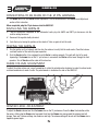
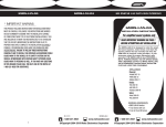
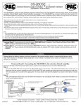
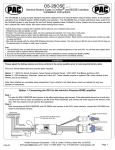
GM ONSTAR CLASS II DATA BUS INTERFACE
GMOS-01
Installation Instructions
The GMOS-01 is designed to be used in vehicles listed below to retain Onstar and
the warning chimes that are lost when the OEM radio is removed, and also provide a
12 volt accessory output for proper aftermarket radio operation. The GMOS-01 now
provides a Mute, Parking Brake, VSS or Speed Sense, and Reverse outputs to make
installing an aftermarket navigational radio simpler and less time consuming.
NOTE: This interface will also work in vehicles listed inside that are not
equipped with Onstar)
APPLICATIONS
See inside for application list.
* READ IMPORTANT WARNING
BEFORE ATTEMPTING ANY INSTALLATION
* IMPORTANT WARNING
THIS PRODUCT INCLUDES INSTRUCTIONS FOR INSTALLATION WHICH MUST BE CAREFULLY FOLLOWED. THE
INSTRUCTIONS ARE WORDED IN SUCH A MANNER TO ASSUME THAT THE INSTALLER IS CAPABLE OF COMPLETING THESE TYPE OF ELECTRONIC INSTALLATIONS. IF YOU ARE UNCLEAR AS TO WHAT YOU ARE
INSTRUCTED TO DO OR BELIEVE THAT YOU DO NOT UNDERSTAND THE INSTRUCTIONS SO AS TO PROPERLY
AND SAFELY COMPLETE THE INSTALLATION YOU SHOULD CONSULT A TECHNICIAN WHO DOES HAVE THIS
KNOWLEDGE AND UNDERSTANDING.
FAILURE TO FOLLOW THESE INSTRUCTIONS CAREFULLY AND TO INSTALL THE INTERFACE AS DESCRIBED
COULD CAUSE HARM TO THE VEHICLE OR TO SAFETY SYSTEMS ON THE VEHICLE. INTERFERENCE WITH
CERTAIN SAFETY SYSTEMS COULD CAUSE HARM TO PERSONS AS WELL.
IF YOU HAVE ANY QUESTIONS IN THIS REGARD PLEASE CALL THE HELP LINE OR THE METRA
AT: 1-800-221-0932 FOR ASSISTANCE.
1-800-221-0932
www.metraonline.com
© COPYRIGHT 2004-2010 METRA ELECTRONICS CORPORATION
Rev. 09-01-10
GMOS-01
GMOS-01 APPLICATIONS
BUICK
GMC
Century
LaCrosse/ Allure
2004-2005
2005-2009
Canyon
Envoy
2004-2010
2002-2009
Rainier
2004-2007
Savana
2003-2007
Rendevous
2002-2007
Sierra Classic
2007
Terraza
2005-2008
Sierra
2003-2006
Yukon / Yukon XL
2003-2006
CHEVROLET
HUMMER
Avalanche
2003-2006
H3
Cavalier
2000-2005
ISUZU
Colorado
2004-2010
Ascender
2003-2008
Express
2003-2007
I series pickup
2006-2008
Impala
2000-2005
OLDSMOBILE
Malibu
2001-2003
Alero
2001-2004
Malibu Classic
2004-2005
Bravada
2002-2004
Monte Carlo
2000-2005
Intrigue
2002
Silverado Classic
2007
Silhouette
2000-2004
Silverado
2003-2006
PONTIAC
SSR
2003-2006
Aztec
2001-2005
Suburban
2003-006
Grand Am
2001-2005
Tahoe
2003-2006
Grand Prix
2004-2008
Trailblazer
2002-2009
Montana SV6 (Canada) 2005-2008
Uplander
2005-2008
Montana
2000-2005
Venture
2000-2005
Sunfire
2000-2005
2006-2009
SAAB
9-7x
2005-2009
SATURN
Relay
1
2005-2007
GMOS-01
INTERFACE COMPONENT
• GMOS-01 Data Interface • 14 pin harness with stripped leads
• 12 pin harness to 12 and 24 pin GM harness with stripped leads
TOOLS REQUIRED FOR INSTALLATION
• Cutting Tool • Tape • Crimping Tool
• Connectors (ie: butt-connectors, bell caps, etc.)
WIRING UP THE GMOS-01
* Important: Before beginning any of the following, disconnect the negative battery terminal to prevent accidental short circuit.
**Note: The ignition power source of most factory GM radios keep the radio on until one of the doors is
opened. This is called the R.A.P. (retained accessory power). The GMOS-01 is designed to retain this feature.
FOR AFTERMARKET RADIO ONLY:
CONNECTIONS TO BE MADE ON THE 14 PIN HARNESS:
1. Connect the red wire to the ignition/accessory wire of the aftermarket radio.
2. Connect the orange/white wire to the illumination wire of the aftermarket radio. If the aftermarket
radio has no illumination wire just tape off the orange wire.
3. Connect the blue/white wire to the amp turn on wire of the aftermarket radio and to the blue/white wire
in the 24 pin harness.
4. Connect the white wire to the left front positive speaker output of the aftermarket radio.
5. Connect the white/black wire to the left front negative speaker output of the aftermarket radio.
6. Connect the gray wire to the right front positive speaker output of the aftermarket radio.
7. Connect the gray/black wire to the right front negative speaker output of the aftermarket radio.
8. Connect the brown wire to the mute wire of the aftermarket radio. If the after market radio does not have
a Mute wire, tape up the brown wire.
The following wires on the 14 pin harness are for the aftermarket radios that have navigation built in:
1. Connect the green wire to the parking brake wire of the aftermarket navigation radio.
2. Connect the blue/pink wire to the VSS or speed sense wire of the aftermarket navigation radio.
3. Connect the green/purple wire to the reverse wire of the aftermarket navigation radio.
When completed, plug the 14 pin harness into the GMOS-01.
2
GMOS-01
CONNECTIONS TO BE MADE ON THE 24 PIN GM HARNESS:
1. Connect the yellow wire to the radio’s 12 volt battery or memory wire.
2. Connect the black wire to the radio’s ground wire.
3. Connect the blue/white wire to the amp turn on wire of the aftermarket radio and to the blue/white wire of
the 14 pin harness.
4. Connect the green wire to the radio’s left rear positive speaker output.
5. Connect the the green/black wire to the radio’s left rear negative speaker output.
6. Connect the purple wire to the radio’s right rear positive speaker output.
7. Connect the purple/black wire to the radio’s right rear negative speaker out put.
8. The Orange and Orange/White wires are not used. Please tape up wires to avoid a short circuit output.
CONNECTIONS TO BE MADE ON THE 12 PIN HARNESS:
1. The brown wire is for the Onstar volume adjustment. This will be discussed in the Onstar Level Adjustment
section of this instruction.
When completed, plug the 12 pin harness into the GMOS-01.
FOR AFTERMARKET RADIO AND AMPLIFIER
(See wiring diagram on page 6)
CONNECTIONS TO BE MADE ON THE 14 PIN HARNESS:
1. Connect the red wire to the ignition/accessory wire of the aftermarket radio.
2. Connect the Orange/white wire to the illumination wire of the aftermarket radio. If the aftermarket radio
has no illumination wire just tape off the orange wire.
3. Connect the blue/white wire to the amp turn on wire of the aftermarket radio
and to the blue/white wire in the 24 pin harness.
4. White NOT USED
5. White/black NOT USED
6. Gray NOT USED
7. Gray/black NOT USED
8. Connect the Brown wire to the mute wire of the aftermarket radio. If the after market radio does not have a
Mute wire, tape up the Brown wire.
The following wires on the 14 pin harness are for the aftermarket radios that
have navigation built in:
1. Connect the Green wire to the parking brake wire of the aftermarket navigation radio.
3
GMOS-01
Continued:
The following wires on the 14 pin harness are for the aftermarket radios that
have navigation built in:
2. Connect the Blue/Pink wire to the VSS or speed sense wire of the aftermarket navigation radio.
3. Connect the Green/Purple wire to the reverse wire of the aftermarket navigation radio.
When completed, plug the 14 pin harness into the GMOS-01.
CONNECTIONS TO BE MADE ON THE 24 PIN GM HARNESS:
1. Connect the yellow wire to the radio’s 12 volt battery or memory wire.
2. Connect the black wire to the radio’s ground wire.
3. Connect the blue/white wire to the amp turn on wire of the aftermarket radio and to the blue/white wire of
the 14 pin harness.
4. Connect the green wire to the amplifier’s left rear positive speaker output.
5. Connect the the green/black wire to the amplifier’s left rear negative speaker output.
6. Connect the purple wire to the amplifier’s right rear positive speaker output.
7. Connect the purple/black wire to the amplifier’s right rear negative speaker output.
8. The Orange and Orange/White wires are not used. Please tape up wires to avoid a short circuit output.
9. Cut the white wire about half way between the two plugs. Connect the white wire from the 24 pin plug to
amplifier’s left front positive speaker output wire. Connect the white wire from the 12 pin plug to the positive
speaker wire of the Metra SP-2003 or equivalent.
10. Cut the white/black wire about half way between the two plugs. Connect the white/black wire from the 24
pin plug to amplifier’s left front negative speaker output wire. Connect the white/black wire from the 12 pin
plug to the negative speaker wire of the Metra SP-2003 or equivalent.
11. Cut the gray wire about half way between the two plugs. Connect the gray wire from the 24 pin plug to amplifier’s right front positive speaker output wire. Connect the gray wire from the 12 pin plug to the positive
speakerwire of the Metra SP-2003 or equivalent.
12. Cut the gray/black wire about half way between the two plugs. Connect the gray/black wire from the 24 pin
plug to amplifier’s right front negative speaker output wire. Connect the gray/black wire from the 12 pin plug
to the negative speaker wire of the Metra SP-2003 or equivalent.
Note: If only one SP-2003 is used tape up the gray wires that would normally connect to the second
SP-2003 to avoid a short circuit.
4
GMOS-01
CONNECTIONS TO BE MADE ON THE 12 PIN HARNESS:
1. The brown wire is for the Onstar volume adjustment. This will be discussed in the Onstar Level Adjustment
section of this instruction.
When completed, plug the 12 pin harness into the GMOS-01.
INSTALLING THE GMOS-01
1. With all connections completed to the aftermarket radio, plug the GM24 and GM12 pin harnesses into the
vehicles wiring harnesses.
2. Reconnect the negative battery terminal.
3. Cycle the key by turning the ignition on then back off, then on again to test the radio.
TESTING THE GMOS-01
1. Turn the ignition on if not already, and then turn the radio on to verify that the radio works. Check the balance
and fader control of the radio for proper operation.
2. Push the Onstar button (if so equipped) to verify Onstar is working properly. The radio will shut off or mute,
depending if the brown wire on the 14 pin harness is connected, and Onstar will be heard through the front
speakers. Turn off Onstar and the radio will turn back on.
CHIME VOLUME ADJUSTMENT
To adjust the chime volume,use a small screwdriver to rotate the potentiometer clockwise to make the chime louder
and counterclockwise to make it softer. The potentiometer is located on the side of the GMOS-01.
ONSTAR LEVEL ADJUSTMENT
To adjust the Onstar volume level find the brown wire on the 12 pin harness. Press the blue Onstar button, while
the voice is talking tap the Brown wire to ground. Each time the Brown wire sees ground the volume level will
change. There are 3 volume settings, low, medium, and high. The volume setting will be set until the Brown wire is
tapped to ground again.
5
6
RADIO
CHIME VOLUME
ADJUSTMENT
UE
BL
RF+
RF -
LF+
LF RF +
RF -
X
X
X
X
LR +
RR RR
E
HIT
/W R+
L
GM
12 PIN
TO ONSTAR
12 PIN GM AUDIO
CONNECTOR
TO AFTERMARKET
REAR AMPLIFIER
GM 24 PIN
TO AFTERMARKET
FRONT AMPLIFIER
SP-2003
SP-2003
BROWN
GMOS-01
BLK
YEL
OPTIONAL
REQUIRED
12 PIN
LF+
LF-
ORANGE/WHITE
RED
GREEN
BLUE/PINK
GREEN/PURPLE
BROWN
BLUE/WHITE
14 PIN
AFTERMARKET RADIO AND AMPLIFIER WIRING
GMOS-01
GMOS-01 INSTRUCTIONS
FINAL WIRING CONNECTIONS
STRIP
Make wiring connections using the EIA color code chart shown below and the
instructions included with the head unit. Metra recommends making connections as shown below; Strip, Splice, Solder, Tape. Isolate and individually tape
off ends of any unused wires to prevent electrical short circuit.
SPLICE
SOLDER
TAPE
1-800-221-0932
www.metraonline.com
REV. 09/01/10 © COPYRIGHT 2004-2010 METRA ELECTRONICS CORPORATION INSTGMOS-01