1
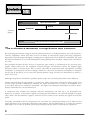
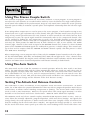
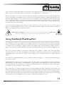
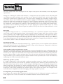
®
162SL
Compressor/Limiter
User Manual
IMPORTANT SAFETY INSTRUCTIONS
WARNING FOR YOUR PROTECTION
READ THE FOLLOWING:
CAUTION
RISK OF ELECTRIC SHOCK
DO NOT OPEN
A T T E N T I O N : RISQUE DE CHOC ELECTRIQUE - NE PAS OUVRIR
W A R N I N G : TO REDUCE THE RISK OF FIRE OR ELECTRIC
SHOCK DO NOT EXPOSE THIS EQUIPMENT TO RAIN OR MOISTURE
The symbols shown above are internationally accepted
symbols that warn of potential hazards with electrical
products. The lightning flash with arrowpoint in an equilateral triangle means that there are dangerous voltages
present within the unit. The exclamation point in an equilateral triangle indicates that it is necessary for the user to
refer to the owner’s manual.
These symbols warn that there are no user serviceable
parts inside the unit. Do not open the unit. Do not
attempt to service the unit yourself. Refer all servicing to
qualified personnel. Opening the chassis for any reason
will void the manufacturer’s warranty. Do not get the unit
wet. If liquid is spilled on the unit, shut it off immediately
and take it to a dealer for service. Disconnect the unit
during storms to prevent damage.
KEEP THESE INSTRUCTIONS
HEED ALL WARNINGS
FOLLOW ALL INSTRUCTIONS
DO NOT USE THIS APPARATUS NEAR WATER
CLEAN ONLY WITH A DRY CLOTH.
DO NOT BLOCK ANY OF THE VENTILATION OPENINGS. INSTALL IN ACCORDANCE WITH
THE MANUFACTURER’S INSTRUCTIONS.
DO NOT INSTALL NEAR ANY HEAT SOURCES SUCH AS RADIATORS, HEAT REGISTERS,
STOVES, OR OTHER APPARATUS (INCLUDING AMPLIFIERS) THAT PRODUCE HEAT.
ONLY USE ATTACHMENTS/ACCESSORIES SPECIFIED BY THE MANUFACTURER.
UNPLUG THIS APPARATUS DURING LIGHTNING STORMS OR WHEN UNUSED FOR LONG
PERIODS OF TIME.
Do not defeat the safety purpose of the polarized or grounding-type plug. A polarized plug has two blades with one wider than the other. A grounding type plug has
two blades and a third grounding prong. The wide blade or third prong are provided for your safety. If the provided plug does not fit your outlet, consult an electrician for replacement of the obsolete outlet.
Protect the power cord from being walked on or pinched particularly at plugs, convenience receptacles, and the point where they exit from the apparatus.
SAFETY INSTRUCTIONS
NOTICE FOR CUSTOMERS IF YOUR UNIT IS EQUIPPED
WITH A POWER CORD.
Use only with the cart stand, tripod bracket, or table specified by the manufacture,
or sold with the apparatus. When a cart is used, use caution when moving the
cart/apparatus combination to avoid injury from tip-over.
WARNING: THIS APPLIANCE MUST BE EARTHED.
The cores in the mains lead are coloured in accordance with
the following code:
GREEN andYELLOW - Earth
BLUE - Neutral
BROWN - Live
As colours of the cores in the mains lead of this appliance may
not correspond with the coloured markings identifying the terminals in your plug, proceed as follows:
• The core which is coloured green and yellow must
be connected to the terminal in the plug marked
with the letter E, or with the earth symbol, or
coloured green, or green and yellow.
• The core which is coloured blue must be connected to the terminal marked N or coloured black.
• The core which is coloured brown must be connected to the terminal marked L or coloured red.
This equipment may require the use of a different line cord,
attachment plug, or both, depending on the available power
source at installation. If the attachment plug needs to be
changed, refer servicing to qualified service personnel who
should refer to the table below. The green/yellow wire shall be
connected directly to the units chassis.
CONDUCTOR
WIRE COLOR
Normal
Alt
L
LIVE
BROWN
BLACK
N
NEUTRAL
BLUE
WHITE
E EARTH GND GREEN/YEL
GREEN
WARNING: If the ground is defeated, certain fault conditions in
the unit or in the system to which it is connected can result in
full line voltage between chassis and earth ground. Severe injury
or death can then result if the chassis and earth ground are
touched simultaneously.
Refer all servicing to to qualified service personnel. Servicing is required when
the apparatus has been damaged in any way, such as power-supply cord or plug is
damaged, liquid has been spilled or objects have fallen into the apparatus, the apparatus has been exposed to rain or moisture, does not operate normally, or has been
dropped.
POWER ON/OFF SWITCH: For products provided with a power switch, the power
switch DOES NOT break the connection from the mains.
MAINS DISCONNECT: The plug shall remain readily operable. For rack-mount or
installation where plug is not accessible, an all-pole mains switch with a contact
separation of at least 3 mm in each pole shall be incorporated into the electrical
installation of the rack or building.
FOR UNITS EQUIPPED WITH EXTERNALLY ACCESSIBLE FUSE RECEPTACLE: Replace fuse
with same type and rating only.
MULTIPLE-INPUT VOLTAGE: This equipment may require the use of a different line
cord, attachment plug, or both, depending on the available power source at installation. Connect this equipment only to the power source indicated on the equipment
rear panel. To reduce the risk of fire or electric shock, refer servicing to qualified
service personnel or equivalent.
This Equipment is intended for rack mount use only.
IMPORTANT SAFETY INSTRUCTIONS
U.K. MAINS PLUG WARNING
ELECTROMAGNETIC
COMPATIBILITY
This unit conforms to the Product
Specifications noted on the Declaration
of Conformity. Operation is subject to
the following two conditions:
• this device may not cause harmful
interference, and
• this device must accept any interference received, including interference
that may cause undesired operation.
Operation of this unit within significant
electromagnetic fields should be avoided.
• use only shielded interconnecting
cables.
A molded mains plug that has been cut off from the cord is unsafe.
Discard the mains plug at a suitable disposal facility. NEVER UNDER
ANY CIRCUMSTANCES SHOULD YOU INSERT A DAMAGED OR CUT
MAINS PLUG INTO A 13 AMP POWER SOCKET. Do not use the
mains plug without the fuse cover in place. Replacement fuse covers
can be obtained from your local retailer. Replacement fuses are 13
amps and MUST be ASTA approved to BS1362.
DECLARATION OF
CONFORMITY
Manufacturer’s Name:
dbx Professional Products
Manufacturer’s Address: 8760 S. Sandy Parkway
Sandy, Utah 84070, USA
declares that the product:
Product name: dbx 162SL
Note: Product name may be suffixed by the
letters-EU.
Product option:
None
conforms to the following Product Specifications:
Safety:
IEC 60065 (1998)
EMC:
EN 55013 (1990)
EN 55020 (1991)
Supplementary Information:
The product herewith complies with the requirements
of the Low Voltage Directive 72/23/EEC and the EMC
Directive 89/336/EEC as amended by Directive
93/68/EEC.
Vice-President of Engineering
8760 S. Sandy Parkway
Sandy, Utah 84070, USA
Date: January 30, 2004
European Contact:
Your local dbx Sales and Service
Office or
Harman Music Group
8760 South Sandy Parkway
Sandy, Utah 84070 USA
Ph: (801) 566-8800
Fax: (801) 568-7583
Introduction
. . . . . . . . . . . . . . . . . . . . . . . . . . . . . . . . . . . . . . . . . . . . . . . . . . . . . . . . . .3
Why you need compression . . . . . . . . . . . . . . . . . . . . . . . . . . . . . . . . . . . . . . . .3
The difference between compressors and limiters . . . . . . . . . . . . . . . . . . . . . .4
The compression and limiting effects . . . . . . . . . . . . . . . . . . . . . . . . . . . . . . . . .5
Limiters and PeakStopPlus™ . . . . . . . . . . . . . . . . . . . . . . . . . . . . . . . . . . . . . . . . . . . .6
Features . . . . . . . . . . . . . . . . . . . . . . . . . . . . . . . . . . . . . . . . . . . . . . . . . . . . . . . . .7
Connection To Your System
Operating Controls
. . . . . . . . . . . . . . . . . . . . . . . . . . . . . . . . . . . . . . . . .9
. . . . . . . . . . . . . . . . . . . . . . . . . . . . . . . . . . . . . . . . . . . . . . . . . .10
Front Panel Description . . . . . . . . . . . . . . . . . . . . . . . . . . . . . . . . . . . . . . . . . . . .10
Rear Panel Description . . . . . . . . . . . . . . . . . . . . . . . . . . . . . . . . . . . . . . . . . . . . .15
Operating Notes
. . . . . . . . . . . . . . . . . . . . . . . . . . . . . . . . . . . . . . . . . . . . . . . . . . . . .17
OverEasy® and hard knee . . . . . . . . . . . . . . . . . . . . . . . . . . . . . . . . . . . . . . . . . .17
Using the Compression Control . . . . . . . . . . . . . . . . . . . . . . . . . . . . . . . . . . . . . .17
Using the Stereo Couple Switch . . . . . . . . . . . . . . . . . . . . . . . . . . . . . . . . . . . . .18
Using the Auto Switch . . . . . . . . . . . . . . . . . . . . . . . . . . . . . . . . . . . . . . . . . . . . .18
Setting the Attack and Release Controls . . . . . . . . . . . . . . . . . . . . . . . . . . . . . . .18
Using PeakStop®/PeakStopPlus® . . . . . . . . . . . . . . . . . . . . . . . . . . . . . . . . . . . . .19
Specific Applications . . . . . . . . . . . . . . . . . . . . . . . . . . . . . . . . . . . . . . . . . . . . . . .20
Sidechain Applications . . . . . . . . . . . . . . . . . . . . . . . . . . . . . . . . . . . . . . . . . . . . .21
Technical Support/Factory Service
Warranty
. . . . . . . . . . . . . . . . . . . . . . . . . . . . . . . . . .25
. . . . . . . . . . . . . . . . . . . . . . . . . . . . . . . . . . . . . . . . . . . . . . . . . . . . . . . . . . . .25
Block Diagram
Specifications
. . . . . . . . . . . . . . . . . . . . . . . . . . . . . . . . . . . . . . . . . . . . . . . . . . . . . .26
. . . . . . . . . . . . . . . . . . . . . . . . . . . . . . . . . . . . . . . . . . . . . . . . . . . . . . . .27
Why You Need A Compressor
A remarkable feature of the human ear is that it can detect an extremely wide range of amplitude
changes - from the slightest whisper to a deafening clap of thunder. If one tries to record or reproduce
this wide spectrum of sound with the help of amplifiers, cassette recorders, records, or even digital
recorders, one is immediately restricted by the physical limitations of electronic and acoustic sound
reproduction technology.
The useable dynamic range of electronic audio equipment is limited as much at low levels as at high
levels. The thermal noise of electrons in the components results in an audible noise floor and thus represents the bottom limit of the transmission range.
The upper limit of useable dynamic range is determined by the levels of the internal operating voltages;
if they are exceeded, audible signal distortion is the result. Although in theory the useable dynamic range
sits between these two limits, it is considerably smaller in practice, since a certain reserve must be maintained to avoid distortion of the audio signal if sudden noise peaks occur. Technically speaking, we refer
to this reserve as headroom--usually about 10-20dB. A reduction of the operating level would allow for
greater headroom, i.e. the risk of signal distortion due to high level peaks would be reduced. However
at the same time, the basic signal to noise ratio of the program material would be increased significantly. It is therefore useful to keep the operating level as high as possible without risking signal distortion
in order to achieve optimum transmission quality. It is possible to further improve the transmission quality by constantly monitoring the program material with the aid of a volume fader, which manually
changes the level of the program material. During low passages the gain is increased, and during loud
passages the volume is decreased. Of course it is fairly obvious that this kind of manual control is rather
restrictive; it is difficult to detect signal peaks and almost impossible to level them out. Manual control
is simply not fast enough to be satisfactory.
The need therefore arises for a fast acting automatic gain control system which will constantly monitor
the signals and which will always adjust the gain to maximize the signal-to-noise ratio without incurring
signal distortion. This device is called a compressor or limiter.
3
Clipping
Clipped signal heavily distorted
Headroom
Operating Level
Dynamic
Range
Useable dynamic range
Noise Floor
Audio levels below here are not heard, because of noise
i
i
The Difference
Between Compressors
and Limiters
By measuring the dynamic range of musical instruments in live recording situations, you will experience
extreme amplitudes which will often lead to overload in subsequent signal processing equipment.
Especially in broadcasting and digital recording, these signal peaks can lead to heavy distortion. To avoid
this kind of distortion or, to avoid loudspeakers being damaged by overload, compressors and limiters
are used.
The principle function of these devices is automatic gain control, as mentioned in the previous paragraphs, which reduces the the amplitude of loud passages and therefore restricts the original signal
dynamics within a desired range. This is useful, especially in conjunction with microphone recording
techniques, to compensate for level changes which are caused by inconsistent microphone techniques
on the part of the player, or to restrict the natural dynamic range of voices or instruments to achieve a
more even level.
Although compressors and limiters perform similar tasks, one essential point makes them different:
Limiters abruptly limit the signal above a certain level, while compressors control the signal “gently” over
a wide range. A limiter continuously monitors the signal and intervenes as soon as an adjustable level
is exceeded. This level is called the “threshold”. Any signal exceeding this threshold level will be immediately held below the set threshold level.
A compressor also monitors the program material continuously and also has a set threshold level.
However, in contrast to the limiter, signals exceeding the threshold are not reduced abruptly, but gradually. Above the threshold the signal is reduced in level relative to the amount the signal exceeds this
point.
Generally, threshold levels for compressors are set below the normal operating level to allow for the
upper dynamics to be musically compressed. For limiters, the threshold point is set above the normal
operating level in order to provide peak signal limiting and thus protects subsequent equipment.
4
The Compression and Limiting Effects
On a compressor, there is a relationship between the input signal, and the threshold level, input, output, and ratio settings. Look at an input signal applied to the inputs of two compressors. The threshold
level of the second unit is set ten decibels higher than the threshold of the first unit. Since a compressor only affects signals that exceed the threshold level, it is obvious that the signal of the first compressor will be compressed more, because it exceeds the threshold level more than the level of the second
unit, because the second compressor’s threshold level is set higher.
input
dBu
input
dBu
+10
+10
0
0
-10
-10
-20
-20
input
dBu
+10
0
Input of compressors at
different threshold settings.
-10
= threshold
time
-20
time
Figure 1
Figure 2
time
Figure 1
The difference between compression and limiting is shown visually below. In the first diagram below,
compression “squashes” the signal. Its peaks are lowered, but the overall level of the signal is raised due
to applied make-up gain (Output Gain). In the second diagram, the peaks are lowered to the threshold
level, but the rest of the signal has not been altered.
output
dBu
output
dBu
+10
+10
0
0
-10
-10
Difference in output of
compressors and limiters.
= threshold
-20
-20
time
Figure 3
time
Figure 4
Obviously, there is a large difference between these two signals in relation to their dynamic range and
the processed signal. In the third figure, it is shown to have been compressed, and in the fourth figure,
it has been limited.
5
Furthermore, it is interesting to note that by comparing the input and output waveforms for the compressed mode, the quietest sections of the input signal have been effectively raised in level, whereas the loudest sections have been effectively decreased in level. The overall effect is that both ends
of the dynamic range have been pushed toward the middle. This squashing effect of compression is
important to remember and highlights the major difference between compressing and limiting.
Compressing and limiting differ in one more aspect: the dynamic settings for attack and release times.
Attack time is defined as the time taken to for a compressor to respond to program levels which have
exceeded the threshold point. Release time is the amount of time a compressor takes to return the
program level to its original level, after the last excursion over the threshold point. For compression,
a preferably longer attack and release time are generally the best in order to keep the overall output
signal within a specified dynamic range. For limiting applications, considerably shorter attack and
release times are necessary to control fast transient signals or to increase headroom.
To achieve inaudible compression, it is advisable to work with program dependent attack and release
times. The advantage of program dependent compression is most apparent when processing musical material that is varied.
The dbx 162SL Stereo Compressor is suitable for all applications because of the ability to manually
set both attack and release parameters.
Limiters and PeakStopPlus®
Lower frequencies work best when compressed with slower attack times. When compressing a mix
that includes a wide range of frequencies, a compromise is made when setting the attack time. The
attack setting would generally suit the lowest frequency components of the material. For general
dynamic range control with a compressor, this is of no serious consequence.
However, in a “limiting” situation, where we are restricting the peaks of our signal to a maximum
operating level to avoid distortion in subsequent devices, a slow attack time is not acceptable. This
would result in very fast high frequency signal transients passing through unaffected by gain reduction. These transients could then cause distortion in the following equipment such as tape recorders
and radio transmitters. It is therefore necessary to choose an attack time which is as close to “zero”
attack as possible, independent of the frequency.
This makes the limiter necessary, and it’s why we include a peak limiter on almost all of our compression products. The dynamics of the dbx limiters are set to handle these fast transients through a
process called PeakStop and the newer, improved two-stage process called PeakStopPlus.
The first stage of PeakStopPlus is the Instantaneous Transient Clamp™ which clamps the signal with
a soft logarithmic clamp function. This logarithmic function assures that the signal will not exceed
the level set by the PeakStopPlus LEVEL control by more than 2 dB typically, and that it will not
introduce harsh artifacts. The second stage is a unique program limiter featuring Intelligent Predictive
Limiting™. Its function is to monitor the input signal and intelligently predict the amount of gain
reduction needed to keep the output signal below the ceiling set by the Instantaneous Transient
Clamp™. Note, since the PeakStopPlus limiter is a fail-safe limiter it must come after the OUTPUT
6
GAIN control. If the output gain is set too high as compared to the PeakStopPlus Level control, continuous limiting can occur. While PeakStopPlus is typically used as a protective function, creative
effects can be achieved by intentionally driving the signal into heavy PeakStopPlus limiting. Great
care has gone into the design of the PeakStopPlus limiter to keep it acoustically transparent.
Appropriate use of it can protect your gear while keeping the signal free of artifacts.
For best results the Limiter functions of your compressor should be used in conjunction with the
Compressor functions.
Features
When we at dbx decided to make a premium compressor that would perform to the industry’s highest standards, it became readily obvious that every component and design strategy had to be chosen
with high-performance foremost in mind. After the revolutionary process of engineering design and
implementation was complete, the result was stunning. Here is a partial list of the features found on
the 162SL. You won’t hear about most of them anywhere else, but they are
critical to the amazing specs, comprehensive functionality, and visionary
design of the 162SL Stereo Compressor.
• Precision 1% metal film resistors.
• Gold-palladium-nickel board-to-board connectors.
• Jensen® Output transformers.
• Gold-plated Neutrik® XLR connectors.
• Rare earth magnet relays with gold contacts in a hermetically
sealed nitrogen environment.
• Military-grade glass epoxy circuit boards.
• Toroid transformer.
• Custom-machined, 1/4” thick front panel.
• Hand-crafted, solid aluminum knobs.
• LEDs mounted in machined, stainless steel housings.
• Custom dbx VU meters with peak indicators.
• Switchable OverEasy®/hard knee characteristics enable the 162SL to
sound like the traditional 165A as well as the old and still popular 160.
• Program dependent Auto mode, or fully variable attack and
release.
• PeakStop/PeakStopPlus® switchable limiting topologies, the perfect
complement to the 162SL feature set.
• Sidechain capabilities, switchable from the front panel.
7
Connections
The 162SL is connected for operation using the rear panel XLR or 1/4” connectors. Note that the two
rear panel input sections have a push-switch which lifts the contact on pin #1 (ground). Keep this switch
in the OFF position (pin #1 connected) until all connections are made. Be sure that your input and output cables are wired in the “pin 2/tip” configuration, which is printed on the rear panel of the 162SL.
For more information on other types of connections, refer to the section entitled Operating Notes.
When connecting the 162SL, refer to the following steps:
• Turn OFF all equipment BEFORE making any connections.
• Mounting the 162SL
The 162SL requires a two rack-space height (3.5 inches) and a standard
19 inch rack-space width. It can be mounted above or below (leaving
1U of space above and below the unit) anything that doesn’t create
excessive heat. This is to ensure proper ventilation. Ambient temperatures should not exceed 113°F (45°C) when equipment is powered.
Caution: Never remove the cover. There are no user serviceable parts inside.
• Make connections via XLR or 1/4” connectors.
• Plug in AC power cable and power ON the unit.
Note: Check the line voltage printed on the rear panel of the 162SL and verify that
it is correct for your area.
POWER
PHONE:
TIP
RING
SLEEVE
28 WATTS
CHANNEL 2
OUTPUTS
SIDECHAIN
FUSE REPLACEMENT RATINGS
100V-120V
T 400mA L 250V
220V-240V
T 200mA L 250V
RETURN
XLR:
PIN 1
PIN 2
PIN 3
INTPUTS
SIDECHAIN
RETURN
-10 dBV
LIFT
A: Channel One shows processing of a
OUTPUT
INPUT
B
INTPUTS
GND
+4 dBu
SEND
-10 dBV
LIFT
CHANNEL ONE
CHANNEL TWO
Two Basic Compressor Setups:
CHANNEL 1
OUTPUTS
GND
+4 dBu
SEND
OUTPUT
INPUT
A
group or aux master output. Signal goes
to the 162SL input from the
output/insert send of the console, and
returns to the console via the
input/insert return of the same
group/aux on the console.
B: Channel Two shows connections for
processing a signal from a single channel. Input of the 162SL is fed by the
channel insert output/send, and returns
to the console via the insert
input/return.
9
Front Panel Controls
OverEasy® Switch: This switch activates/deactivates the OverEasy® characteristics of the 162SL. When
the switch is IN, the 162SL is in OVEREASY mode. OverEasy is a process which allows the user to
compress a signal more gently than a hard knee compressor through the threshold region. This
action produces a much smoother “natural-sounding” compression effect. When the OverEasy
switch is OUT, the regular, hard knee action of the compressor is active. Hard knee operation can
produce a much harder (hence the nick-name “hard knee”) compression effect as the signal passes
over the threshold level. Note that when the OverEasy switch is IN, the yellow LED above the
Threshold control lights whenever the input signal level is in the OverEasy region of compression.
In HARD KNEE mode the signal is either below the threshold and not being compressed, or it is above
the threshold and is being compressed, and therefore the yellow LED does not light. See the section entitled Operating Notes later in this manual for a more in-depth discussion of the differences
between OverEasy and hard knee compression.
Thr eshold Control: This control adjusts the signal amplitude (volume, or level) above which compression occurs. In OVEREASY mode the threshold of compression is defined as the approximate middle of the OverEasy region. The markings around the Threshold control are measured in dBu
(where 0dBu = .775V) and range from -40dBu (7.8mV rms) on the low end, to +20dBu (7.75V rms)
at the high end of the scale.
Thr eshold LEDs: These LEDs (above the Threshold control) indicate the relationship between the
input signal and the threshold set by the Threshold control. The green LED lights when the input
signal is below the set threshold. The yellow LED lights when the 162SL is set in OVEREASY mode via
the OverEasy switch, and the input signal level is in the OverEasy threshold range. The red LED
lights when the input signal level is above the set threshold. (See the section entitled Operating
Notes for a discussion on the differences between OverEasy and hard knee compression.)
Compression Control: This control adjusts the amount of compression that is applied to the input signal level when it exceeds the set threshold level. The amount of compression is expressed in a ratio
formula, where the first number of the ratio indicates the amount of input signal level in dB, and
the second number indicates the amount of output signal level, in dB, when the threshold is exceeded. For example, in HARD KNEE mode, the compression ratio of 5:1 means that for every 5dB of signal level that exceeds the set threshold level, the resultant output signal level is 1dB. Therefore if
the threshold level is exceeded by 15dB, and the compression ratio is set to a 5:1 ratio, the output
signal level will be 3dB. In OVEREASY mode, the ratio set by the Compression control is not reached
until the signal has passed through the OverEasy region of compression (the yellow LED turns off
and the red LED lights). When the ratio of ∞:1 is selected, the input signal level is “limited” to a 0dB
10
increase in output level, regardless of how far the set threshold level is exceeded. This occurs in
both OverEasy® and hard knee operation. Note that when a compressor is set to a compression
ratio of 10:1 or more, it may be considered to be LIMITING the input signal, especially when a fast
attack time is selected.
Auto Switch: This switch sets the 162SL for automatic or manual operation. When the Auto switch is
IN (AUTO mode), the compressor automatically adjusts its attack rate and release time to suit the program envelope. (This AUTO mode sets the compressor for the same attack and release characteristics
as dbx Models 160, 161, 162, 163 and 164 compressor/limiters.) When the Auto switch is OUT (MANUAL mode), the front panel Attack and Release rate controls determine the maximum rate of gain
change and the behavior of the level detector circuitry.
In AUTO mode, the 162SL utilizes the patented dbx RMS level detector with its program-dependent
attack/release characteristics to obtain natural-sounding compression or limiting. For special effects
and certain signal situations, however, it is often desirable to set fixed attack and release characteristics. MANUAL mode affords this capability. The AUTO mode is recommended for vocals as well as
instruments. Because the AUTO mode has a program dependent variable attack rate, the compressor
may compress or limit some program material smoother than in the MANUAL mode which has a fixed
attack characteristic. This is especially true on vocals.
Att ack and Release Controls: Attack time is defined as the time taken for a compressor to respond
to program levels which have exceeded the threshold point. For the 162SL, this control ranges from
400dB/mS (extremely fast) to 1dB/mS. Release time is the amount of time a compressor takes to
return the program level to its original level, after the last excursion over the threshold point. The
162SL’s release times range from 4000dB/second (very fast release time), to 10dB/second (slow
release time). A very fast attack setting (control maximum counterclockwise) will cause the compressor to act like a peak limiter even though RMS detection circuitry is used. Slower attack settings
cause the compressor to act like an RMS or averaging detecting compressor/limiter. To achieve
inaudible compression, it is advisable to work with program dependent attack and release times
(Auto mode). The advantage of program dependent compression is most apparent when processing
musical material that is varied. For compression, longer attack and release times are generally the
best in order to keep the overall output signal within a specified dynamic range. For limiting applications, considerably shorter attack and release times are necessary to control fast transient signals
or to increase headroom.
Stop Level Control: This control adjusts the maximum peak output level of the 162SL regardless of any
other control. The PeakStop limiter comes after the compression and all other circuitry, except the
output gain; this provides for an absolute peak limit to be put on the peak excursions at the output
via the Instantaneous Transient Clamp™. Since the PeakStopPlus® limiter is a fail-safe limiter it must
come after the Output Gain control. If the output gain is set too high as compared to the
PeakStopPlus® Level control, continuous limiting can occur. While PeakStopPlus is typically used
as a protective function, creative effects can be achieved by intentionally driving the signal into heavy
PeakStopPlus limiting. Like the range of the Threshold control, the scale of the Stop Level control
is measured in dBu. The control ranges from +4dBu, all the way to “OFF” (+24dBu). The top end of
the scale is marked “OFF” because its internal setting, +24dBu, is the actual maximum output level
of the 162SL, and therefore signal passing through the unit will pass untouched, up to the maximum
output level of the 162SL. Because of this, the limiter is effectively rendered “inactive” in the OFF setting.
11
PeakStopPlus® Switch and LED: The dynamics of the dbx 162SL are set to handle fast transients
through PeakStop® limiting and the newer PeakStopPlus. PeakStop is the process first introduced on
the dbx 165A compressor/limiter. PeakStop is made up of an extremely fast-reacting detector, called
Instantaneous Transient Clamp. The sound of PeakStop became popular as the 165A permeated the
audio industry, and quickly became the standard looked for by many top artists of the day. The latest implementation of this limiter topology is PeakStopPlus, first introduced in 1996 on the dbx 1066.
PeakStopPlus is made up of two different parts or stages. The first stage is the Instantaneous
Transient Clamp™ which clamps the signal with a soft logarithmic clamp function. This logarithmic
function assures that the signal will not exceed the level set by the PeakStopPlus Level control by
more than 2 dB typically, and that it will not introduce harsh artifacts. The second stage is a unique
program limiter featuring Intelligent Predictive Limiting™. Its function is to monitor the input signal
and intelligently predict the amount of gain reduction needed to keep the output signal below the
ceiling set by the Instantaneous Transient Clamp™.
Note that since the PeakStopPlus limiter is a fail-safe limiter it must come after the Output Gain control. If the output gain is set too high as compared to the PeakStopPlus LEVEL control, continuous
limiting can occur. While PeakStopPlus is typically used as a protective function, creative effects can
be achieved by intentionally driving the signal into heavy PeakStopPlus limiting. Great care has gone
into the design of the PeakStopPlus limiter to keep it acoustically transparent. Appropriate use of it
can protect your gear while keeping the signal free of artifacts.
A bi-color LED associated with both the Stop Level control and the PeakStopPlus switch indicates
when PeakStopPlus is activated. By pushing the PeakStopPlus switch to the IN position, the LED
lights in a green color when the signal level at the limiter circuit is BELOW the stop level set by the
Stop Level control. When the signal level attempts to exceed the level set by the Stop Level control, the LED lights in a red color.
When the limiter is in PEAKSTOP mode, the LED does not light in a green color, and only lights in a
red color when the signal attempts to exceed the set stop level, showing that the signal is being
reduced in level by the limiter.
Sidechain Switch and LED: This switch/LED provides access/visual feedback to the sidechain control. When the switch is IN, the LED is lit, and the 162SL is operating in sidechain mode. This means
that the compressor is set react to the audio signal presented at the Sidechain Return connector,
rather than to the audio signal presented at the regular audio input of the 162SL. The circuitry of the
162SL was designed in such a way as to make the audio path of the sidechain section very short and
clean. The selection of the sidechain function is made via “relay” switching, not allowing the signal
to pass through any unnecessary switches. The sidechain functions are convenient in many applications, such as broadcast engineering, where engineers are asked to provide “ducking” functions, as
well as de-essing. Frequency-specific and sustain-related compression are also possible with the use
of the sidechain functions of the 162SL. See the section entitled Operating Notes.
12
Bypass Switch and LED: This switch activates a hard-wire relay bypass system, which allows the
audio signal to pass through the compressor directly from input to output, even when the 162SL is
turned off. That is to say that the XLR Pin 2 at the input connector is directly connected to the XLR
Pin 2 at the output connector, and the XLR Pin 3 at the input connector is directly connected to the
XLR Pin 3 at the output connector. When the 162SL is in bypass mode the LED directly above the
Bypass switch is lit.
Note: Bypass mode can be very useful for applications such as A-B comparisons, comparing processed signal
with un-processed signal.
Output Gain Control: This control adjusts the amount of gain in the 162SL’s output amplifier stage.
The signal can be attenuated or boosted by a full 20dB relative to a “0” center setting, representing
unity gain. This control is independent of the threshold or compression ratio settings. Because 20dB
of gain can be added at the 162SL output, it is possible to cause clipping even when the input level
is within the specified range. When the compression ratio is set at a low number, extreme clockwise
rotation of the Output Gain control could cause the 162SL output stage to clip audio program peaks.
Therefore, for normal operation we suggest setting the Output Gain control to “0dB” (12 o’clock position) as a starting position. Where the circuit fed by the 162SL has a high input sensitivity, lowering
the output gain setting can avoid the need for an attenuation pad in subsequent equipment.
Pe ak LED: This LED is located to the left of the VU Meter. It is set to light when the signal level at the
output level reaches +21dBu. This represents a headroom measurement of approximately 3dB before
hard clipping will occur, due to the maximum output level of the 162SL (+24dBu).
VU Meter: The custom designed analog meter is made to serve 3 different functions: first, it measures
the amount of input signal presented at the input connector corresponding to its channel. Second, it
measures the output signal at the output connector, after all processing has taken place, including
output gain. Third, it shows the amount of gain reduction being induced into the input signal, measured after both the compressor settings and limiter settings. Note that the meter, in input and output mode, measures accurately from -30dB to +6dB. There is 15dB between the upper end of the
meter, and the setting at which the Peak LED lights. Be aware that while the occasional “pegging” of
the meter will likely not effect the internal dynamics of the 162SL, it is possible that the output signal from the 162SL could cause distortion in subsequent gear, if the output signal stays above the
+6dB marking on the meter for an extended period of time. The dynamic range of the 162SL is meant
to provide an extremely low noise floor at optimum operating level (“0”dB, which is +4dBu), and to
provide protection for the occasional excursion above the nominal operating range. It was not meant
to provide continuous operation in the 15dB of “no-man’s-land” between the upper end of the analog meter and the setting of the Peak LED.
In Gain Reduction mode, the meter moves to indicate the amount of gain reduction, in dB, the compressor/limiter settings are imposing on the output signal. When first activated, the meter’s needle
will jump to the “0” mark of the lower scale on the meter (only if there is no gain reduction happening), indicating “zero gain reduction”, and will move to the left indicating the amount of gain
reduction in the signal level, up to a maximum of 30dB of gain reduction.
13
Note that the gain reduction scale is linear in dB as opposed to the standard VU markings on the
upper scale on which input and output levels are monitored. This allows for easy visual indication
of gain reduction, as it can be read in a fraction of a second, with only a fleeting glance from the
engineer.
I n pu t Meter Selection Switch and LED: Selecting this mode via the switch allows the user to
monitor the incoming signal on the logarithmic (upper) scale of the VU meter. When in input mode,
the LED above the switch will light in a green color, indicating that input mode is selected. This works
in conjunction with the input level switch (+4dBu/-10dBV) on the back of the 162SL. When the rear
switch is set to +4dBu, a meter reading of 0VU corresponds to +4dBu input. When the rear switch
is set to -10dBV, a meter reading of 0VU corresponds to -10dBV input.
Output Meter Selection Switch and LED: Selecting this mode via the switch allows the user to monitor the outgoing signal on the logarithmic (upper) scale of the VU meter. When in output mode, the
LED above the switch will light in a yellow color, indicating that output mode is selected. This works
in conjunction with the input level switch (+4dBu/-10dBV) on the back of the 162SL. When the rear
switch is set to +4dBu, a meter reading of 0VU corresponds to +4dBu output. When the rear switch
is set to -10dBV, a meter reading of 0VU corresponds to -10dBV output.
Gain Reduction Meter Selection Switch and LED: Selecting this mode via the switch allows the
user to monitor the amount of gain reduction in dB, applied to the signal on the linear (lower) scale
of the VU meter. When in gain reduction mode, the LED above the switch will light in a red color,
indicating that gain reduction mode is selected. In gain reduction mode the meter displays the
amount of gain reduction resulting from the settings of both the compressor and PeakStopPlus® limiter.
Stereo Couple Switch and LED: This switch activates the stereo linkage between channels one and
two. When the switch is in the IN position, the two channels of the 162SL are linked together, and
the oversized yellow LED directly above the switch lights to indicate the selection. In stereo mode
channel one (the left side of the 162SL) is the “master” and channel two (the right side of the 162SL)
is the “slave”. When the two channels are linked together, the controls on the master side control the
settings of both channels of the 162SL. The controls on the slave side are disabled, although the meter
moves synchronous to the meter on the master side. In stereo mode, the 162SL uses a process called
True RMS Power Summing™. True RMS Power Summing combines the RMS signal energy (power)
of the audio signal of both channels and allows the 162SL to operate based on the signal information from both the right an left channels of audio signal.
Po wer LED: The Power LED is located directly above the Stereo Couple switch, at the center point of
the 162SL. It remains lit while the 162SL is connected to an appropriate power supply, and the Power
switch is in the ON position.
14
PHONE:
TIP
RING
SLEEVE
POWER
XLR:
PIN 1
PIN 2
PIN 3
28 WATTS
CHANNEL 2
OUTPUTS
FUSE REPLACEMENT RATINGS
100V-120V
T 400mA L 250V
220V-240V
T 200mA L 250V
SIDECHAIN
RETURN
INTPUTS
CHANNEL 1
OUTPUTS
GND
+4 dBu
SIDECHAIN
RETURN
SEND
-10 dBV
LIFT
INTPUTS
GND
+4 dBu
SEND
-10 dBV
LIFT
Rear Panel
Au dio Input and Output Connectors: Each audio input and output channel of the 162SL offers both
1/4” and XLR connectors. The connectors are default wired in balanced mode (pin 2 /tip hot),
although supplying an unbalanced signal presents no difficulty to the 162SL.
Pin 1 Lift Switch: Associated with each input connector is a switch labeled Pin 1 Lift. Depressing this
switch lifts pin 1 of the input XLR and the sleeve of the 1/4” connector from all ground references.
This may be necessary to break a troublesome ground loop which is causing hum in the system.
Sidechain Send and Return Connectors: When the front panel Sidechain switch is in the IN position, the 162SL RMS level detection is “listening” to the audio signal presented at the Sidechain Return
connector. Each channel features separate sidechain capabilities using the 1/4” TRS connectors as for
the main audio input and output connections. Each channel’s sidechain connections are marked
“send” for the output, and “return” for the input. When selected, the sidechain Send connector
“sends” the audio signal from the 162SL to the outboard gear in the sidechain loop. (ie: dbx 20 or
30 Series Graphic Equalizer or digital delay. See the section marked Operating Notes for more information on the sidechain functions of the 162SL.) The audio is processed, and sent from the output
of that device back to the 162SL via the Return connector. As the signal is brought back into the
162SL, its RMS level is used to trigger the compression/limiting. This allows the 162SL to be very versatile in many applications, from ducking to frequency-specific compression or limiting. Two separate cables are used in favor of the conventional single “Y” cable, because they supply balanced signal to the sidechain gear, and are much more convenient to locate and use in a fast-paced studio or
live sound environment.
AC Power Switch: Located above the AC Power connector, the AC Power switch turns the 162SL ON
and OFF. When the switch reveals the red portion of the switch, the AC power to the 162SL is ON.
When the switch is in the opposite position, no AC power is being supplied to the 162SL, regardless
of other power connections.
AC Power Connector: The AC Power connector is a standard IEC 320 power inlet receptacle, for use
with any IEC-type power cord (included with the 162SL). Connect this cable to any 50Hz or 60Hz AC
power source of the correct line voltage for your area. Make sure this voltage is also correct for the
voltage marked on the back of the 162SL. Always make AC power connections with the AC power
switch in the OFF position (see above). The 162SL consumes a maximum power of 28 watts.
Warning: Be sure to verify both your actual line voltage and the voltage for which your
162SL is wired, as indicated on the back panel of the unit. Connection to an
inappropriate power source may result in extensive damage which is not covered by the warranty.
15
OverEasy® And Hard Knee
In a typical hard-knee compressor, the threshold control sets a reference level above which input signals will be attenuated in the manner defined by the setting of the Compression ratio control. Input signals which fall below this level will pass through unprocessed. With OverEasy compression, signals
begin to gradually activate the 162SL's gain change circuitry as they approach the threshold reference
level and they do not get fully processed in the manner defined by the Compression control until they
have passed somewhat above the threshold reference level. There is no distinct point at which processing begins, and the threshold setting corresponds to a point on the input/output transfer curve midway between the onset of processing and that point at which the transfer curve corresponds to the setting of the Compression control. The following diagrams also show how the 162SL's threshold indicator
LEDs correlate with the compression curves.
1:1
1:1 Unity
+20
4:1
+5
20:1
0
:1
-5
Rotation Point Threshold
+15
4:1
+5
:1
0
-5
-10
A
E
MB
R
RED
Above Threshold
Range
VEREasy
EASY
® RANGE
OOver
G
-10
2:1
+10
EN
+10
RE
2:1
+15
OUTPUT LEVEL (dB)
OUTPUT LEVEL (dB)
+20
-15
-15
-15 -10
-5
0
Below Threshold
-15 -10
+5 +10 +15 +20
-5
0
+5 +10 +15 +20
INPUT LEVEL (dB)
INPUT LEVEL (dB)
OverEasy® compression
threshold and LEDs.
Hard knee compression
threshold point.
Using The Compression Control
When an input signal is above the threshold reference level, the setting of this control determines the
number of decibels by which the input signal must change in level to produce a 1dB increase in the signal level at the output of the 162SL. A setting of 2:1 indicates an input:output ratio wherein a 2dB
increase in input signal (above threshold) will produce a 1dB increase in output signal. A setting of ∞:1
indicates that an infinite increase in input level would be required to raise the output level by 1dB. In
other words, the output level is constant when the input signal is above threshold. The 162SL's
Compression control covers the entire range from 1:1 to ∞:1. The control curve of the compression
potentiometer has been designed to provide total operator control, with scale expansion at the subtle
lower ratios for easy, repeatable settings.
3
6
1:1
10
2
+20
20
Behavior of the 162SL’s
Compression control
OUTPUT LEVEL (dB)
1.5
+15
1
2:1
COMPRESSION
+10
4:1
+5
:1
0
-5
Threshold
-10
-15
-1:1
-15 -10
-5
0
+5 +10 +15 +20
INPUT LEVEL (dB)
17
Using The Stereo Couple Switch
Two channels of program material do not necessarily constitute a stereo program. A stereo program is
one where the two channels are recorded and/or mixed to create the illusion of a single unified panorama of sound. The stability of the psychoacoustic image of each sound source within the stereo spectrum
depends upon its ability to maintain a specific phase and amplitude relationship from the left to the right
channel.
If two independent compressors are used to process the stereo program, a loud sound occurring in one
channel will cause a gain reduction only in that channel. This gain reduction would cause the perceived
image of any sound spread between the two channels to move toward the side which had not been
compressed, because the spread signal would be momentarily softer in the compressed channel. This
can be avoided by linking the two compressors in such a way that both channels receive the same
amount of compression. On the 162SL, this is accomplished by means of the Stereo Couple switch. When
activated, the 162SL permits the RMS detectors of both channels to “talk” to one another. The SLAVE
channel (right, channel 2) then sends its signal to the MASTER channel (left, channel 1), where the RMS
power of the MASTER and SLAVE signals are combined to generate a control voltage. This control voltage is then used to compress both the MASTER and SLAVE channels equally. This dbx process is called
True RMS Power Summing™
When compressing a stereo program with a 162SL, only the MASTER channel controls need to be adjusted. The Threshold LEDs, Auto LED, and PeakStop (Plus) LED will not light on the “slave” channel when
the 162SL is stereo linked. The Bypass switch and LED, Sidechain switch and LED, and the Meter Mode
switches and LEDs remain channel-independent and function normally in linked mode.
Using The Auto Switch
The Auto switch sets the 162SL for automatic or manual operation. When the Auto switch is IN (Auto
mode), the LED indicator lights and the 162SL automatically adjusts its attack rate and release time to
suit the program envelope. (This Auto mode sets the 162SL for the same attack and release characteristics as dbx Models 160, 161, 162, 163, and 164 compressor/limiters), when the auto switch is out. The
LED indicator above it turns OFF, and the front panel Attack and Release rate controls determine the
maximum rate of gain change and the behavior of the level detector circuitry.
Setting The Attack And Release Controls
The 162SL offers a choice of automatic or user-adjustable attack and release characteristics. In AUTO
mode, the 162SL utilizes the patented dbx RMS level detector with its program-dependent attack/release
characteristics to obtain natural sounding compression or limiting. The AUTO mode works well for
vocals as well as most instruments. However, for special effects and certain signal situations, it is often
desirable to set fixed attack and release characteristics. MANUAL mode affords this capability.
The MANUAL attack and release controls employ AutoVelocityTM Dynamics (AVD) circuitry. AVD circuitry allows for manually adjustable, program-dependent, attack and release timings. For signals that
change slowly, they will experience a shorter attack and release time (roughly a factor of 10 times less
than the markings on the attack and release controls). For signals that change quickly (i.e. snare drum
hit) the attack and release times speed up to reflect the actual markings of the attack and release con-
18
trols. This faster attack time allows the transients to by captured and compressed without overshoot and
allows a quick release from compression without “punching holes” in the sound.
There is no right way to set the Attack and Release controls. Generally, you want a slow enough attack
to avoid pumping or breathing sounds caused when background sounds are audibly modulated by the
dominant signal energy, yet the release must be fast enough to avoid suppression of the desired signal
after a sudden transient or a loud note has decayed. Depending on the desired effect, you might want
a very slow attack so that percussive or transient sounds are not restricted, but average volume levels
are held within the desired range.
A very fast attack setting (control maximum counterclockwise) will cause the 162SL to act like a peak
limiter even though RMS detection circuitry is used. Slower attack settings cause the 162SL to act like an
RMS or averaging detecting compressor/limiter.
Note: Attack and Release controls operate together and in conjunction with the Compression
ratio control. Changing one control may necessitate changing another setting.
Using PeakStop®/PeakStopPlus®
The Stop Level control sets the maximum peak output level of the 162SL irrespective of any other control. PeakStop consists of a sophisticated voltage-controlled Instantaneous Transient Clamp™ that produces a minimum of audible distortion. It rounds the corners of a peak rather than cutting it off sharply,
as “clippers” do. By making a signal's leading and trailing edges curved instead of sharp corners, it
reduces the amount of higher odd-order, offensive-sounding harmonics that conventional clipping causes.
The level at which PeakStop is activated is adjustable from +4dBu to +24dBu. Note that small signal
excursions above the set value of PeakStop are possible, to allow the rounding to occur. Therefore, for
applications where you must not exceed a given ceiling, set the PeakStop control 1 to 2dB below the
ceiling.
To disable the PeakStop function, set the control to OFF (>+24dBu) (i.e: above the maximum output
level of the 162SL).
PeakStopPlus® is made up of two separate parts. The first stage is the Instantaneous Transient Clamp™
which clamps the signal with a soft logarithmic clamp function. This logarithmic function assures that
the signal will not exceed the level set by the PeakStopPlus® Level control by more than 2 dB typically, and that it will not introduce harsh artifacts.
The second stage is a unique program limiter featuring Intelligent Predictive Limiting™. Its function is to
monitor the input signal and intelligently predict the amount of gain reduction needed to keep the output signal below the ceiling set by the Instantaneous Transient Clamp™. Note, since the PeakStopPlus®
limiter is a fail-safe limiter it must come after the Output gain control. If the output gain is set too high
as compared to the PeakStopPlus® Level control, continuous limiting can occur.
19
While PeakStopPlus™ is typically used as a protective function, creative effects can be achieved by intentionally driving the signal into heavy PeakStopPlus™ limiting. Great care has gone into the design of the
PeakStopPlus™ limiter to keep it acoustically transparent. Appropriate use of it can protect your gear
while keeping the signal free of artifacts.
Specific Applications
Smoothing out variations in microphone levels
When the distance between a vocalist and a mic changes, variations in signal level occur. To smooth out
these variations, start with the 162SL adjusted for a low compression ratio (e.g., 4:1) and adjust the
Threshold control for optimum results, then increase the compression ratio if necessary. Due to the gentle OverEasy characteristic available on the 162SL allows even fairly high ratios to be handled transparently.
Smoothing out variations in musical instrument levels
To achieve a smoother electric bass sound, compress the instrument's output with a ratio of about 4:1.
Compression lessens the loudness variations among the strings and increases the sustain. Other instruments, such as horns, vary in loudness depending on the note being played, and benefit similarly.
Note: When compressing a stereo program with the 162SL, the factors affecting a compression
curve and the actual compression ratio and threshold settings are like those previously covered with reference to single channels of program material. However, it will generally be
found that large amounts of compression are more audible in a mixed stereo program than
they might be on the separate tracks that were mixed to create the program.
Raising a signal out of a mix
Since reducing dynamic range increases the average signal level by a small amount, a single track can
be raised out of a mix by boosting its level slightly and applying compression. It is also possible to separate certain vocals or instruments from a mono program already mixed by frequency-weighted compression.
Using your EQ to reduce feedback in live settings
You can use your 162SL and an EQ (a dbx 20 or 30 Series graphic EQ) to reduce feedback in clubs or
halls by placing the 162SL at ∞:1, hard knee, and a low threshold. Increase the output gain until the first
feedback ring occurs. The 162SL will catch it, and hold it as a constant tone so you can adjust your EQ
to minimize it. Continue to increase your console gain and set your EQ until the first 3 or 4 ring frequencies have been compensated for.
Preventing tape saturation
With programs of widely varying levels, compression can prevent recording levels from saturating tape
tracks.
Speaker protection
Compressors are frequently used to prevent excessive program levels from damaging drivers in a soundreinforcement system. Limiting also benefits intelligibility by allowing low-level input signals to be reproduced through the system at higher volume. In a musical performance, this provides additional intimacy as the vocalist's whispers are heard clearly at every seat in the house. The OverEasy curve available
with the 162SL permits a very high amount of compression (10:1 or greater) to be used in many situa-
20
tions. Vocalists and musicians don't get the sense of being held back, but high average levels can be
maintained without speaker damage due to excessive heat buildup.
In circumstances where the 162SL is expected to cause no change in gain unless an emergency arises
(wildly excessive levels), some operators set the compression ratio to ∞:1, the threshold to the highest
permissible level, and set the stop level so that it just barely cuts in when the 162SL is driven into heavy
gain reduction. As a general rule, the compressors should be as close to the amplifiers as possible in the
signal chain. If the 162SL is placed before the EQ, for example, a potentially damaging boost in EQ won't
be seen by the 162SL and the speakers may be damaged. For maximum sound pressure levels, large
sound reinforcement systems frequently use a separate compressor on each output of the electronic
crossover(s). For a stereo sound-reinforcement system, stereo linked 162SLs should be used on each
band (low-low, mid-mid, etc.).
The 162SL as a line amplifier
To use the 162SL as a line amplifier, adjust the Compression control to fully counterclockwise (1:1 position), the Threshold control to full clockwise position (+20) and the Output Gain control to whatever
setting is required for the application. Remember that, as with any amplifier, excessive gain may lead to
output clipping of high level signals. To add compression, adjust the Compression control and the
Threshold control to the desired settings.
Sidechain Applications
Source
Device
(mixer)
IN
Sidechain
Send
OUT
Sidechain
Return
EQ
Audio
Outputs
Audio
Inputs
162SL
Audio
Outputs
Frequency-weighted compression
Frequency-weighted compression
It is possible to separate certain vocals and instruments from a mix by frequency-weighted compression.
With an equalizer inserted in the sidechain circuit (but not in the audio path), the equalization settings
do not shift the timbre or frequency response of the audio signal. They merely alter the threshold
response of the compressor on a frequency-weighted basis.
With this arrangement, raising certain frequencies on the equalizer causes them to be suppressed in the
audio signal. A relatively high threshold setting can allow normal sounds to be unaffected while solo
and very loud sounds are held back. (Of course, when compression does occur, the level of the entire
program is affected.) Depending on the threshold setting, lower level fundamentals or harmonics will
21
not cause compression, and the program is not subject to the phase shift normally caused by program
equalization.
During the recording of cymbals and tom-toms, a compressor with an equalizer in the sidechain path
can help prevent tape saturation. The equalizer can be adjusted for boost with a peak of about 5kHz,
causing the cymbal to be compressed on a very loud crash, stopping tape saturation at high frequencies, where there is less headroom. However, gentle tapping of a drumstick or brushing of the cymbal
will not be held back. Assuming the tom-tom is a lower frequency instrument and can be better tolerated by the tape, it has less need for compression. The equalization in the sidechain circuit means that
the compressor is not triggered as readily by a loud tom-tom beat as by an equally loud cymbal crash.
The converse of the above EQ technique may be used: dipping the equalizer bands causes any sound
with dominant energy in the affected register to pull the level up because the 162SL will detect a need
for less compression.
De-Essing
To apply de-essing to vocals (i.e., a reduction of sibilance), use a parametric equalizer in the sidechain
circuit and set it for high frequency boost in the specific frequency range where the vocal hiss or lisp
occurs (generally in the 4-6kHz region). This pre-emphasizes the already hissy vocal input to the detector. Used in conjunction with a moderate to high threshold and compression ratio, this arrangement
greatly attenuates the essing without affecting the basic sound quality or balance of the voice. While it
is true that all frequencies are lowered in level when the compressor is triggered, generally the sss sound
occurs alone, before or after the dominant tone in the voice.
Increasing sustain
To increase the sustain of a musical instrument (e.g., a guitar or bass), use an equalizer in the sidechain
circuit and boost the EQ in the dominant frequency range of the instrument, along with a fairly low
threshold and a moderate compression ratio.
Using a Filter in the Level Detector Circuit
The results of inserting a filter in the level detector circuit are basically the same as obtained with an
equalizer, as previously described. Those frequencies passed by the filter are subject to compression (or
at least they are subject to considerably more compression than those frequencies outside the passband).
Because a passive filter can have insertion loss, it may be necessary to lower the 162SL's threshold setting to maintain a given amount of gain reduction within the filter passband; this can be determined by
monitoring the 162SL's threshold indicator LEDs.
Multi-way speaker systems
If a single compressor is to be used with a multi-way speaker system (i.e., before the crossover, after
EQ), the system operator is faced with the problem of keeping levels below the point of destruction of
the most sensitive part of the system. If, for example, mid-range drivers are frequently damaged, the
whole system must be operated at a lower sound-pressure level, or additional mid-range drivers must
be added. By inserting an equalizer in the detector path of the 162SL, it can be made more sensitive to
frequencies in the range handled by the sensitive drivers. The system can then be run at higher levels
and will only be dropped back when damaging, mid-range signals are present.
Pre-emphasis for broadcast applications
By inserting a pre-emphasis filter network in the sidechain circuit of a 162SL processing pre-emphasized
audio, higher levels can be run within the headroom limitations of the broadcast chain.
22
Anticipated Compression
By feeding the program directly to the 162SL's sidechain return and sending the audio signal through a
delay line before the audio input, the unit can anticipate the need for a gain change. See diagram on
the following page. With some experimentation, the effect can be that of zero attack time at a given frequency. Additional signal delays beyond this zero time will then cause the compressor to finish reduc-
Sidechain
Send
Source
Device
(mixer)
Audio
Outputs
162SL
Sidechain
Return
DELAY
Audio
Inputs
Audio
Outputs
Common “ducking” setup: delay is inserted into audio input,
non-delayed signal fed to sidechain. Sidechain triggers compression before signal is heard.
ing the gain before the leading edge of the loud passage even enters the signal input. This will suppress
the program material preceding this loud passage. The 162SL will then begin to release (recover from
compression) before the loud passage has ended.
If you wish to compress a particular track of a multi-track recording or one channel of a live performance mix, the 162SL output can be directly connected to a line input jack (balanced or not), or wired
to an Insert point. In the latter case, the signals could be unbalanced or balanced.
Musical Instruments (i.e., Electric Guitar, Bass, Keyboards)
The output of an electric guitar is sometimes not hot enough to drive the 162SL's input. When this is the
case, you should use the PREAMP OUT of your guitar amp (if so equipped), or the output of some other
device that is designed to accept low-level instrument inputs (including various stomp boxes and rack
mount audio products). Such sources can be balanced or unbalanced; this is no problem for the 162SL.
Microphones and bass guitars, like guitars, typically have low-level outputs and must be pre-amplified
before feeding the line level inputs of the 162SL.
Instruments like keyboards typically produce a line-level signal and can be connected directly from the
instrument's output to the 162SL's input.
Sound Reinforcement
To compress a live mix or to protect loudspeakers, connect the 162SL between the source (mixing board
or distribution amp) and the power amp(s). If multi-way loudspeakers with low-level electronic
crossovers are used, the 162SL(s) should go after the crossover(s). For a stereo system, you can separately stereo couple the two high band crossovers, low band crossovers, etc. If limitations require that
you use a single 162SL before a crossover, adding an equalizer to the sidechain may provide some additional protection to your high frequency components.
The 162SL is an all-solid-state product with components chosen for high performance and excellent reliability. Each 162SL is tested, burned in and calibrated at the factory and should require no internal adjustment of any type throughout the life of the unit.
23
Technical Support
If you require technical support, contact dbx Customer Service. Be prepared to accurately describe the
problem. Know the serial number of your unit - this is printed on a sticker attached to the rear panel. If
you have not already taken the time to fill out your warranty registration card and send it in, please do so now.
Factory Service
Before you return a product to the factory for service, we recommend you refer to the manual. Make
sure you have correctly followed installation steps and operation procedures. If you are still unable to
solve a problem, contact our Customer Service Department at (801) 568-7660 for consultation. If you
need to return a product to the factory for service, you MUST contact Customer Service to obtain a Return
Authorization Number.
No returned products will be accepted at the factory without a Return Authorization Number.
Please refer to the Warranty below, which extends to the first end-user. After expiration of the warranty, a reasonable charge will be made for parts, labor, and packing if you choose to use the factory service facility. In all cases, you are responsible for transportation charges to the factory. dbx will pay return
shipping if the unit is still under warranty.
Use the original packing material if it is available. Mark the package with the name of the shipper, and
with these words in red: DELICATE INSTRUMENT, FRAGILE! Insure the package properly. Ship prepaid,
not collect. Do not ship parcel post.
Warranty
This warranty is valid only for the original purchaser and only in the United States.
1. The warranty registration card that accompanies this product must be mailed within 30 days after purchase date to validate this warranty. Proof-of-purchase is considered to be the burden of the consumer.
2. dbx warrants this product, when bought and used solely within the U.S., to be free from defects in
materials and workmanship under normal use and service.
3. dbx liability under this warranty is limited to repairing or, at our discretion, replacing defective materials that show evidence of defect, provided the product is returned to dbx WITH RETURN AUTHORIZATION from the factory, where all parts and labor will be covered up to a period of two years. A
Return Authorization number must be obtained from dbx by telephone. The company shall not be
liable for any consequential damage as a result of the product's use in any circuit or assembly.
4. dbx reserves the right to make changes in design or make additions to or improvements upon this
product without incurring any obligation to install the same additions or improvements on products
previously manufactured.
5. The foregoing is in lieu of all other warranties, expressed or implied, and dbx neither assumes nor
authorizes any person to assume on its behalf any obligation or liability in connection with the sale
of this product. In no event shall dbx or its dealers be liable for special or consequential damages or
from any delay in the performance of this warranty due to causes beyond their control.
25
26
INPUTS
Connectors:
Type:
Impedance:
Maximum Input Level:
CMRR:
Female XLR and 1/4” TRS (Pin 2 and Tip hot)
Electronically balanced/unbalanced, RF filtered.
Balanced > 50 kΩ, unbalanced > 25 kΩ.
>+24dBu balanced and unbalanced.
>40dB; typically > 55dB at 1kHz
OUTPUTS
Connectors:
Type:
Impedance:
Maximum Output Level:
Male XLR and 1/4” TRS (Pin 2 and Tip hot)
Transformer balanced/unbalanced, RF filtered.
Balanced 30Ω, unbalanced 15Ω.
>+24dBu, >+22dBm(into 600Ω Load).
SIDECHAIN SEND (OUTPUT)
Connector:
Type:
Impedance:
Maximum Output Level:
1/4” TRS
Impedance balanced, RF filtered.
Balanced 100Ω, unbalanced 50Ω.
>+22dBu.
SIDECHAIN RETURN (INPUT)
Connector:
Type:
Impedance:
Maximum Input Level:
CMRR:
1/4” TRS
Electronically balanced/unbalanced, RF filtered.
Balanced >40 kΩ, unbalanced >20kΩ.
>+22dBu balanced or unbalanced.
>40dB; typically > 55dB at 1kHz.
SYSTEM PERFORMANCE
0.1dB Bandwidth:
Frequency Response:
Noise:
Dynamic Range:
THD + Noise:
IMD:
Deviation From Linear Phase:
Interchannel Crosstalk:
Stereo Coupling:
20 Hz to 20 kHz +0/-0.1dB, no gain reduction, unity gain.
<2 Hz to >200 kHz +0/-3.0dB, no gain reduction, unity gain.
<-93dBu, unweighted, 20 Hz to 20 kHz measurement bandwidth.
>117dB
0.008% typical at +4dBu, 1kHz, unity gain.
0.02% typical at +20dBu, 1kHz, unity gain.
<0.1% any amount of compression up to 30dB, 1kHz
<0.02% SMPTE 4:1, no gain reduction, unity gain, 0dBu input.
<1.0 degree, <10 Hz to 200 kHz, 30dB of compression.
<-85dB, 20 Hz to 20 kHz.
True RMS Power Summing™.
COMPRESSOR
Threshold Range:
Ratio:
Threshold Characteristic:
Attack/Release Modes:
Manual Attack Time:
Manual Release Time:
Auto Attack Time:
Auto Release Time:
Output Gain:
-40 to +20dBu
1:1 to ∞:1
Selectable OverEasy‚ or hard knee.
Selectable Manual or Auto.
Scalable program-dependent. Typically 400dB/msec to 1dB/msec.
Scalable program-dependent. Typically 4000dB/sec to 10dB/sec.
Program dependent, typically 15 ms for 10dB, 5 ms for 20dB, 3 ms
for 30dB.
Program dependent, typically 120dB/sec.
-20 to +20dB.
LIMITER
Threshold Range:
Ratio:
Limiter Type:
Stage 1:
Attack Time:
Release Time:
Stage 2:
Attack Time:
Release Time:
+4dBu to >+24dBu (off).
∞:1
PeakStopPlus® two-stage limiter.
Instantaneous Transient Clamp®.
Zero
Zero
Intelligent Predictive Limiting®.
Program dependent, typically <5 msec.
Program dependent, typically 22dB/sec.
27
FUNCTION SWITCHES
Sidechain:
OverEasy®:
Auto:
PeakStopPlus®:
Bypass:
Input:
Output:
GR:
Pin 1 Lift (Rear Panel)
Routes external sidechain input signal to the detector.
Activates the OverEasy‚ compression function.
Activates automatic program-dependent attack and release times,
disabling the manual attack and release controls.
Activates the Intelligent Predictive Limiting® (Stage 2) section of the limiter.
Activates the direct input-to-output hard-wire relay bypass. Relay
automatically hard-wire bypasses unit at power-down and provides a
power-on delay of 1.5 seconds.
Monitors the input signal and shows its level on the VU meter. Peak
indicator lights for signals >+21dBu.
Monitors the output signal and shows its level on the VU meter. Peak
indicator lights for signals >+21dBu.
Monitors the compressor and PeakStopPlus limiter and displays the
total amount of gain reduction on the lower scale of the VU meter.
Lifts pin 1 of the input XLR and 1/4” sleeve from chassis ground.
INDICATORS
Compressor Threshold Meter:
Sidechain:
Auto:
PeakStopPlus®:
Bypass:
Input/Output/GR
3 LED indicators at Below, OverEasy®, and Above.
1 LED to indicate when external sidechain is selected.
1 LED to indicate when Auto mode is selected.
1 Bi-Color LED. When PeakStopPlus® function is not engaged, the
LED will be off when signal is below Stop Level threshold, and will
light redwhen signal is above threshold. When PeakStopPlus®
function is engaged, the LED will be green when signal is below Stop
Level threshold, and will turn red when signal is above threshold.
1 LED to indicate when 162SL is bypassed.
3 LEDs to indicate which meter mode is selected. Green for input
level, yellow for output level, and red for gain reduction.
POWER SUPPLY
Operating Voltage:
Power Consumption:
Fuse:
Mains Connection:
Factory selected: 100-120V, 120V, or 220-240VAC 50/60Hz.
28 Watts maximum.
100V-120V: T 400mA 250V; 5mm X 20mm
220V-240V: T 200mA 250V; 5mm X 20mm
IEC 320 Receptacle
PHYSICAL
Dimensions:
Weight:
Shipping Weight:
Note:
28
3.5”H X 19”W X 10”D
11.2 lbs (5.1 kg)
13.0 lbs (5.9 kg)
0dBu = 0.775V RMS
All Trademarks and Registered Trademarks are the property of their respective owners.
®
8760 South Sandy Pkwy.
Sandy, Utah 84070
Phone: (801) 568-7660
Fax: (801) 568-7662
Questions or comments?
E•mail us at: [email protected]
or visit our World Wide Web home page at:
www.dbxpro.com
18-0280-A