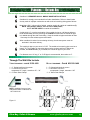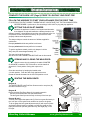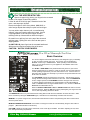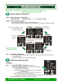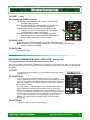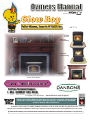
1
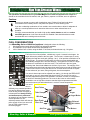
or
Memory & Fan Trim
TM
Step Top
Freestanding
Bay View
Freestanding
Bay View
Insert / Built-In
Classic Insert / Built-In
Toll Free Technical Support
1 - 866 - GLOWBOY (456 -9269)
To register your purchase
www.dansons.com/support
READ THIS ENTIRE MANUAL BEFORE YOU INSTALL AND USE YOUR HEATER.
FAILURE TO FOLLOW INSTRUCTIONS MAY RESULT IN PROPERTY DAMAGE,
BODILY INJURY OR EVEN DEATH!
Installation shall conform to CAN/CSA B365 Installation Code for Solid-Fuel-Burning Appliances and
Equipment in Canada and NFPA 211 Chimney, Fireplaces, Vents and Solid Fuel Burning Appliances in th e USA.
Contact local building or fire officials about restrictions and installation inspection requirement s in your area.
Dear Glow Boy Multi-Fuel / Pellet Stove Owner:
CONGRATULATIONS on the purchase of your Glow Boy Multi-fuel pellet appliance! You have
selected the finest in residential wood pellet heating technology.
Let us pass on a few "tips" concerning installing your stove and heating with wood pellets.
1. Whether you install your stove yourself or hire a professional installer, a quality installation
is a must for the safety of your family and for efficient, satisfactory operation of your stove.
2. Initial Burn Setup of the stove is the most important step to ensure the efficient and satisfactory
operation of your appliance for many years to come. Pellet appliances ARE NOT plug ‘n play.
3. Know the quality and characteristics of the pellets or fuel you burn. Pellets can vary greatly
from company to company, from load to load and occasionally from bag to bag.
4. Be extra diligent in your cleaning program.
5. Remember that most operational dilemmas with a pellet stove are usually traced back to
Improper installation, poor quality pellets and/or a lack of timely cleaning.
With just a minimum of daily care your Glow Boy pellet appliance will provide years of clean,
efficient, comfortable and environmentally sound heating.
Thank you for selecting a Glow Boy multi-fuel pellet appliance.
Sincerely,
Canadian Comfort Industries &
Dansons Inc.
UPDATES and REGISTRATION
Up to date additions, product information, product registration and warranty extension registration can
be found on our website www.dansons.com/support
COPYRIGHT NOTICE
Copyright 2009, Dansons Inc. All rights reserved.
No part of this manual may be copied, transmitted, transcribed, stored in a retrieval system, in any
form or by any means without the expressed written permission of,
Dansons Inc.; 14648 – 134th Ave,, Edmonton, AB, Canada T5L 4T4
Friendly Reminder:
A pellet stove / insert is not designed or tested as a primary source of heat. They are designed to
be a supplementary heat only, thus working together with your heating source.
Please do not disconnect or remove your existing primary heat source.
Glow Boy Pellet & Biomass
www.glowboystoves.com
22
TABLE OF CONTENTS
GENERAL INFORMATION
SAFETY PRECAUTIONS
SAFETY TESTING
HOW YOUR APPLIANCE WORKS
AUTOMATIC SAFETY FEATURES
SPECIFICATIONS
MAINTENANCE
4
5
6
7
8
ELECTRICAL REQUIREMENTS
PRE PLANNING
PLANNING & INSTALLATION CHECKLIST
9
10
33
2 TO 3 DAYS OR WEEKLY
PERIODIC MAINTENACE
34
1 TON, SEASONAL, BI-SEASONAL
FALL START-UP
SPRING SHUT-DOWN
35
35
YEARLY MAINTENANCE CONTRACTS
36
TROUBLE SHOOTING
REPLACEMENT PARTS
PLANNING EXHAUST SYSTEMS
TYPE
REQUIRED ROUTINE CLEANING
LIMITED WARRANTY
36
39
40
SAFETY PRECAUTIONS
DETERMING SIZE & DISTANCE
TERMINATION
PLANNING OUTSIDE AIR
APPLIANCE PLACEMENT
11
12
13
14
FLOOR PROTECTION
CLEARANCES TO COMBUSTIBLES
INSTALLATION
TOOLS OF THE TRADE
STEP BY STEP
DIRECT VENT INSTALLATION
MOBIILE HOME
INSTALLATIONS OPTIONS
FIREPLACE INSERT—MASONRY OR FACTORY
BUILD—IT—IN INSERT
16
17
18
19
20
22
OPERATION
BEFORE LIGHTING YOUR FIRST FIRE
USING THE ACUTRON CONTROLS
CHOOSING YOUR MODE OF OPERATION
24
25
26
MANUAL MODE
THERMOSTAT
MODES (OPTIONAL)
UNDERSTANDING YOUR ACUTRON CONTROL
LIGHTING YOUR FIRE
PERFORMANCE ENHANCEMENT TIPS
27
28
29
30
FUEL
WOOD PELLETS
CORN AND OTHER BIOMASS
Glow Boy Pellet & BioMass
31
32
www.glowboystoves.com
33
SAFETY PRECAUTIONS
IMPORTANT: Read, save and follow the instructions in this manual. It contains important safety, operating
and maintenance instructions you will need.
RECOMMENED: For your and your families protection and well being, Dansons’ highly recommends
installing and maintaining both a smoke detector as well as a CO2 detector.
•
BEFORE installing or having the pellet appliance installed contact the local building officials to obtain the
necessary permits and information on any installation restrictions or inspection requirements in your area
and notify your insurance company you have installed a pellet appliance.
•
This unit must be properly installed to prevent the possibility of a house fire. The instructions and local
building codes requirements must be strictly adhered to. Do not; use makeshift methods or material that
may compromise the installation.
•
When the pellet appliance is installed in a mobile home, the heater must be bolted to the floor, have outside air, and MUST NOT BE INSTALLED IN THE BEDROOM in accordance with the Manufactured
Home and Safety Standard (H.U.D), CFR 3280, Part 24. Check with local building officials.
•
NEVER try to repair or replace any part of the heater unless instructions for consumer are given in this
manual or instructed by Dansons Customer Service Department. A trained technician should do all other
work.
•
Educate all children of the danger of a high-temperature heater. Young children should be supervised
when they are in the same room as the heater.
•
This heater is designed and approved for pelletized wood fuel, shelled corn, or wheat only. Any other
type of fuel burned in this heater will void the warranty and safety listing. Keep foreign objects out of the
hopper.
•
NEVER use gasoline, gasoline-type lantern fuel, kerosene, charcoal lighter fluid, or similar liquids to start
or “freshen up” a fire in this appliance. Keep all such liquids well away from the appliance while it is in
use.
•
This heater must be connected to a standard 115 V., 60 Hz 3-prong grounded electrical outlet in accordance with local building codes, or in the absence of local codes, with the National Electrical Code, ANSI/
NFPA 70.
A grounded surge-protection unit is recommended.
•
Do not use an adapter plug or sever the grounding prong on the electrical plug.
•
Do not route the electrical cord underneath, in front of, or over the heater.
•
Do not unplug the stove if you suspect a malfunction.
Push the “OFF” Touch Pad and inspect the heater.
•
The heater will not operate during a power outage. If a power outage does occur, check the heater for
smoke spillage and open a window if any smoke spills into the room.
•
DO NOT operate the heater if you smell smoke coming from the heater. Push the “OFF” Touch Pad,
monitor your pellet appliance, and call your local authorized dealer.
•
Do not place clothing or other flammable items on or near the heater. When installed with a thermostat
there is a possibility of the heater turning on and igniting any items placed on or near the unit.
•
CAUTION: To prevent fingers, clothing or other objects from coming in contact with the auger; your appliance is equipped with a shutoff switch which stops the auger when the hopper lid is open. THE AUGER
IS CAPABLE OF CAUSING SERIOUS INJURY AND THIS SWITCH MAY NOT BE DISCONNETED.
Glow Boy Pellet & Biomass
www.glowboystoves.com
44
•
DO NOT operate the stove if the flame becomes dark and sooty or if the firepot overfills with pellets. Push
the OFF Touch Pad and inspect the heater. (See Operating Your Stove). Soot or creosote may accumulate in the exhaust vent system when the stove is operated under incorrect conditions such as an extremely rich burn. The flame will have a lazy orange color with black tips. This indicates poor pellet fuel
combustion.
•
NEVER block free airflow through the open vents of the unit. The viewing door and ash pan must be
closed and latched during operation.
•
The pellet appliance exhaust system works with negative combustion chamber pressure and a positive
chimney pressure, therefore the exhaust system must be completely airtight and properly installed. All
exhaust system vent joints must be sealed, gas tight, with HI-TEMP RTV silicone sealant, and/or at least
3 sheet metal screws per joint and to the heater also.
•
Your heater requires periodic maintenance and cleaning (Refer to ”Routine Cleaning” section of the
manual). Failure to maintain your heater may lead to smoke spillage in your home.
•
Disconnect the power cord from the electrical outlet before performing any maintenance. Pushing ”OFF”
Touch Pad does not disconnect all power to the heater.
•
BEFORE carrying out any maintenance or cleaning, allow the heater to cool. Ashes must be disposed in a
metal container with a tight lid and placed on a non-combustible surface or on the ground, well away from
all combustible materials, pending final disposal.
•
The exhaust system should be checked twice a year minimum for any build-up of soot or
creosote. Do not touch the hot surfaces of the heater.
NOTE: Canadian Comfort Industries grants no warranty, implied or stated, for the installation or
maintenance of your appliance, and assumes no responsibility of any consequential damage(s).
SAFETY TESTING
In accordance with the procedures and specifications listed in UL1482 – 1998 & ASTM E 1509-04, and
ULC-S627-00 and ULC-S628-M93 for solid fuel room heater. Tested and listed for use in Manufactured
Homes in accordance with Oregon Administrative Rules 814-23-900 through 814-23-909. The Canadian
Comfort Industries pellet stove has been independently tested and listed by INTERTEK (an accredited testing
laboratory) to UL, ULC and CSA standards. It is tested and listed for residential installation according to current
national and local building codes as:
•
•
•
•
•
A Freestanding Room Heater
A Fireplace Insert
A Built-in Insert
A Hearth Stove
A Mobile Home Heater.
The Safety Listing Label is located on the rear
inspection panel for model CCGB1 and CCGB2.
Please read the label carefully.
It contains important information
about installation and operation of your
pellet appliance.
Note that your STOVE’S serial number is located
on the safety label. Your appliance serial
Number is preceded by a “WH-“
(example WH-00000).
(see diagram)
Glow Boy Pellet & Biomass
www.glowboystoves.com
55
HOW YOUR APPLIANCE WORKS
The operations and maintenance of your Glow Boy Series of multi-fuel appliance are unique and
should not be considered to be like a wood, coal, gas, electric, propane or oil heater, stove or appliance.
Cautions:
Do not try to operate your stove with viewing door open. Pellets will not feed under these
circumstances and a safety concern may arise from sparks or fumes entering room.
If you are not drawing combustion air from outside, care must be taken to allow for adequate air
make up, to avoid possible room air starvation when stove or other exhaust fans are in
operation.
It is highly recommended that you install a high quality smoke detector as well as a carbon
monoxide gas detector in the room where stove is installed. Care should be taken to make
sure detectors are in working order at all times.
FUEL CONSIDERATIONS
Your Glow Boy Series of Multi-fuel appliance is designed to burn the following:
1.
Wood pellets that comply with the Pellet Fuel Industries standards.
2.
A combination of up to 50/50 Wood Pellet and Shelled Corn
3.
100% Shelled Corn or Grain, using the Multi—Fuel Grate, and manual start only, No Igniter.
Memory &
Fan Trim
as desired
Fuel in the form of wood pellets , shelled corn or grain is stored in the hopper. An
auger delivers the pellets to the burn grate. The fuel rate, or heat output, is set by
adjusting the feed rate touch pad, (settings 1 to 4). A fan provides combustion air to
the burn grate. The amount of combustion air in the burn grate is adjustable and
automatically changes as the fuel rate changes. The higher the fuel rate, the larger
the amount of combustion air and visa versa. The fuel burns in the burn grate,
producing heat. Some heat radiates out the front of your stove. The majority of the
heat passes around the heat exchange tubes and air plenum around the firebox and
is then moved into the room by the room air fan. A small amount of heat must pass
out the exhaust of your stove, along with gases, into the atmosphere.
Your stove's heat output can be adjusted from setting 1-4, through the FEED RATE
touch pad, to vary your heat output from Low to High. The room air fan can be
manually adjusted through the FAN SPEED to run faster or slower to correspond to
the amount of heat being produced. The room air fan is also on a limit switch,
controlled to run on high when the stove reaches higher temperatures and then
resume the speed you had selected once it cools to a lower temperature.
Your stove
can run
Heat Tubes
efficiently over extended periods of
time and at different heat output
levels as long as the fuel supply is
Tube Scraper
uninterrupted and timely cleaning
and maintenance is preformed.
Window
An example of how improper cleaning
effects operations is; the
exhaust pressure switch will shut the Burn Grate
pellet supply off and your stove will
Burn Pot
shut off if the exhaust system
becomes plugged.
Ash Pan
Glow Boy Pellet & Biomass
Hopper
Auger
Auger Motor
Exhaust
Air Intake
Fan Motors
www.glowboystoves.com
66
AUTOMATIC SAFETY FEATURES
L120 LOW LIMIT SWITCH
This limit switch is mounted on the exhaust blower housing and has 2 main functions:
Should the fire happen to go out, for any reason, this limit switch will shut the stove off when the exhaust
temperature drops below 120° F.
Upon starting the appliance, the AcuTron control board has a 15 minute “Lighting Mode”, if the stove
exhaust does not reach 120° F in that 15 minutes the stove will shut off. As soon as the stove
exhaust does reach 120° F, the limit switch opens and the AcuTron enters a 5 minute “Safety Delay”
mode.
F140 FAN LIMIT SWITCH
Your pellet appliance has a convection fan control limit switch. The room air fan's (F140) temperature limit
snap switch automatically operates the fan on high when your stove is producing heat faster than the fan is
carrying it into the room. This may occur when the heat control lever is set at [3 or 4] and the FAN SPEED is
set to a very low or off setting. After the fan runs at this automatic high setting a few minutes, it may cycle back
to its lower setting and may continue to cycle between [HIGH] and your selected setting. The circulation (room
air) fan cycling from high to low is a normal condition as well as a safety feature of your appliance.
To compensate for the fan cycling, adjust the FAN SPEED to a higher setting.
L250 HIGH LIMIT SWITCH
Your pellet appliance has a high temperature limit switch installed. If the temperature at the back of the firebox
reaches approximately 250° F., the switch will shut off the electricity going to the Vacuum Switch and to the
Auger Motor. The auger will automatically stop, and the appliance will shut down when the exhaust
temperature cools (120° F). If this happens call your dealer or Dansons Customer Service (1-866-456-9269).
IT IS IMPORTANT TO FIND THE REASON WHY THE UNIT OVERHEATED.
VACUUM SWITCH
This safety device (mounted on the back panel pillar) detects vacuum in the exhaust system, firebox, and air
intake. If the exhaust blower fails, the vent pipe becomes plugged, the viewing door is open, or if you are out
of pellets, this switch will sense that there is a lack of vacuum and will stop the auger from continuing to feed
pellets.
HOPPER LID SWITCH
Vac uum Switch
This device is mounted inside the
hopper.and is connected to the
auger feed system.……
If the hopper lid is OPEN the switch
WILL STOP THE AUGER FEED
SYSTEM. This is to prevent fingers,
clothing or other objects from
coming in contact with the auger.
High Lim it L 250
Low Lim it L1 20
Exha ust
The auger is capable of causing
serious injury and this switch
MAY NOT be disconnected.
Left Hand Side View
/ Exhaust Fan Side
Fan Lim it F 140
Air Intake
Co mb ustion Fan
AcuTron Wiring Harness
If the power does go out, the pellet appliance will stop running. When the power comes back
on, the stove will remember the function it was performing and return to that function.
Glow Boy Pellet & Biomass
www.glowboystoves.com
77
SPECIFICATIONS
HEATING SPECIFICATIONS
Approx. Heating capacity (sq. feet) *
Approx. Fuel burn rate per hour **
Hopper Capacity - Freestanding Step Top
Hopper Capacity— Classic Insert / Built-in
Hopper Capacity - Bay View Freestanding
Hopper Capacity – Bay View Insert / Built-in
800 – 2,000
1.5 – 5 lbs
90 lbs
40 lbs.
60 lbs
40—60 lbs.
Approx. Burn time at lowest setting
Approx. Burn time at lowest setting
Approx. Burn time at lowest setting
Approx. Burn time at lowest setting
65 hrs
27 hrs
48 hrs
27-48
¹ Heating capacity will vary depending on floor plan layout of your home, degree of insulation, and
the outside temperature. Fuel size, quality, density and moisture level will also have an effect.
¹¹ Pellet size may affect the actual rate of fuel feed and burn times. Fuel feed rates may vary by as
much as 20%. Use PFI listed fuel for best results, pelletheat.org for further information.
DIMENSIONS
26”
25”
24”
Shroud 1”
12 1/4”
7”
Exhaust
30”
Adjustable
Hopper
+
+
Air Inlet
6 ½”
19”
23”
17”
8 1/4”
26”
24”
10 3/4”
Exhaust
+
3 ½”
12 3/4”
24”
Bay View Freestanding
7 3/4”
8 1/4”
Air Inlet
Bay View Insert / Built-In
Shroud 1”
24 3/4”
24”
24”
+
12 1/4”
24 3/4”
24”
10 3/4”
6 1/2”
32 ½”
Exhaust
6 1/2”
+
+
Product subject to
Change without notice.
Exhaust
18 3/4”
+
17 1/4”
Air Inlet
8 1/4”
3 ½”
12 3/4”
24”
Step Top Freestanding
+
Air Inlet
7 3/4”
8 1/4”
Classic Insert / Built-In
ELECTRICAL SPECIFICATIONS
Electrical Rating
= 115 Volts 60 HZ 2.0 Amps
Watts (operational)
= 175 (approximately)
Watts (optional igniter)
= 475 (approximately)
A voltage surge protector or ground fault outlet is required for this unit. The warranty on the circuit
board will be voided if surge protection is not installed before operating this unit.
If power outages or disturbances are a concern, you may wish to purchase a gas powered generator,
solar or battery back-up system. Ensure that it is a “Positive” sign wave and a minimum 1000 watts
continual.
EPA COMPLIANCE
This heater is exempt from EPA Phase II requirements, but has been tested for emissions using EPA test
methods by Warnock Hersey , US. Pellet appliances that are designed with the combustion air supply
exceeding 35:1 (by ratio) are exempt from EPA regulations.
Glow Boy Pellet & Biomass
www.glowboystoves.com
88
PLANNING & INSTALLATION CHECK LIST
Unless you are knowledgeable and experienced in stove installation, we recommend your Glow Boy Appliance
receive a Pre-delivery Check and be installed by your local Specialty Retailer, NFI (National Fireplace Institute)
Pellet Specialist (USA) or WETT Certified Installer (CAN) .
COMPLETE THIS CHECK LIST PRIOR TO INSTALLING YOUR MULTI-FUEL APPLIANCE:
_____
Carefully read this "Owners Manual”. SAVE THIS MANUAL.
_____
Have your local Dealer demonstrate all the operational, cleaning and maintenance steps
necessary for your stove.
_____
Select a location. The design of your home and the stove placement will determine its value
as a source of heat. A pellet appliance depends primarily on air circulation to disperse its
heat. There are other practical considerations, which must be considered before a final
placement is decided on:
Existing Chimneys, Pellet Fuel Storage, Aesthetic Considerations, Roof Design (rafter
locations & roof pitch), Room Traffic, Clearances to Combustibles, and Existing Wiring.
_____
The installation of this appliance must conform to local codes and applicable state and
federal requirements. Becoming familiar with these requirements before installation is
essential.
_____
Sign and keep a copy of the Pre-delivery Check List supplied by your Authorized Dealer, OR
“Dansons Certified Installer”, found inside our appliance or available online.
______ Attach your proof of purchase to this manual and keep on hand for warranty.
COMPLETE THIS CHECK LIST WHILE INSTALLING YOUR MULT—FUEL APPLIANCE:
_____
Carefully read the ENTIRE installation section first. Twice is better.
_____
Read the Installing Freestanding, Insert or Built-In sections.
_____
Determine the location and measurement needed your chosen location.
_____
Be sure to pre-fit all items before you install, fasten or install the stove permanently.
Remember measure twice, cut once.
_____
Ensure ALL joints of “PL” vent and single wall stainless steel liner are tightly connected,
sealed with RTV Silicone or Hi-Temp foil tape, including to the exhaust connector, and
is correctly installed. (Follow vent manufacturer’s instructions.)
COMPLETE THIS CHECK LIST PRIOR TO LIGHTING YOUR FIRST FIRE:
_____
Obtain final inspection and approval by local building officials.
_____
Carefully clean all marks off the brass, nickel or pewter parts before the first fire is lit. Use a
soft cloth and a gentle type cleaner. Caution: Never use an abrasive cleaner on any part of your
stove.
_____
Polish the hopper to remove the oil type coating used in manufacturing.
_____
The high temp. stove paint used on your stove may take several hours of burning at a high fuel
setting to fully cure. During this time an odor, which is not harmful, may be evident. The area
around the stove should be well ventilated.
_____
Review and follow the Lighting and Controls Instructions.
_____
Ensure that appliance is connected to a surge protection unit.
_____ Fill the hopper with quality pellets, Close the Hopper Lid, Using the CCI “AcuTron”,
(figure 5), PUSH the FEED RATE Touch Pad and this will start the auger and the combustion fan.
Glow Boy Pellet & Biomass
www.glowboystoves.com
99
PLANNING—EXHAUST SYSTEMS
PELLET VENT MUST MAINTAIN A MINIMUM 3” CLEARANCE TO ANY COMBUSTIBLE
(INSTALL VENT AT CLEARANCES SPECIFIED BY THE VENT MANUFACTURER).
DO NOT CONNECT THE PELLET VENT TO A VENT SERVING ANY OTHER APPLIANCE OR
STOVE.
DO NOT INSTALL A FLUE DAMPER IN THE EXHAUST VENTING SYSTEM OF THIS UNIT.
PELLET VENT TYPE:
1.
Must be an approved 3” or 4” Diameter Type ”PL” vent, vented to the outside (fig. 7) or connect
the vent to a factory built type “A” chimney using an adaptor.
2.
Exception: A single wall “All Fuel” Stainless Steel chimney liner may be used inside a fireplace
or fireplace installations (fig. 8) .
3.
Some venting manufactures do make “PL” vent for use with wood pellet fuel only and another
type of “PL” vent for corn or bio mass fuels. If in doubt, plan for the future and use the corn or
multi-fuel
4.
Use 4” dia. vent if vent or liner height is over 15’ or if installation is over 3.000’ above sea level.
NOTE: 4” diameter vent may be used in all installations. If in doubt, use 4” dia. vent.
VENT SAFETY PRECAUTIONS:
A “Clean Out Tee” (4) must be installed at the bottom of all vertical runs. These “Tee’s” are to
assist in periodically cleaning the vent. Single or Double clean out tees may be used. The exhaust
system must be installed so the entire system can be cleaned without disassembly.
Termination must exhaust above the fresh air inlet
elevation, and parallel or above the exhaust output
of the multi-fuel appliance.
It is highly recommended that at least 3 feet of vertical
pipe (5) be installed to create some natural draft. This is
to help prevent the possibility of smoke or odor during
the appliance shut down.
7
Horizontal sections must have a 1/4” rise every 12” of
travel after 3’ long.
Pellet vent connections must be sealed gas tight. Use
Hi-Temp RTV Silicone, good for over 600° F or Hi-temp
Metal foil tape, that meets UL181 standards,. DO NOT
use “Duct Tape”.
Seal each vent section by injecting a liberal amount of
sealant into the gap and/or wrap with foil tape.
It is strongly recommended that the exhaust system
be terminated on the prevailing wind side of the home.
6
9
5
1
4
2
3
Appliance may not be placed in, or vented through
a gas fireplace.
Glow Boy Pellet & Biomass
8
www.glowboystoves.com
10
10
PLANNING— EXHAUST SYSTEMS
… CONTINUED
DETERMINE VENTING SIZE AND DISTANCE:
It is recommended that the vent system be installed with a minimum of three (3’) of vertical
rise above the appliance exhaust port.
Equivalent Vent Length (EVL) is the method of determining vent sizes and lengths, that takes into account the
effect of different component parts on air flow.
STEP 1
To help you determine the correct size and/or run, simply fill in the chart below.
Pellet Venting
Component
# of Elbows
OR feet of Pipe
Multiply by
Equivalent
Feet
90 Degree or Tee
X
5
45 Degree
X
3
Horizontal Pipe
X
1
Vertical Pipe
X
.5
Component
Equivalent
Step 2
Ensure the Total Equivalent is or is
less than 30.
Step 3
Use the Sizing Chart to determine
the proper venting size according to
the Total Equivalent and the
Altitude above sea level.
NOTE:
Equivalent Pipe Length in Feet
Total Equivalent
30
4 Inch Diameter Only
20
10
3 or 4 Inch Diameter Pipe
In some cases it may be necessary
0 1 2 3 4 5 6 7 8
to contact Dansons Customer
Altitude in Thousands of Feet
Service personal to determine
acceptable venting
Maximum venting height is 33’.
configurations
Maximum horizontal offset is 10’.
and altitude adjustments
1-877-303-3134.
The diagram to the right will help to
give you a visual reference.
9 10
33’
30’
Use the Equivalent Vent Length
Chart to determine proper
combination of component parts.
Vent must have a support
bracket every 5’ when on
the exterior wall.
Use 4” Diameter “PL” Vent
If venting outside of
shaded area.
Vent height and run must
not exceed the distance
shown in the un-shaded
region of chart.
Use 3” or 4” Diameter
“PL” Vent, if venting in
shaded area.
25’
20’
15’
To achieve optimum
performance, keep vent runs
as short as possible.
Especially on horizontal
installations.
10’
5’
0’
0’
Glow Boy Pellet & Biomass
5’
www.glowboystoves.com
10’
11
11
PLANNING— EXHAUST SYSTEMS … CONTINUED
PELLET VENT TERMINATION: (Figures 7 & 8)
Termination must be a minimum of 12” above the chase cap (B) (note: the chimney must meet local codes for height above the roof or
B
other obstructions)
B
Must have an approved cap (G) (to prevent water from entering) or a 45* elbow downturn (F)
If the termination is located on a windy side of house, an
approved house shield is recommended to prevent soot
from accumulating on the side of the house.
A
A
Must not be located where snow or other materials such as
leafs, snow or grass, could block it.
Must have a “Metal Seal Plate” or “Wall Thimble” at point
(A)
Figure 7
Figure 8
VENT TERMINATION CLEARANCES:
NOTE: Horizontal terminations must protrude 12” from the wall, vertical terminations 24”
Inside Corner
Detail
I
E
x
3’
2’
10’
A
B
C
D
E
F
G
H
I
X
Minimum 4’ clearance below or beside any door or window
which opens.
Minimum 1’ clearance above any door or window that opens.
Minimum 3’ clearance from any adjacent building.
Minimum 7’ clearance above any grade when adjacent to public walkways.
Minimum 2’ clearance above any grass, plants, or other combustible material.
Minimum 1’ clearance above grade.
Minimum 3’ clearance above any forced air intake of any other appliance within 6’.
Minimum 2’ clearance below eves or overhang.
Minimum 1’ clearance horizontally from combustible wall.
Minimum 1’ clearance to inside corner
Must be a minimum of 36” above the roof and 24” above the highest point of the roof within 10’.
NOTE: The following are not found on the above diagram.
•Minimum 3’ above a gas meter/regulator within 3’ horizontally of the vertical centre line of regulator.
•Minimum 6’ clearance to a gas service regulator vent outlet.
•Minimum 1’ clearance under veranda, porch, deck or balcony. Permitted only if structure is fully
open on a minimum of two sides beneath the floor.
Glow Boy Pellet & Biomass
www.glowboystoves.com
12
12
PLANNING— OUTSIDE AIR
Outside air is REQUIRED ON ALL MOBILE HOME INSTALLATIONS.
Outside air is strongly recommended for all other installations. Failure to install intake
air may result in improper combustion as well as the unit smoking during power failures.
Metal pipe, ONLY, either solid or flexible, must be used in all outside air installations.(B)
NOTE: Non-metallic material, such as PVC or ABS plastic,
MUST NOT BE USED for outside air installations.
A wind shield, (C), over the termination of the outside air pipe or a 90 degree elbow or
bend directed away from the prevailing winds MUST be used when an outside air pipe
is in-stalled through the side of a building. Keep the outside air pipe termination at least
1 foot away from the exhaust system termination.
When outside air is taken from an existing chimney, the exhaust system must not
terminate in the same chimney.
The outside air pipe on your stove is 2" OD. The outside air connecting pipe must be at
least 2" ID The outside air connecting pipe must be as short and free of elbows as
possible, and must fit over, (A), not inside, the outside air pipe on your stove.
For distances over 10’ long, 3” or 4” OD pipe is recommended, then reduce to 2”.
Through The Wall Kits Include:
3 FOOT PACKAGE – PART# 5150-1450
10 FOOT PACKAGE – PART# KS5150-1460
1 – 2” Galvanized Hood c/w screen
1 – 2” Aluminum Flex Duct –
compressed 15” length, extends to 30” – 36”
2 – 2” Worm Gear Clamps
1 – 2” Galvanized Hood c/w screen
1 – 2” Aluminum Flex Duct –
compressed 4’ length, extends to 120”
2 – 2” Worm Gear Clamps
NOTE: Available from your local
Authorized Dealer or Dansons Inc.
1-877-303-3134
Figure 11
Glow Boy Pellet & Biomass
www.glowboystoves.com
13
13
PLANNING— PROTECTION & CLEARANCES
STOVE PLACEMENT:
Stove must be placed so that no combustibles are within, or can swing within (i.e. drapes doors),
36” of the heater.
Keep in mind the following placement concerns; venting obstructions, outside air, electrical
outlet, wall thermostat, heat distribution, traffic patterns and room use/size.
If the stove is placed in a location where the ceiling height is less than 7’, it must follow the
requirements in the section “Alcove Installation”.
FLOOR PROTECTION REQUIREMENTS:
Stove and floor protection must be installed on a level secure floor
NOTE: It is important for your appliance to be level. Leveling should occur below the floor
protection pad.
The stove must be installed on a continuous (grouted joints) non-combustible floor protector
such as ceramic tile, cement board, brick, 3/8” millboard or equivalent, or other approved or
listed material suited for floor protection.
THE MATERIAL(S) USED MUST HAVE, OR COMBINE TO HAVE, A MINIMUM INSULATIVE
RATING OF “R1”.
Must extend 6in (300mm) beyond the front of the stove as well as 6 in (300mm) beyond each
side of the fuel loading and ash removal opening(s)
Must extend under and 2” to each side of chimney tee (if used).
MINIMUM CLEARANCES TO COMBUSTIBLES:
2” From Back Of Stove to Combustibles
Figure 10—15
3” From PL Vent to Combustibles
2” From Side of Stove to Combustibles
2” From Back Corner of Stove to Combustibles
16” From Top Of Stove to Combustibles
6” Non Combustible Surface In Front Of Heater
36” to drapes, doors, anything that can swing
NOTE: Although not required for safety reasons, it is strongly suggested that sufficient space be provided
(a minimum of 24”) on each side of the appliance and at the back of the appliance to enable servicing the unit
if necessary. If this space is unavailable, a provision must be made to enable sliding the appliance out.
CLEARANCES – “STRAIGHT INSTALLATION”:
THROUGH T HE W ALL
INTERIOR V ERTICAL
12”
1”
3”
2”
10”
6”
6”
6”
6”
Glow Boy Pellet & Biomass
6”
6”
6”
www.glowboystoves.com
14
14
PLANNING— PROTECTION & CLEARANCES . . . CON’T
CLEARANCES – “CORNER INSTALLATION”:
45 CORNER
THROUGH T HE W ALL
45 CORNER
INTERIOR
V ERTICAL
12”
3”
2”
6”
6”
6”
6”
6”
6”
Figure 12
Figure 13
Note: If interior vertical vent is used (figure 13), the clearance to the back wall is determined by the
upward-turned “Clean Out Tee”. It will vary in depth depending on the brand of PL vent used.
Before placing the stove, connect the “Tee” and measure off the 3” clearance.
ALCOVE INSTALLATION:
Minimum clearances to combustibles:
2 inch from back of appliance
16 inches from the top
(Figure 14 & 15)
10 inches from the sides
30 inches deep
ALCOVE - THROUGH THE WALL
12”
1”
2”
16”
10”
6”
6”
6”
6”
Figure 14
Glow Boy Pellet & Biomass
Figure 15
www.glowboystoves.com
15
15
TOOLS REQUIRED
Before starting your Glow Boy Multi-Fuel install, we recommended you have the following list of tools ready.
This is not an exhaustive list, but should go along way in making your installation easier.
Power Tools
Shop Vacuum WITH Filter
Jigsaw or Reciprocating saw
Electric drill
Extension cord
4” or 5” diameter coring bit and drill
(if going through concrete)
Hand Tools
Tape Measure
Caulking Gun
Circle Maker
Allen (Key) wrench set
Stud Finder
Set of sockets or nut driver 1/4”, 5/16” and
7/16”
Assortment of Phillip, Robertson and slot
screwdrivers
Assortment of sheet and wood drill bits
Flashlight
Wire stripper and wire cutter
Hammer
Bubble Level
Utility knife
Adjustable pliers (6 to 8 inches)
Small hand broom and dustpan
Furniture and Floor Protection
Supplies
Caulking tube of RTV Hi-Heat Silicone
Caulking tube of Clear Silicone
Hi–Heat Aluminum Foil Tape
2” long Wood screws (10+)
Assortment of sheet and wood screws
“Stove Bright” Hi-Heat Stove Paint
Glow Boy Pellet & Biomass
www.glowboystoves.com
16
16
INSTALLATION—FREESTANDING
THROUGH THE WALL, DIRECT VENT INSTALLATION.
1.
Position the floor pad.
3.
Following the "PL" vent manufacturer's specifications, mark and cut a hole through the wall to
accommodate the wall thimble, (F), and the outside air pipe, (I), if outside air is to be used. Remember that the outside air intake must be located no closer than 12” from the vent exhaust.
Try to avoid cutting wall studs, and use extreme
caution to avoid cutting into power or water lines
within the wall of your home.
4.
Install the wall thimble, (F). Be sure to run a bead
of silicone around the outside edges of the wall
thimble to reduce drafts, both inside and outside.
Insert the proper size of "PL" vent, (E), through
the wall thimble, (F).
(Figure 18)
THROUGH THE WALL
Select the location for your stove, design the
exhaust system and determine the brand and
size of "PL" vent to be used.
2.
(not preferred)
12”
1”
2”
10”
6”
6”
6”
6”
5.
Place your stove on the floor pad, close to its final position. Leave room to connect the "PL" vent to
“Quick Connect” end collar. If not already factory installed, Install the gasket (B) and “Quick Connect”
exhaust end (C) to your stove to the “Quick Connect” mounting plate. Use the 4 x 7/16” nuts, supplied
and secure tightly.
6.
Place a bead of RTV silicone around the end collar of the “Quick Connect” of your stove's exhaust, (C).
Firmly push the “PL” vent pipe adaptor (J) into the bead of RTV silicone.
Note: If 4" PL vent is required, use an 3” to 4” Pipe Adaptor Increaser, (J), on the stove exhaust pipe.
7.
Connect the length of "PL" vent, (E), that is in the thimble, (F), onto the pipe adaptor (D). Fasten
together with at least three sheet metal screws (approx. 3/8” in length). Place a bead of RTV silicone
around the connection.
8.
Place your stove in its final position on the pad. Place another bead of RTV silicone around the “PL”
vent (E) and the inside of the wall thimble, to stop cold air drafts.
9.
On the outside of the building, place an exhaust cap (G) or a 45 degree "PL" type elbow, (G), onto the
end of the horizontal "PL" vent, (E). Optionally, place a rodent screen cap, (G), (may be required in
some locals), on the end of the elbow, (G). run a bead of RTV silicone around all connections and
around the “PL” vent pipe and the outside of the wall thimble.
Note: The end of the exhaust pipe must extend a minimum of 12” from the outside of the building.
Note: Most horizontal, through the wall installations may require a Clean-out Tee and minimum 3’
vertical rise of pipe, inside or outside the building.
See Next Page.
Glow Boy Pellet & Biomass
www.glowboystoves.com
17
17
MOBILE HOME INSTALLATION
CAUTION: DO NOT INSTALL STOVE IN SLEEPING ROOM
THE STRUCTURAL INTEGRITY OF THE MANUFACTURED HOME FLOOR,
CEILING and ROOF MUST BE MAINTAINED!
Your Glow Boy appliance has been tested and listed for mobile home installation. It may be
installed in a mobile home as a "Free Standing Stove" or a "Hearth Stove", see detailed install and
clearance requirements in these sections as they imply there.
In addition to all previously detailed installation requirements, mobile home in-stallations
must meet the following requirements in accordance with the Manufactured Home and
Safety Standard (HUD) CFR 3280, Part 24:
Permanently bolt your stove to the floor, (A), figure 25.
Electrically ground your stove or the pedestal to the steel frame of the home. Use a number 8 gauge
copper wire, (B), figure 25, or equivalent.
The stove must have a permanent outside air source with a ¼ inch screen over the inlet.
Figure 26, (B, C & D)
For transportation all chimney/vent above the mobile home must be removed.
Chimney/PL Vent must be 3” or 4” PL Vent and must extend a minimum or 36” above the roofline
of the mobile home and must be installed using a UL / ULC listed ceiling fire stop (J), figure 26,
and rain cap (L), figure 26., when installing as a vertical run. See diagram below.
REFER TO THE VENTING DIAGRAMS IN THIS MANUAL FOR FURTHER EXHUAST CONFIGURATIONS.
INSTALL VENT AT CLEARANCES SPECIFIED BY THE VENT MANUFACTURER.
A
Floor Pad
B
C
D
E
Combustion Air Intake
Fresh Air Duct
Fresh Air Hood
Stove Exhaust
F
Pipe Adapter
G
H
Clean Out Tee
Tee Support Bracket
I
J
Pipe
Firestop Spacer / Ceiling Support
K
Roof Flashing / Storm Collar
L
Rain Cap
L
K
J
I
H
G
HEARTH PAD
A
FLOOR
B
GROUND
WIRE
BOLT(S)
FRAME
B
C D
A
Figure 25
Figure 26
Note: When moving your mobile home, all exterior venting must be removed. Upon completion of relocation,
all venting must be reinstalled, gas tight, and securely fastened.
Glow Boy Pellet & Biomass
www.glowboystoves.com
18
18
FREESTANDING INSTALLATION
. . . CON’T
These styles of installation are highly recommended, due to possible backpressure in the exhaust caused by
airflow around the outside of the structure, snow build-up, or power failure, etc.. These designs will improve
venting performance and provide natural draft to help evacuate smoke from the appliance in case of power
failure.
Follow the same basic steps in locating your appliance, attaching the exhaust system and outside air intake to
your stove as the previous examples.
Floor / Ceiling
9
10
8
Basement or Main Floor
7
12”
5
Ground Level
4 Clean Out Tee & Cap
5 12” Pipe Length
6 12” Adjustable Pipe Length
5 36” Pipe Length
6 Tee Support Bracket
7 90 Deg Elbow
8 Wall Thimble
7 90 Deg Elbow
9
9
4
3
Pipe Adapter
2 12” Pipe Length
3 12” Adjustable Pipe Length
1
3 Tee Support Bracket
4 36” Pipe Length
6
12”
Walkout Basement or Main Floor
1 Pipe Adapter
2 Clean Out Tee & Cap
24” Pipe Length x 2
8
9 Wall Thimble
10 Horizontal Rain Cap
Tube of RTV Silicone
Roll of Foil Tape
3/8” Stainless Self-Tapping
Screws x 27
2” Wood Screws x 10
1
7
8 Horizontal Rain Cap
Tube of RTV Silicone
Roll of Foil Tape
3/8” Stainless Self-Tapping
Screws x 21
2” Wood Screws x 10
6
Options
9
1
5
2
4
2
3
8
7
6
1
5
9
Pipe Adapter
1
Pipe Adapter
2 Single Wall Stainless Steel
Clean Out Tee & Cap
2
Clean Out Tee & Cap
3 Dripless Connection
3
3 x 60” (15’) Pipe Length
4 “All Fuel” Stainless Steel
Flex Liner
4
Tee Support Bracket
5
Ceiling Support / Firestop Spacer
6
Roof Flashing
5 Liner Support
6 Roof Flashing
7 Storm Collar
8”
8
Vertical Rain Cap
9
Hi Heat Insulation
10 PL Vent Length
16”
Optional
Metal Plate
Tube of RTV Silicone
Roll of Foil Tape
3/8” Stainless Self-Tapping
Screws x 27
4
1
10
3
2
Main Floor - Vertical
Hearth Stove - Existing Reline
24”
7 Storm Collar
8
7
6
5
8 Vertical Rain Cap
Tube of RTV Silicone
Roll of Foil Tape
3/8” Stainless Self-Tapping
Screws x 27
4
3
2” Wood Screws x 10
1
6”
2
Outside Air may be obtained from a suitable duct passing through the
ash clean-out opening.
Ensure the chimney top is properly sealed to prevent intrusion of
weather and down drafts with suitable flashings, collars, and sealants.
Glow Boy Pellet & Biomass
www.glowboystoves.com
19
19
FREESTANDING INSTALLATION
11
10
9
24”
8
7
6
Main Floor - Class A Tie-In
Main Floor - Tie-In Claytile Flue
1 “PL” Pipe Adapter
2 “PL” Clean Out Tee & Cap
3 “PL” Length of Pipe
4 “PL” 90D Elbow
5 “PL” Wall Thimble
6
Single Wall Stainless Steel
Clean Out Tee & Cap
5
Cleanout
Door
2
1
Pipe Adapter
2
Clean Out Tee & Cap
3
3 x 60” (15’) Pipe Length
Tee Support Bracket
11
7
“PL” Adjustable length
“PL” to Class A Adaptor
6
4
5
6
Dripless Connection
8
“All Fuel” Stainless Steel
Flex Liner or “PL” Venting
7
Ceiling Support / Firestop Spacer
Roof Flashing
Liner Support
8
Roof Flashing
9
9
10
Storm Collar
11
12
Vertical Rain Cap
Hi Heat Insulation
Tube of RTV Silicone
Roll of Foil Tape
3/8” Stainless Self-Tapping
Screws x 27
9
1
7
4
3
. . . CON’T
8
5
Class A Fittings
Storm Collar
10 Vertical Rain Cap
11 Lengths of Pipe
10
3
Tube of RTV Silicone
4
1
2
Roll of Foil Tape
3/8” Stainless Self-Tapping
Screws x 27
Outside Air
Intake
FIREPLACE INSERT INSTALLATION
The Glow Boy Series Multi-Fuel Inserts may be installed in either a masonry or factory built fireplace.
Installing Pellet Inserts into Factory Built or Masonry Fireplaces:
The insert must be tested and meet the requirements of UL1482 (US) and or ULC8628 (CAN) when
Tested in a masonry fireplace built per ULC S628.
The factory-built fireplace must be listed per UL127 or ULC8610.
Clearances obtained from the masonry fireplace tests are also relevant for installation in factory-built
fireplaces.
Installation must include a full height listed chimney liner meeting type HT requirements (2100D F)
per UL1777 (US) or ULC 8635 (CAN). The stainless steel liner must be securely attached to the insert
flue collar and the chimney top.
Means must be provided to prevent room air passage to the chimney cavity of the fireplace. This may
be accomplished by sealing the damper area around the chimney liner.
The airflow within and around the fireplace shall not be altered by the installation of the insert (i.e. no
louvers or outlet ports are blocked), unless specifically tested as such for each factory-built fireplace
manufacturer and model line.
NOTE: using a louvered faceplate (surround) complies with this requirement.
Alteration of the fireplace in any manner is NOT permitted with the following EXCEPTIONS:
1.
External trim pieces which do not affect the operation of the fireplace my be removed
Providing they can be stored on or within the fireplace for re-assembly, if the insert is
removed.
2.
The chimney damper may be removed to install the chimney liner.
Circulating air chambers (i.e. in a steel fireplace liner or metal heat circulator) shall not be blocked.
Glow Boy Pellet & Biomass
www.glowboystoves.com
20
20
FIREPLACE INSERT INSTALLATION
Installing Pellet Inserts into Factory Built or Masonry Fireplaces
. . . cont
Means must be provided for removal of the insert to clean the chimney liner.
Inserts that project in front of the fireplace must be supplied with appropriate supporting means.
A permanent metal warning label must be attached to the back of the fireplace stating that the
fireplace must be restored to its original condition for safe use without the insert.
This sticker is supplied in the “Owners Manual” and accessories packaging, found in the unit.
(See the following statement)
THIS FIREPLACE HAS BEEN ALTERED TO ACCOMMODATE A FIREPLACE
INSERT AND SHOULD BE INSPECTED BY A QUALIFIED PERSON PRIOR TO
RE-USE AS A CONVENTIONAL FIREPLACE!
When installing into a masonry chimney, it is recommended that the exhaust vent be extended to
the top of the chimney as shown in figure 26.
However, if the vent pipe does not extend to the top of the chimney, the pipe must extend a
minimum of 18” above the damper.
You must seal the damper area with a steel plate when using the direct connection method.
FULL CHIMNEY RELINE
Note: This installation is recommended
for all chimney installations!
DIRECT CONNECTION
Note: This installation not allowed in Canada
8”
6”
Glow Boy Pellet & Biomass
8”
6”
www.glowboystoves.com
21
21
BUILT-IN INSTALLATION
CAUTION: DO NOT BLOCK ANY VENT OPENINGS
PELLET VENT MUST MAINTAIN A MINIMUM 3” CLEARANCE TO ANY COMBUSTIBLE.
(INSTALL VENT AT CLEARANCES SPECIFIED BY THE VENT MANUFACTURER).
DO NOT CONNECT THE PELLET VENT TO A VENT SERVING ANY OTHER APPLIANCE OR
STOVE.
DO NOT INSTALL A FLUE DAMPER IN THE EXHAUST VENTING SYSTEM OF THIS UNIT.
THE APPLIANCE MUST BY PLACED ON A NON-COMBUSTIBLE SURFACE,
BOTH ON THE HEARTH AND WITHIN THE FRAMED AREA.
(REFER TO FLOOR PROTECTION REQUIREMENTS IN THIS MANUAL.)
The Glow Boy Series Inserts may be framed directly into a wall as either a horizontal or vertical vent
installation. (see figure 27, 28).
The exhaust installation requirements are the same as for a freestanding stove. Refer to
“Installing Freestanding Stove” for information concerning installation and proper hook-up of the exhaust.
NOTE: Built-in Installations require: Enclosure Spacer Kit — #ACI-3HZ Horizontal Kit or ACI-3VL Vertical Kit
Shroud 1”
12 1/4”
Shroud 1”
12 1/4”
24 3/4”
24”
10 3/4”
26”
24”
10 3/4”
Adjustable
Hopper
6 1/2”
19”
23”
Exhaust
18 3/4”
+
3 ½”
24”
Air Inlet
8 1/4”
Classic Step Top Insert / Built-In
Glow Boy Pellet & Biomass
Exhaust
+
3 ½”
7 3/4”
+
6 ½”
24”
+
Air Inlet
7 3/4”
8 1/4”
Bay View Insert / Built-In
www.glowboystoves.com
22
22
BUILT-IN INSERT INSTALLATION
. . . CON’T
MINIMUM FRAMING DIMENSIONS:
The MINIMUM framed opening or clearances to all combustibles are as follows:
(Combustibles include drywall or any paper backed product, wood framing, insulation, vapor barrier, or any
other product as set out in our local building code.)
Minimum
Required
Traditional
Unit Only
Traditional
Minimum
BayView
Unit Only
Bayview
Minimum
Side Clearance
3 in
22 1/4 in
28 1/4 in
24 in
30 in
Top Clearance
2 in
18 3/4 in
20 3/4 in
19—23 in
25—29 in
Back Clearance
6 in
11 3/4 in
17 3/4 in
10 3/4 in
16 3/4 in
Note: The BACK frame distance will be effected by the depth of the framed wall as well as the installation of
the exhaust venting.
Exterior Wall
TIP:
To allow for much
easier removal of the
appliance and for cleaning and maintenance , it
is highly recommended
to make your framed
opening as large as
possible. It is suggested
to use your overall
Shroud Enclosure
measurements and
construct your framing to
be 1 to 2 inches smaller
than the shroud.
Horizontal Vent Installation
Exterior Wall
2’
Wood Frame
Construction
10’
8”
2” Min.
Air gap
8”
Shroud
Wood Frame
Construction
2” Min.
Air gap
6”
Wall Band /
Support Brkt
every 5’
Shroud
6”
6”
4
6”
4
Clean Out Tee
12”
Wood Surround
Stand Offs
Part ACI-3HZ
Wood Surround
Stand Offs
Part ACI-3HZ
Vertical Vent Installation
Interior
2’
Vertical Vent Installation
Chase
Rain Cap
Storm Collar
10’
When constructing a chase
ensure adequate insulation,
vapor barrier, drywall and
caulking is used. Keep in
mind you are building
another room to your home.
You want it to be as energy
efficient as the rest of your
home.
3” minimum
air gap
Metal
Chase Cap
Ceiling Support /
Firestop Spacer
Ceiling Support /
Firestop Spacer
Wood Frame
Construction
8”
Wood Frame
Construction
8”
Wall Band /
Support Brkt
every 5’
Shroud
Wall Band /
Support Brkt
every 5’
Shroud
3” minimum
air gap
6”
3” minimum
air gap
6”
Clean Out Tee
Wood Surround
Glow Boy Pellet & Biomass
Stand Off
Part ACISOVL
Clean Out Tee
Wood Surround
Stand Off
Part ACISOVL
www.glowboystoves.com
23
23
OPERATING INSTRUCTIONS
COMPLETE THE CHECK LIST (Page 9) PRIOR TO LIGHTING YOUR FIRST FIRE
FOLLOW THE ARROWS TO START YOUR APPLIANCE FOR THE FIRST TIME
IT IS CRITICAL FOR THE CORRECT OPERATION OF YOUR STOVE THAT THE FOLLOWING STEPS
BE PERFORMED! A pellet stove, like most things is life is NOT a plug and play appliance.
SETTING THE AIR INLET DAMPER
Because the appliance is made in one location and elevation,
then shipped, moved and installed to a different location, at a
different elevation, vented differently and then using different fuels. It is
not possible for the manufacture to factory set your stove to work
properly without some adjustments.
The damper helps to control the amount of airflow supplied for
combustion.
Damper pushed in all the way airflow is minimum.
Damper pulled out all the way airflow is increased.
To get the appliance started, push the air damper in all the
Way, then pull outward approximately 1/2”.
This may not be the final setting.
We will cover FINE TUNNING YOUR STOVE later in this manual.
OPENING AND CLOSING THE MAIN DOOR:
Open the stove door by rotating the handle COUNTER
CLOCKWISE, toward the TOP of the stove, until the handle is
about the 3 o’clock position. Swing door open to the
left.
Close the stove door by keeping the handle at the
3 o’clock position. Push the door firmly against the stove.
Rotate the handle downward to the 6 0’clock position to lock.
B
SEATING THE BURN GRATE:
G
C
Diagram A
The SUPER GRATE multi-Fuel Burn Grate comes in one piece: (B)
and sits in the Burn Pot (A)
A
Diagram B
Ensure the Multi-Fuel Burn Grate (A) is properly seated in
the burn pot and holes are free from obstructions .
The burn grate front lip must sit firmly on the top of the burn pot.
Diagram A
Diagram B and C
You may need adjust the spacer tab (C) if the burn grate fits loosely in
the burn pot or if the Igniter hole needs to be closer to the igniter.
To do so grasp the burn grate adjustment tab (C) with a pair of pliers
and bend it slightly inward or outward, until the burn grate top rest
tightly onto the burn pot and grate fits firmly, with slight play, in the
burn pot.
C
Diagram B
Glow Boy Pellet & Biomass
Diagram C
www.glowboystoves.com
24
24
OPERATING INSTRUCTIONS
FILL THE HOPPER WITH FUEL:
Open the hopper lid by placing your fingers in the recessed
handle on the hopper lid and lifting upward.
Lift the lid until the lid is fully open, toward the back of the
stove, and stays open by itself.
Ensure the hopper is clean of any debris, MANUALS, or
other foreign objects that could jam up the fuel feed auger.
You may wish to wipe clean any oils, or manufacturing
leftovers, using any cleaning agent and a cloth. As well
a light application of car wax to the hopper will aid in
reducing build-up of dust and fines within the hopper.l
Be careful not to spill any fuel on the top of the stove and
adjoining gaps. Spilling fuel on the floor can also pose a
slipping hazard.
CLOSE THE LID, place finger into the recessed handle and
With control, pull the lid toward the front of the stove.
CAUTION: WATCH YOUR FINGERS.
II or III w/Memory& FanTrim
Basic Overview
Memory &
Fan Trim
The AcuTron digital control board with Memory was designed to give you flexibility
on how you want to operate your stove. The AcuTron can be operated as a
MANUAL control or by a THERMOSTAT. When operating in the Thermostat
option, you can also choose to run your appliance in the ON/OFF mode or the
LOW/HIGH mode.
The START or FEED RATE touch pad allows electricity to flow to your stove's
electrical components for 15 minutes. If after 15 minutes your stove has heated to
normal operating temperatures your stove will continue to run. If the fire does not
light and/or burn properly, the electricity to your stove's components will be shut off
at the end of 15 minutes.
as desired
The FAN SPEED controls the speed of the room air fan. This fan blows room air
through the heat exchange tubes and back into the room. When the FEED RATE
is set to a higher position, the FAN SPEED should be set higher and visa versa.
To achieve optimum heat transfer it is recommended to set the FAN SPEED to
LOW or LOW/MED when running the FEED RATE at 1 or 2, and Fan on MED OR
MED/HIGH on FEED RATE #3 or 4.
When the START / FEED RATE is ON, the AUGER CYCLE LED will turn on when
the auger is active. When the OFF touch pad is pushed [OFF], the auger motor will
not run, fuel stops feeding and the fire will die.
The FEED RATE works in a synchronized manner setting both the fuel rate and combustion air at the same time. When
fuel is increased by setting the FEED RATE higher, combustion air is automatically increased and visa versa.
MEMORY— If a power outage occurs, the board will remember the function it was performing and return to that function
when the power returns.
MODE OF OPERATION SELECTION - All 3 modes of running the control are now activated by using the OFF button to
program. (More detail to follow in this section)
FAN TRIM—Allows for fine tuning of the exhaust fan, at the Lower (#1) Feed Rate. This aids in adjusting for fuel, elevation, venting and heating requirements.
Glow Boy Pellet & Biomass
www.glowboystoves.com
25
25
OPERATING INSTRUCTIONS
IMPORTANT: If at anytime your appliance does not seem to be operating as it had,
ALWAYS confirm the mode of operation.
CHOOSE MODE OF OPERATION:
STEP 1 Decide on mode of operation:
Manual Operation
Thermostat On/Off
or
Thermostat Low/High
STEP 2 Find mode of operation:
(For this example we desire the Manual Operation Mode.)
Press and hold in the OFF button, while you are holding in the off button the following cycle will
NOTE: The Starting Point of the
cycle, depends on what
mode the control was in.
Feed Rates 1 & 4
Manual
“You are in
control”
Feed Rates 1 & 2
All 4 Lights
All 4 Lights
Only be concerned with the FEED RATE
lights. All others do not effect the mode
selection process.
Feed Rates 3 & 4
All 4 Lights
Lights may be difficult
To see from an angle.
Step 3
Thermostat
On / Off Mode
Thermostat
Low / High Mode
Set mode of operation:
To choose the mode you want the board to operate in, simply let go of the OFF button when the
proper lights flash.
Then press the START touch pad to activate the setting.
OPERATING IN MANUAL MODE:
TO START
Step 1
Press the START touch pad. It’s that easy!
The control board goes through the entire start up automatically
- Convection (heating) fan will start
(if a speed was selected before)
- The 300 watt Auto-Igniter will begin to glow and the IGNITER
LED will be solid.
- The AUGER CYCLE LED will go solid for 3 seconds, indicating signal is being sent to the Auger motor.
- Combustion (exhaust) fan will start and operate at full speed for
Then will adjust speed automatically to match the feed rate.
Glow Boy Pellet & Biomass
60 seconds,
www.glowboystoves.com
26
26
OPERATING INSTRUCTIONS
TO START … con’t
After Pushing the START touch pad:
The appliance will automatically start in the #1 or low feed rate,
no matter where you set it.
When the FEED RATE LED is flashing FAST, this indicates the
unit has not reached 120° F exhaust temperature.
When the FEED RATE LED flashes at a SLOWER rate, this
indicates the control has reached the 120°F temperature
and as entered a 5 minute “Safety Delay”
When the 5 minute “Safety Delay” is complete the IGNITER
LED and igniter will turn off and the FEED RATE LED will
become solid, meaning you are now in control.
TO ADJUST HEAT
Simply press the START/FEED RATE touch pad to adjust heat output.
Note: During start-up you may adjust the feed rate. This setting will take affect once the
Start-up sequence is complete.
TO SHUT DOWN
Press the OFF pad.
OPERATING IN THERMOSTAT HIGH / LOW CYCLE (Flashing 3 & 4)
This requires purchasing the optional “Wall Thermostat Add-on Kit”.
This mode of operation is preferred over the ON/OFF mode, during those long and chilly winter nights. The life of the Auto
Igniter is greatly increased, and once you have the room to temperature it does not take as much energy to keep it at that
temperature.
TO START
Once this mode has been selected, you simply press the START touch pad to
activate the stove.
Feed Rates 3 & 4
TO ADJUST HEAT
You can now select the HIGH heat output level (2,3 or 4) by pushing the
START / FEED RATE touch pad, you can also select the FAN setting you desire.
When you have selected your high level and fan speeds the LED’s will continue
to flash. The appliance will automatically start at the #1 feed rate until the Startup procedure is complete.
The LOW (number 1) or selected High (2,3 or 4) Feed Rate indicator light will
light up depending on if the thermostat is calling for heat or not. When the
desired room temperature is reached the stove will automatically go into the low
heat (#1) cycle. When the temperature in the room drops to the level set at the
thermostat, the stove will again cycle to the HIGH (#2,3 or 4) preselected setting. For optimum heat transfer, the FAN setting should be set at LOW or
MEDIUM. The appliance will run the FAN at HIGH speed when needed,
automatically.
TO SHUT DOWN
To turn off the appliance press the OFF touch pad.
Glow Boy Pellet & Biomass
www.glowboystoves.com
27
27
OPERATING INSTRUCTIONS
OPERATING IN THERMOSTAT ON / OFF (Flashing 1 & 2)
This also requires purchasing the optional “Wall Thermostat Add-on Kit”
Feed Rates 1 & 2
This mode of operation is best suited for those “Take of the Chill” nights of spring,
summer , fall.. The thermostat should be set for the desired room temperature. If the
room temperature drops below the level on the thermostat the stove will automatically
begin the start-up cycle, as explained in the manual operation section.
In this mode the life of the IGNITER is reduced and the power consumption will be
higher. If the thermostat calls for heat while the stove is still cooling down, the stove
will go through the START-UP cycle.
TO START
Once this mode has been selected, you simply press the START touch pad to
Activate the stove. Once the start-up cycle is completed the stove run on the
pre-selected “HIGH” (number 2,3 or4) setting, till the temperature is reached.
TO ADJUST HEAT
You can select the HIGH heat output level (2,3 or 4) by pushing the START touch pad,
you can also select the FAN setting you desire. The stove will now go through its
normal start up cycle. Once completed the appliance is now in the ON / OFF mode.
For optimum heat transfer, the FAN setting should be set at LOW or MEDIUM. The appliance will run the FAN at HIGH
speed when needed, automatically.
TO SHUT DOWN
The thermostat will shut the stove down when the desired room temperature is reached. The Feed Rate numbers 1 & 2 will flash while the appliance is in the OFF part of this mode to give you a visual indication that the
appliance is still active and in the ON / OFF cycle.
HINT: If you find that the stove turns off and on repeatedly, you may wish to turn the FEED RATE to a lower
setting. The lower setting will provide a more consistent heat output over time, eliminating the need for the
thermostat to repeatedly turn the stove off.
UNDERSTANDING THE CONTROL
TRIM POTS (Fine Tune Adjustments)– Factory Settings
FUEL FEED rates at the Lowest (number 1) and highest (number 4) settings can be adjusted by
adjusting the fine tune trim pots located on the control panel. To raise fuel feed turn trim pot
counter clockwise and to lower turn clockwise. To assist in knowing what the change is you
should note the amount of time the light on the AUGER CYCLE LED stays OFF. (Note: The light
stays on when ever the fuel feed motor, AUGER CYCLE, is running). Lengthening the time this
LED stays OFF lowers the fuel feed and shortening the off-time increases the fuel feed.
Decrease
Increase
FINE TUNE ADJUSTMENTS
1
4
FAN (Combustion) TRIM; this trim may be used to raise or lower the amount of air moving
through the burn grate for the cleanest burn, ONLY when the control is on the Low Feed Rate (1),
and only after the Air Inlet damper has been set during the High Feed Rate (4)..
FAN
Note: If you attempt to adjust the Trim Pots, use a small precision screwdriver.
The Trim Pots do not make a full rotation. If using a metal screwdriver, be gentle as the
plastic trim pot slot can be damaged or stripped.
FAN SPEED
HI
AUGER CYCLE
The AUGER CYCLE LED indicates when a electrical signal is being sent to the auger motor. It is
NOT used to indicate the actual movement of the auger. When the signal is being sent the LED will
be solid for 3 seconds. When the LED is off no signal is being sent.
MED
LOW
FAN SPEED (Convection or heating)
The FAN SPEED controls the speed of the room air fan. This fan blows room air through the heat
exchange tubes and back into the room. The FAN SPEED has 5 different speeds, these are controlled by pushing the FAN SPEED touch pad. The Low LED will be solid when on the lowest fan
speed, the LOW & MED will both be solid when the next highest speed is selected and so on.
.When the FEED RATE is set to a higher position, the FAN SPEED should be set higher and visa
versa.
Glow Boy Pellet & Biomass
AUGER
CYCLE
www.glowboystoves.com
FAN
SPEED
OFF
28
28
OPERATING INSTRUCTION— LIGHTING YOUR APPLIANCE
Before lighting a fire check to ensure the Burn Grate is clean and adjusted and the Ash Tray is not full.
For safety reasons use extra caution when lighting a stove that is HOT!
Lighting stove manually (No Igniter)
In the NON-Thermostat Mode
Lighting stove with Auto-Ignitor
In the NON-Thermostat Mode
1. Push firmly on the FEED RATE or START touch pad.
-The COMBUSTION FAN (exhaust) will start and operate at full speed for 60 seconds, then adjust downward to match feed rate #1
-The CONVECTION FAN (heating) will start and the
LED will go solid on LOW setting
- The AUGER CYCLE LED will go solid for 3 seconds,
indicating signal being sent to auger motor.
1. Push firmly on the FEED RATE or START
touch pad.
-The COMBUSTION FAN (exhaust) will start
and operate at full speed for 60 seconds, then
adjust downward to match feed rate #1
-The CONVECTION FAN (heating) will start
and the LED will go solid on LOW setting
- The AUGER CYCLE LED will go solid for 3
seconds, indicating signal being sent to auger
motor.
-The IGNITER LED will light up solid and the
300 watt igniter will begin to operate.
2. Place a small amount of a solid fuel fire starter, such
as those made from sawdust and wax or use wood
shavings, in the bottom of the burn grate.
Add a small handful of pellets to the starter material.
Add a small amount of fire starter over the pellets.
CAUTION: DO NOT USE ANY FLAMMABLE
LIQUIDS SUCH AS GASOLINE, GASOLINE-TYPE
LANTERN FUEL, KEROSENE, CHARCOAL
LIGHTER FLUID, OR SIMILAR LIQUIDS TO START
OR FRESHEN-UP THE FIRE! KEEP ALL SUCH
LIQUIDS WELL AWAY FROM THE HEATER
WHILE IT IS IN USE.
3. Light the fire starter and slowly close the MAIN
DOOR, leaving it about 1 inch open. When the
pellets are burning, close and latch the main door. If
the fire goes out when the main door is closed, add
more fire starter, re-light the fire and leave the main
door open an inch or so until the pellets start to burn,
then close and latch the main door.
2. On a primed AUGER system pellets will begin
to fall into the BURN GRATE, and the AUTO
SELF IGNITER will automatically ignite the
pellets in approx. 3 – 5 min.
Note: If stoves fails to light within 15 minutes,
shut off the stove, remove the pellets from the
burn grate and repeat step 2. If stove fails to
ignite a second time, disconnect and contact
your dealer.
3. Adjust the FUEL RATE and the FAN SPEED
to your desired settings you require upon
completion of startup sequence.
4. Adjust the FUEL RATE and the FAN SPEED to your
desired settings you require upon completion of
startup sequence.
NOTE: If the fire does not start, your stove will continue to feed pellets and the fans will run for approximately 15 minutes. The stove will then automatically shut off. If this happens, some unburned pellets will
build up in the burn grate. To restart the fire, clean the excess pellets out of the burn grate and follow the
above "Lighting a Fire".
NOTE: Some odors may be given off a new stove during the initial few hours of bur