1
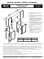
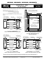
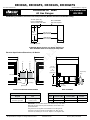
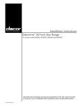
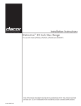
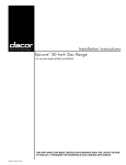
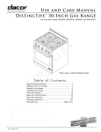
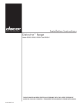
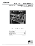
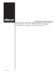
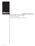
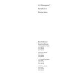
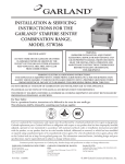
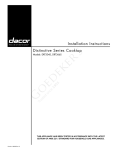
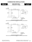
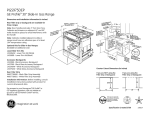
DR30GS, DR30GFS, DR30GIS, DR30GIFS
Revised 04/04/13 Page 1/5
Document # PG05-007
Distinctive™ 30” Wide
All Gas Ranges
PLANNING
GUIDE
All tolerances ±1/16” (±1.6 mm) unless otherwise noted.
warning
•
Observe all governing codes and ordinances during planning
and installation. Contact your local building department for
further information.
•
This appliance must be installed in accordance with the
accompanying installation instructions.
Front of open door
Front of handle
Front of knobs
Front panel
Rear of front panel
46 3/4” (118.7 cm)
28 9/16” (72.5 cm)
28” (71.1 cm)
26 1/8” (66.4 cm)
24” (61.0 cm)
1 1/8” (2.9 cm)
Backguard thickness
9” (22.9 cm)
Grates extend Backguard*1
1” above trim
3” (7.6 cm)
backguard*
DR30GI[F]S:
1/4” (6.4 mm)
thick top trim
External handle
shown, some models
have integral handle
(see inside cover)
DR30G[F]S:
Full stainless
steel side panels
DR30GI[F]S:
3 1/2” (8.9 cm) 2
partial stainless
steel side panels
(removable)
Product width:
29 7/8” (75.9 cm)
NOTE: Models DR30GS and
DR30GFS are not compatible
with a raised vent.
6” (15.2 cm)
backguard*
1 3/4” (4.4 cm) backguard*
1
* See table for compatibility
35”
(88.9 cm)
to
37”
(94.0 cm)
Overall Depth Dimensions - side view
Part Number
Description
Compatibility
Standard on models DR30GIS, DR30GIFS
Optional on models DR30GS, DR30GFS
AER30GLBG
Low profile (1 3/4 inch)
AERB30G03
3 Inch
Optional on models DR30GS, DR30GFS
NOT compatible with models DR30GIS, DR30GIFS
AERB30G06
6 Inch
Standard on models DR30GS, DR30GFS
NOT compatible with models DR30GIS, DR30GIFS
AERB30G09
9 Inch
Optional on models DR30GS, DR30GFS
NOT compatible with models DR30GIS, DR30GIFS
1 Only backguard model AER30GLBG is compatible with a raised vent.
Available Backguards
All specifications subject to change without notice.
www.dacor.com
Phone: (800) 793-0093
DR30GS, DR30GFS, DR30GIS, DR30GIFS
Revised 04/04/13 Page 2/5
Document # PG05-007
Distinctive 30” Wide
All Gas Ranges
PLANNING
GUIDE
All tolerances +1/16” (+1.6 mm), -0 unless otherwise noted.
B
13” (33.0 cm)
max.4
■■
Failure to meet or exceed the maximum and
minimum dimensions/clearances stated may result
in a fire hazard.
■■
The range should be placed away from drafts that
may be caused by doors, windows and heating and
air conditioning outlets.
■■
To eliminate the risk of burns or fire by reaching
over heated surface units, cabinet storage space
located above surface units should be avoided. If
cabinet storage space is to be provided directly
above the range, the risk of personal injury may be
reduced by installing a range hood.
■■
In all instances, installation of a range hood is highly
recommended. The hood should project horizontally
a minimum of five (5) inches beyond the face of
the cabinets. See the range hood specifications for
minimum clearances.
■■
If installing a raised vent, install only Dacor model
ERV3015.
■■
The range may be installed flush to the rear wall.
See diagram and notes for rear wall surface
requirements. It is not necessary to install noncombustible materials behind the range below the
countertop height.
■■
Any openings in the wall behind the appliance or in
the floor underneath it must be sealed.
Back wall
immediately
behind range6
Top of
finished
counter
Note 1
Note 5
Suggested
location of
utilities3
A
14” (35.6 cm)
min.4
Note 2
C
A*
B
C
30” min.
(76.2 cm)
36” (91.4 cm) recommended
30” (76.2 cm) min.
37” (94.0 cm)
max.
* See the cutout dimensions on following page for self-rimming installations.
Freestanding Installation Cabinet Cutout Dimensions - Models DR30GS, DR30GFS, DR30GIS and DR30GIFS
1
30” (76.2 cm) min. vertical clearance from top of range grates to bottom of uncovered wood or metal cabinet. 24” (61 cm) min. clearance if bottom of
wood or metal cabinets are protected by not less than 1/4“ (0.6 cm) flame retardant millboard covered with no less than No. 28 MSG sheet steel 0.015”
(0.04 cm) stainless steel, or 0.024” (0.06 cm) aluminum or 0.020” (0.05cm) copper. 30” (76.2 cm) min. clearance between top of range grates and bottom
of unprotected wood or metal cabinet. If installing range hood, check the hood specifications for minimum required clearances.
2
Cabinet/countertop depth is at discretion of customer but cabinet face SHALL NOT protrude further than rear of front panel. See Product Dimensions.
3
Consult local code and following pages for requirements.
4
This specification not applicable for cabinets more than a horizontal distance of 10” (25.4 cm) from edge of range.
5
10” (25.4 cm) min. to combustible sidewalls above range (both sides).
6
Non-combustible surface required for models DR30GIS and DR30GIFS up to vertical distance specified in note 1 or range hood, whichever is lower. Noncombustible surface recommended, but not required, for models DR30GS and DR30GFS.
All specifications subject to change without notice.
www.dacor.com
Phone: (800) 793-0093
DR30GS, DR30GFS, DR30GIS, DR30GIFS
Revised 04/04/13 Page 3/5
Document # PG05-007
Distinctive 30” Wide
All Gas Ranges
PLANNING
GUIDE
Self-Rimming Installation, custom Cutout Options (Models DR30GIS and DR30GIFS Only)
NOTE: The diagrams below are for installations that require custom cutouts. See page 5/5 for installation in standard 30 inch wide cutout.
All tolerances +1/16” (+1.6 mm), -0 unless otherwise noted.
10” min. (25.4 cm)
to any combustibles
above counter both sides
25 5/8”
max.
(65.1 cm)
For all self-rimming installations:
Countertop height: 34 3/4” (88.3 cm) min.
36 7/8” (93.7 cm) max.
Countertop thickness: 1 5/8” (4.1 cm) max.
1
10” min. (25.4 cm)
Rear wall or
3/4” min. (1.9 cm)
to any combustibles
countertop edge countertop overhang
above counter both sides
Non-combustible
rear wall required 1
29 1/4” (74.3 cm)
countertop opening
30” (76.2 cm)
cabinet opening
below countertop 3
Notch countertop
to width of cabinets
Cabinet face
below countertop
21”
20 3/4” (53.3 cm)�
to
(52.7 cm)
24”
(61.0 cm)
25 3/4”
(65.4 cm)
max.
Notch countertop
to width of cabinets
Cabinet face
Countertop front below countertop
2
Cabinet Depth Greater Than 24”
3 1/4” Side Panels Installed, Range Back
Overhanging Countertop (Top View)
Cabinets Less Than 24” Deep, 3 1/4” Side Panels
Installed, Range Back Flush to Wall (Top View)
10” min. (25.4 cm)
to any combustibles
above counter both sides
29 1/4” (74.3 cm)
countertop opening
30” (76.2 cm)
cabinet opening
below countertop 3
Cabinet face
below countertop
Notch countertop
overhang to width of
cabinets
29 1/4” (74.3 cm)
countertop opening
30” (76.2 cm)
cabinet opening
below countertop 3
21 1/8”
20 7/8” (53.7 cm)
to
(53.0 cm)
24 1/8”
(61.3 cm)
1
10” min. (25.4 cm)
Rear wall or
to any combustibles
countertop edge
above counter both sides
Non-combustible
rear wall required 1
24”
(61.0 cm)
Countertop overhang
1 5/8” (4.1 cm) max.
Cabinet Exactly 24” Deep, 3 1/4” Side Panels
Removed, Range Back Flush to Wall (Top View)
29 1/4” (74.3 cm)
countertop opening
30” (76.2 cm)
cabinet opening
below countertop 3
Cabinet face
below countertop
Notch countertop
overhang to width of
cabinets
1” min. (2.5 cm)
Countertop overhang
24 1/8”
(61.3 cm)
Countertop overhang
1 5/8” (4.1 cm) max.
2
Cabinet Depth Greater Than 25 1/8”
3 1/4” Side Panels Removed, Range Back
Overhanging Countertop (Top View)
1 On models DR30GIS and DR30GIS, non-combustible surface required immediately behind range, as specified on previous page, when back of
backguard is less than 2 1/2” (6.4 cm) from rear wall.
2 Models DR30GIS and DR30GIS include self-rimming trim piece that attaches to back of range and covers the edge of the countertop overhang in back.
3 To create a “built-in look” on the front of the cabinet, this dimension may be changed to 29 1/4” (74.3 cm). This configuration is only for models DR30GIS
and DR30GIS with side panels behind door removed.
All specifications subject to change without notice.
www.dacor.com
Phone: (800) 793-0093
DR30GS, DR30GFS, DR30GIS, DR30GIFS
Revised 04/04/13 Page 4/5
Document # PG05-007
Distinctive 30” Wide
All Gas Ranges
PLANNING
GUIDE
Raised Vent (Self-Rimming) Installation Cutout Options (Models DR30GIS and DR30GIFS Only)
All tolerances +1/16” (+1.6 mm), -0 unless otherwise noted.
3/8” min. (1.0 cm) flat countertop
overhang required behind cutout
For all installations with a raised vent:
Countertop height: 34 3/4” (88.3 cm) min.
36 7/8” (93.7 cm) max.
Countertop thickness: 1 5/8” (4.1 cm) max.
Wall
NOTE: For all raised vent installations, use only Dacor raised vent model
ERV3015.
10” min. (25.4 cm)
Rear wall or
to any combustibles
countertop edge
above counter both sides
3/8” (9.5 mm) min.
countertop overhang
Stiffener
Countertop
ERV3015
raised vent
27 1/2” (69.9 cm)
raised vent opening
1
29 1/4” (74.3 cm)
countertop opening
30” (76.2 cm)
cabinet opening
below countertop
Cabinet face
below countertop
Notch countertop
overhang to width of
cabinets
3”
(7.6 cm)
3/8” (9.5 mm) min.
countertop overhang
25 3/4”
(65.4 cm)
max.
30” (76.2 cm)
cabinet opening
below countertop
Cabinet face
Countertop overhang
1 5/8” (4.1 cm) max.
IMPORTANT: If optional side panels are not installed cabinet
face must be flush with back of control panel.
Side View - DR30GI[F]S Range and
ERV3015 Raised Vent
Rear wall or
countertop edge
3” (7.6 cm)
10” min. (25.4 cm)
Rear wall or
to any combustibles
countertop edge
above counter both sides
3/8” (9.5 mm) min.
countertop overhang
27 1/2” (69.9 cm)
raised vent opening
20 7/8”
20 5/8” (53.0 cm)
to
(52.4 cm)
24 1/8”
(61.3 cm)
Notch countertop
overhang to width of
cabinets
Countertop
front
Back of
control panel
3/8” min. (1.0 cm)
space behind raised vent
chassis to clear stiffener
27 1/2” (69.9 cm)
raised vent opening
1
29 1/4” (74.3 cm)
countertop opening
DR30GI[F]S
range
Shown with partial
side panel installed
20 5/8”
(52.4 cm)
24” - 24 1/4” Cabinet Depth
Partial Side Panels Installed (Top View)2
10” min. (25.4 cm)
to any combustibles
above counter both sides
29 1/2” (74.9 cm)
Cabinet face
below countertop
24 1/4” - 27 1/2” Cabinet Depth
Partial Side Panels Installed (Top View)
1
29 1/4” (74.3 cm)
countertop opening
30” (76.2 cm)
cabinet opening
below countertop
Cabinet face
below countertop
Notch countertop
overhang to width of
cabinets
3”
(7.6 cm)
24 1/8”
(61.3 cm)
Countertop overhang
1 5/8” (4.1 cm) max.
Custom Cabinet 27 1/2” or Deeper,
Partial Side Panels Removed (Top View)
1 To create a “built-in look” on the front of the cabinet, this dimension may be changed to 29 1/4” (74.3 cm). Width notches remains 30”.
2 For 24 to 24 1/4 inch deep cabinets, the side panels and control panel will protrude from the cabinet face a total of 5 5/8 inches.
All specifications subject to change without notice.
www.dacor.com
Phone: (800) 793-0093
DR30GS, DR30GFS, DR30GIS, DR30GIFS
Revised 04/04/13 Page 5/5
Document # PG05-007
PLANNING
GUIDE
Distinctive 30” Wide
All Gas Ranges
Self-Rimming Installation, Standard Cutout Requirements (Models DR30GIS and DR30GIFS Only)
10” min. (25.4 cm)
to any combustibles
above counter both sides
24 3/8”
min.
(61.9 cm)
Non-combustible
rear wall required
30” (76.2 cm)
countertop/cabinet opening
Cabinet face
below countertop
Countertop front
standard width CUTOUT FOR model dr30dI[F]S
self-rimming TRIM KIT atkdr30Gw required
10” (25.4 cm)
10” (25.4 cm)
Electrical Specifications/Dimensions, All Models
12 1/4”
(31.1 cm)
to
14 1/4”
(36.2 cm)
6’ (183 cm)
long
12” (30.5 cm)
2 1/2”
(6.4 cm)
3 1/2”
(8.9 cm)
1” (2.5 cm)
4 1/4”
(10.8 cm)
utility clearance behind range
back of range
ELECTRICAL REQUIREMENTS
GAS SUPPLY PRESSURE REQUIREMENTS
Electrical Circuit
Required
Total Connected
Load
Gas
Type
120 Vac, 60 Hz, 15 Amps.,
dedicated, grounded
4.0 Amps. @
120 Vac, 60 Hz
Natural
LP
Manifold
Pressure* (WC)
Min. Gas Supply
Pressure (WC)
Max. Input
Pressure
5”
6”
1/2 psi
10”
11”
1/2 psi
IMPORTANT: The information above is for reference only. If the above
data does not agree with the product data label, use the data on the
product data label.
The gas inlet on the regulator accommodates a 1/2” NPT gas line
connection. The range can also accommodate a 3/4” NPT gas line
connection by removing the 1/2” to 3/4” adapter on the regulator inlet.
All specifications subject to change without notice.
www.dacor.com
Phone: (800) 793-0093