1
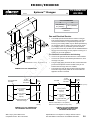
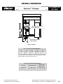
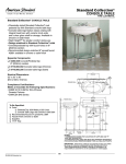
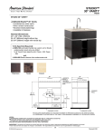
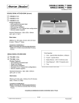
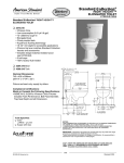
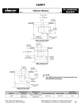
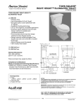
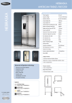
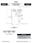
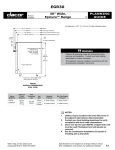
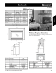
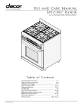
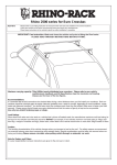
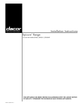
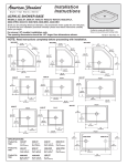
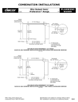
ER30D/ER30DSR
103107
Epicure™ Ranges
1/3
PLANNING
GUIDE
46 1/4” (1175mm)
28 13/16” (732mm)
27 5/16” (694mm)
26 3/8” (670mm)
24 1/4” (616mm)
All tolerances: +1/16”, -0 (+1.6mm, -0)
1 1/16” (27mm)
9” (229mm)
Backguard**
6” (152mm)
3” (76mm) Backguard**
Backguard*
* Standard
** Optional
Finished Side
Panel
37 7/8”
(962mm)
to
35 3/4”
(908mm)
45 9/16” (1157mm)
28 1/8” (714mm)
26 5/8” (676mm)
25 5/8” (651mm)
23 9/16” (598mm)
23” (584mm)
Rear of Front Panel
to Back of Chassis
Model ER30D
37 7/8”
(962mm)
to
35 3/4”
(908mm)
46 1/16” (1170mm)
28 5/8” (727mm)
27 1/8” (689mm)
26 1/8” (663mm)
24 1/16” (611mm)
23” (584mm)
Model ER30D
side dimensions
with standard trim
Rear of Front Panel
to Back of Chassis
ELECTRIC CIRCUIT REQUIREMENTS
37 7/8”
(962mm)
to
35 3/4”
(908mm)
Range Model
Circuit Required
Total Connected
Load
ER30D/ER30DSR
240VAC,
60Hz, 30A
5.6kW (23A)
The ratings above are for reference only refer to the range rating label
Model ER30
side dimensions
self rimming with erv
Web: http://www.Dacor.com
Corporate Phone: 800-793-0093
Specifications are subject to change without notice.
See installation instructions for additional details.
5.7
ER30D/ER30DSR
103107
Epicure™ Ranges
2/3
PLANNING
GUIDE
CUT-OUT DIMENSIONS
F
“F”
“G”
36” (914mm)*
30” (762mm)**
30 1/16” (916mm)*
* Recommended
** Minimum
Gas and Electrical Service
◊
The shaded area shown denotes the location of the gas
inlet and the electrical junction box/receptacle. This is the
recommended location. For replacement purposes, the
location of the existing utilities may be utilized provided they
do not interfere with the sides or rear of the range. Check
local building codes for permissible gas valve locations.
◊
An external manual shut-off valve must be installed between
the gas inlet and the range, for the purpose of turning on or
shutting off gas to the appliance.
G
24” Typ.
(610mm)
25” Typ.
(635mm)
The installation must allow for the following:
All tolerances: +1/16”, -0 (+1.6mm, -0)
Cabinet cut-out dimensions
Non-Combustible
Rear Wall
10” Min.
(254mm)
Both Sides
7/16”
(11mm)
◊
Access to the gas shut-off valve when the unit is installed.
◊
Access to the remote circuit breaker panel/fuse box, when
the range is in place.
◊
The gas supply piping and shut-off valve, and the electrical
junction box/receptacle must be located so they do not
interfere with the range when it is installed.
◊
The junction box and gas shut off valve must be located
so that the range can be pulled out for service while the
appliance remains connected.
Rear Wall
10” Min.
(254mm)
Both Sides
1/4” Min.
(6mm)
2 13/16” (71mm)
27 7/8” (708mm)
ERV Opening
29 1/4” (743mm)
Countertop
Opening
30 1/16” (764mm)
Cabinet
Opening
23 9/16”
(598mm)
24 1/16”
(611mm)
30 1/16” (764mm)
Cabinet
Opening
Combustible Side
Wall Above Range
Combustible Side
Wall Above Range
1”
(25mm)
Cabinet cut-out dimensions
self rimming installation
Web: http://www.Dacor.com
Corporate Phone: 800-793-0093
29 1/4” (743mm)
Countertop
Opening
Minimum Cabinet depth: 27 1/8” (688mm)
Minumum Countertop depth: 28 1/8” (714mm)
1”
(25mm)
Cabinet cut-out dimensions
self rimming installation
with erv raised vent
Specifications are subject to change without notice.
See installation instructions for additional details.
5.8
ER30D/ER30DSR
Epicure™ Ranges
082007
Gas Inlet
3/3
PLANNING
GUIDE
Range Electrical Access,
Cover Removed
B
D
A
E
C
Electrical Connection
Hole in Bottom
back of range
GAS - ELECTRICAL ACCESS DIMENSIONS
“A”
“B”
“D”
“C”
“E”
4 7/8”
21 3/4”
8 5/8”
10 3/16”
7/8”*
(124mm)
(552mm)
(219mm)
(259mm)
(22mm)
* The hole size can be increased to 1 1/8” by removing the conduit
bracket inside the range electrical access box.
GAS SUPPLY PRESSURE REQUIREMENTS
Web: http://www.Dacor.com
Corporate Phone: 800-793-0093
Gas Type
Manifold Pressure
Minimum Gas
Supply Pressure
Natural Gas
5” Water Column
6” Water Column
Petroleum (LP)
10” Water Column
11” Water Column
Specifications are subject to change without notice.
See installation instructions for additional details.
5.9