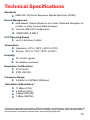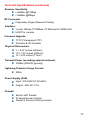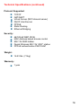
1
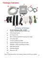
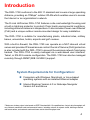
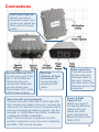
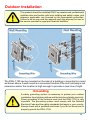
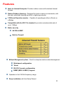
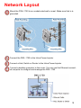
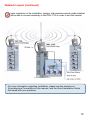
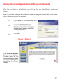
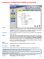
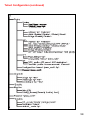
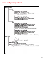
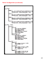
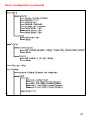
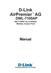
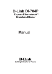
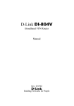
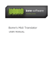
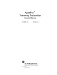
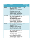
D-Link AirPremier DWL-1750 Outdoor 2.4 GHz Wireless Router/Bridge Manual This product should be installed ONLY by experienced, professional installers who are familiar with local building and safety codes, and wherever applicable, are licensed by the appropriate authorities. Failure to do so may void the warranty and may expose the user or the service provider to legal and financial liabilities. Building Networks for People Contents Package Contents ................................................................................ 3 Introduction ........................................................................................... 4 Connections ......................................................................................... 5 Outdoor Installation .............................................................................. 6 Grounding ............................................................................................. 6 Antenna ................................................................................................ 7 Features ............................................................................................... 8 Network Layout .................................................................................... 9 Using the Configuration Utility .............................................................11 Networking Basics .............................................................................. 33 Frequently Asked Questions .............................................................. 48 Troubleshooting .................................................................................. 50 Appendix I: Telnet Configuration (optional)......................................... 55 Appendix 2: Boot Code Firmware Upgrade ........................................ 64 Technical Specifications ..................................................................... 76 Contacting Technical Support ............................................................. 79 Warranty and Registration .................................................................. 80 2 Package Contents 1 7 8 4 6 5 10 2 9 3 Contents of Package: 1 D-Link AirPremier DWL-1700AP Outdoor 2.4GHz Wireless Access Point 2 Inline Power Injector 3 AC Power Cord 4 5 6 7 MIL-C-5015 style RS232 Console Port Cable Grounding Wire Crossover Ethernet Cable Reverse Polarity-N Female RF Cable 30M MIL-C-5015 style Ethernet Cable 8 Mast Mounting Kit 9 Wall Mounting Kit 10 Manual on CD 11 If any of the above items are missing, please contact your reseller. 3 Introduction The DWL-1750 conforms to the 802.11 standard and covers a large operating distance, providing an 11Mbps* outdoor WLAN which enables users to access the Internet or an organization’s network. The D-Link AirPremier DWL-1750 features a die-cast watertight housing and a built-in lightning protector to protect it from harsh environmental conditions, including extreme variance in temperature. It also includes Power over Ethernet (PoE) and a unique outdoor remote-mounted design for easy installation. The DWL-1750 is suitable for manufacturing plants, industrial sites, military bases, universities, hotels, airports and golf courses. With a built-in firewall, the DWL-1750 can operate as a NAT inbound virtual server and provides IP based access control. Denial of Service (DoS) protection is also included with the DWL-1750 to prevent the wireless network from being hacked. The DWL-1750 is easily managed via a web-based user interface, Telnet, or RS-232 console configuration. The DWL-1750 can also be managed remotely through SNMP (MIB I & MIB II) support. System Requirements for Configuration: Computers with Windows, Macintosh, or Linux-based operating systems with an installed Ethernet adapter Internet Explorer Version 6.0 or Netscape Navigator Version 6.0 and Above *”Maximum wireless signal rate based on IEEE Standard 802.11b specifications. Actual data throughput will vary. Network conditions and environmental factors, including volume of network traffic, building materials and construction, and network overhead lower actual data throughput rate.” 4 Connections PoE Power Injector Attach one end of the power cord to the power port; attach the other end to the wall outlet. Special Ethernet Port Connect one end of the MIL-C-5015 Ethernet Cable into this port; connect the other end into the Power and Data Output Port on the Inline Power Injector. Reverse Polarity -N Type Connector for connecting the antenna or RF cable. Special serial port (optional) Connect one end of the MIL-C-5015 style RS232 console port cable to this port; connect the other end to a Serial Port on a computer that is running a terminal emulation program. Set the terminal to 15200 Baud, No Parity, 8 data bits, 1 stopbit and ANSI compatible. Note: This connection is optional. Use this console connection only if you are configuring the DWL-1750 via the console. Data Input Port Connect one end of the cross-over Ethernet cable to this port; connect the other end to the Ethernet port on the computer. Power & Data Output Port Attach one end of the special Ethernet cable to this port; attach the other end to the Special Ethernet Port on the DWL-1750. 5 Outdoor Installation This product should be installed ONLY by experienced, professional installers who are familiar with local building and safety codes, and wherever applicable, are licensed by the appropriate authorities. Failure to do so may void the warranty and may expose the user or the service provider to legal and financial liabilities. The DWL-1750 can be mounted on the side of a building or mounted to a mast as shown above. A wall mount is a convenient location if the roof overhang is not excessive and/or the location is high enough to provide a clear line of sight. Grounding A safety grounding system is necessary to protect your outdoor installation from lightning strikes and the build-up of static electricity. Direct grounding of the antenna mast and the DWL-1750 is very important. The grounding system must comply with the National Electrical Code and the safety standards that apply in your country. Always check with a qualified electrician if you do not know how to properly ground the DWL-1750. 6 Antenna Mast Requirements To accommodate the outdoor antennas, the antenna mast must satisfy the following requirements: The construction of the mast must be of a sturdy, weatherproof and no corrosive material like examples of galvanized or stainless steel construction pipe. Typical diameter of the mast should be between 35 mm (1.4 in.) and 41 mm (1.625 in.). Subjecting to the type of antenna that you intend to install other diameters may be possible as well. The height of the antenna mast must be sufficient to allow the antenna to be installed at least 1.5 m (5 ft.) above the peak of roof. If the roof is metal, then the height of the antenna should be a minimum of 3 m (10 ft) above the roof. The mast or wall-bracket must be free from any substance that may avoid a good electrical connection with the antenna; for example, paint. Antenna Alignment For optimal performance of your wireless link, make sure that the antennas are properly aligned (facing one another “eye-to-eye”). To align the antennas: Use a pair of binoculars and/or a map of the area and compass to point the antennas to one another. Use the Utility - “Wireless Link Info” in the Web Configure as described in the “Utility” section to analyze the radio link quality. The “Wireless Link Info” will enable you to display the levels of signal strength and link quality. Looking at the Wireless Link Info screen, you can interactively optimize antenna alignment if required, by making small modifications in the antenna orientation. Alternatively, consult a professional Antenna Installation Service to optimize the antenna alignment. Omni-directional antennas are characterized by a wide radiation pattern. Therefore alignment of this type of antennas is less critical than for directional antennas. 7 Features Ideal for Internet Hotspots- Provides outdoor users with wireless Internet Access Robust Outdoor Housing - Designed for harsh outdoor environments, with die-cast, watertight housing and built-in lightning protector 2 Different Operation modes - Capable of operatingas either a Router or a Bridge. Compatible with the 802.11b standard to provide a wireless data rate of up to 11Mbps. Better security 64/128 bit WEP Built-in Firewall Multiple Management options - Great for enterprise wireless networkmanagement Web-based configuration Telnet RS-232 Console configuration SNMP (MIB I & MIB II) support Operates in the 2.4GHz frequency range Easy Installation with the Setup Wizard 8 Network Layout Mount the DWL-1750 to an unobstructed wall or mast. Make sure that is is grounded. Connect the DWL-1750 to the Inline Power Injector Connect a Hub, Switch or Router to the Inline Power Injector Connect a desktop computer to the router. You can use this Ethernet connected computer to configure and manage the DWL-1750 9 Network Layout (continued) Upon completion of the installation, laptops, with wireless network cards installed, will be able to connect wirelessly to the DWL-1750 in order to surf the Internet. For more information regarding installation, please see the sections on Grounding and Connections in this manual, and the Quick Installation Guide that came with your purchase. 10 Using the Configuration Utility To configure the DWL-1750, use a computer which is connected to the DWL-1750 with an Ethernet cable (see the Network Layout diagram). First, disable the Access the Internet using a proxy server function. To disable this function, go to Control Panel > Internet Options > Connections > LAN Settings and uncheck the enable box. Start your Microsoft Internet Explorer web browser program. Type the IP Address and HTTP port of the DWL-1750 (the default port is 2000; the IP is 192.168.0.50) in the address field (http://192.168.0 .50:2000/) and press Enter. Make sure that the IP Addresses of the DWL-1750 and your computer are in the same subnet. 11 Using the Configuration Utility (continued) After the connection is established, you will see the user identification window as shown. Note: if you have changed the default IP Address assigned to the DWL-1750, make sure to enter the correct IP Address. Type admin in the User Name field Leave the Password blank. (However, if you have changed the password, please enter the correct password.) Click OK Connect to 192.168.0.1 Home > Wizard The Home>Wizard screen will appear. Please refer to the Quick Installation Guide for more information regarding the Setup Wizard. 12 Using the Configuration Utility (continued) Home > Wireless SSID- Service Set Identifier (SSID) is the name designated for a specific wireless local area network (WLAN). The SSID’s factory default setting is default. The SSID can be easily changed to connect to an existing wireless network or to establish a new wireless network. Channel- 6 is the default channel. All devices on the network must share the same channel. WEP- Wired Equivalent Privacy (WEP) is a wireless security protocol for Wireless Local Area Networks (WLAN). WEP provides security by encrypting the data that is sent over the WLAN. Select Enabled or Disabled. Disabled is the default setting. (Note: If you enable encryption on the DWL-1750 make sure to also enable encryption on all the wireless clients or wireless connection will not be established). WEP Encryption- Select the level of encryption desired: 64-bit, or 128-bit Key Type- Select HEX or ASCII Passphrase- Select HEX in the Key Type field and enter the passphrase here Hexadecimal digits consist of the numbers 0-9 and the letters A-F ASCII (American Standard Code for Information Interchange) is a code for representing English letters as numbers from 0-127 Keys 1-4Apply- Input up to 4 WEP keys; select the one you wish to use Click Apply to save the changes 13 Using the Configuration Utility (continued) Home > Mode > Central Dynamic IP Router Select Central Dynamic IP Router if you are locating the router in a central position to obtain an IP Address automatically from your ISP or corresponding wireless network. Most Cable Modem Users will select this option. WAN - Ethernet Host Name- You may enter the Host Name here (optional) NAPT- Select Disable or Enable. NAPT is a form of NAT; it provides a type of firewall by hiding internal IP Addresses and it works as an inbound virtual server, with IP based access control LAN - Wireless IP Address- Enter the wireless IP Address of the DWL-1750. The default IP Address is 192.168.1.50 Subnet Mask- Enter the subnet mask. All devices on your network should have the same subnet mask Apply- Click Apply if you have made any changes 14 Using the Configuration Utility (continued) Home > Mode > Central Static IP Router Select Central Static IP Router mode if the DWL-1750 will be in a central location. In this mode you will enter the Static IP Address that is provided to you by your ISP. WAN - Ethernet IP AddressEnter the IP Address assigned by your ISP Subnet MaskAll devices in the network must have the same Subnet Mask ISP Gateway AddressYour ISP will provide this information DNS Server AddressNAPTLAN - Wireless Your ISP will provide this information Select Disable or Enable. NAPT is a form of NAT; it provides a type of firewall by hiding internal IP Addresses and it works as an inbound virtual server, with IP based access control IP Address- Enter the IP Address assigned by your ISP Subnet Mask- All devices in the network must have the same Subnet Mask Apply- Click Apply if you have made any changes 15 Using the Configuration Utility (continued) Home > Mode > Central PPPoE Router > Dynamic or Static PPPoE Select Central PPPoE Router mode if your ISP uses PPPoE. Most DSL users will select this option. WAN - PPPoE Dynamic or Select the appropriate PPPoE used by your ISP Static PPPoEThe default User Name is user User NamePasswordEnter a password Retype Re-enter the password PasswordService NameThis field is optional IP AddressFor Static PPPoE, enter an IP Address, provided by your ISP Maximum Idle TimeNAPT- Select the maximum idle time Select Disable or Enable. NAPT is a form of NAT; it provides a type of firewall by hiding internal IP Addresses and it works as an inbound virtual server, with IP based access control LAN - Wireless IP Address- Enter the IP Address assigned by your ISP Subnet Mask- All devices in the network must have the same Subnet Mask Click Apply- Click Apply if you have made any changes 16 Using the Configuration Utility (continued) Home > Mode > Remote Static IP Router Select this option to input the Remote Static IP Address provided by your ISP WAN - Wireless IP Address- Input the IP Address assigned by your ISP Subnet Mask- Input the Subnet Mask; all devices in the network must use the same Subnet Mask ISP Gateway Your ISP will provide this information AddressDNS Server AddressNAPTLAN - Ethernet IP Address- Your ISP will provide this information Select Disable or Enable. NAPT is a form of NAT; it provides a type of firewall by hiding internal IP Addresses and it works as an inbound virtual server, with IP based access control The default IP Address of the Ethernet port is 192.168.0.50 Subnet Mask- All devices in the network must have the same Subnet Mask Click Apply- Click Apply if you have made any changes 17 Using the Configuration Utility (continued) Home > Mode > Remote Bridge Bridge IP IP Address- Input the IP Address assigned by your ISP Subnet Mask- Input the Subnet Mask; all devices in the network must use the same Subnet Mask ISP Gateway Address- Your ISP will provide this information DNS Server Address- Your ISP will provide this information Apply- Click Apply if you have made any changes 18 Using the Configuration Utility (continued) Home > Mode > Central Bridge Bridge IP IP Address- Input the IP Address assigned by your ISP Subnet Mask- Input the Subnet Mask; all devices in the network must use the same Subnet Mask ISP Gateway Address- Your ISP will provide this information DNS Server Address- Your ISP will provide this information Apply- Click Apply if you have made any changes 19 Using the Configuration Utility (continued) Home > DHCP DHCP stands for Dynamic Host Control Protocol. The DWL-1750 has a built-in DHCP server. The DHCP Server will automatically assign an IP Address to the computers on the LAN/private network. Be sure to set your computers to be DHCP clients by setting their TCP/IP settings to “Obtain an IP Address Automatically.” When you turn your computers ON, they will automatically load the proper TCP/IP settings provided by the DWL-1750. The DHCP Server will automatically allocate an unused IP Address from the IP Address pool to the requesting computer. You must specify the starting and ending address of the IP Address pool. Trigger DHCP ServiceDefault way- Gate- Select Enable to use the DHCP feature of the DWL-1750. Select Disable to disable this function Enter the wireless IP Address of the DWL-1750 Net Mask- The subnet mask of the LAN interface The default subnet mask is 255.255.255.0 DHCP Start IP- The starting IP Address for the DHCP server’s IP Assignment DHCP End IP- The ending IP Address for the DHCP server’s IP Assignment Lease Time- The length of time for the DHCP lease Interface- Select Wireless or Ethernet DHCP Client Table- Lists the DHCP clients connected to the DWL-1750. Click Refresh to update the list. The talbe will show the Host Name, IP Address, and MAC Address of the DHCP client computer. Click Apply to save the changes. 20 Apply- Using the Configuration Utility (continued) Advanced > Virtual Server The DWL-1750 can be configured as a Virtual Server so that remote users accessing Web and FTP services via the public IP Address can be automatically redirected to local servers in the LAN (Local Area Network.) The DWL-1750 firewall feature filters out unrecognized packets to protect your LAN network so all computers networked with the DWL-1750 are invisible to the outside world. If you wish you can make some of the LAN computers accessible from the Internet by enabling Virtual Server. Each Virtual Service that is created will be listed at the bottom of the screen in the Virtual Servers List Name- The Name referencing the virtual service Private IP- The server computer in the LAN that will be providing virtual services Protocol Type- The protocol used for the virtual service Private Port- The port number of the service used by the Private IP computer Public Port- The port number on the WAN side that will be used to access the virtual service Schedule- Choose whether the service will be ON or OFF Apply- Click Apply if you have made any changes 21 Using the Configuration Utility (continued) Advanced > Filters Filters are used to deny or allow LAN computers from accessing the Internet using their MAC Addresses Disable or Enable Click Enable to enable the MAC filter. By enabling the filter you allow access to the Internet to only those computers whose MAC Addresses are listed in the filter list. Computers not listed are blocked from the Internet. MAC Address - Enter the MAC Address of the wireless LAN user that will be allowed Internet access when the filter is enabled. Apply- Click Apply if you have made any changes MAC Address - Media Access Control Address A unique hardware address that identifies a device on a network. It is assigned at the factory and cannot be changed. Usually you will find this address on a sticker on the device or packaging. 22 Using the Configuration Utility (continued) Advanced > Firewall Firewall Rules is an advanced feature that is used to deny or allow traffic that passes through the DWL-1750. The Firewall Rules that you create will appear in the list at the bottom of the page. Please be sure to Click Apply, after you have made changes or additions. Firewall Service- Select Enabled to enable the Firewall Service feature Rule Name- Enter the name for the Firewall Rule Schedule- To schedule select OFF or ON Action- Choose to Accept or Deny the Firewall Rule Priority- Select the Priority status of the Firewall Rule Protocol- Select the Protocol of the Firewall Rule IP- Enter the IP Address of both the Source and the Destination of the Firewall Rule Netmask- Enter the Subnet Mask of both the Source and the Destination of the Firewall Rule Port- Enter the Port of both the Source and the Destination of the Firewall Rule Apply- Click Apply if you have made any changes 23 Using the Configuration Utility (continued) Advanced > Performance Beacon Interval- Beacons are packets sent by an Access Point to synchronize a wireless network. Specify a value. 100 is the default setting and is recommended. RTS Threshold- This value should remain at its default setting of 250. If you encounter inconsistent data flow, only minor modifications should be made within the value range of 0-3000. Fragmentation- The fragmentation threshold, which is specified in bytes, determines whether packets will be fragmented. Packets exceeding the 1600 byte setting will be fragmented before transmission. 1600 is the default setting. SSID Broadcast- Enable the SSID Broadcast feature to announce the SSID across the network. Enabling this will allow you to use XP’s site survey tools. Disabling SSID Broadcast can be a useful security measure. Apply- Click Apply if you have made any changes. 24 Using the Configuration Utility (continued) Advanced > Routing Network Address - Enter the Network IP Address Subnet Mask - Enter the Subnet Mask Gateway Address - Enter the Gateway Address Static Route List - Displays a list of the Static Routes that you have entered Apply - Click Apply if you have made any changes 25 Using the Configuration Utility (continued) Advanced > SNMP SNMP (Simple Network Management Protocol) is a widely used network monitoring and control protocol that reports activity on each network device to the administrator of the network. SNMP can be used to monitor traffic and statistics of the DWL-1750. 26 Using the Configuration Utility (continued) Advanced > Anti-DoS Select one or more of these options to reject DoS (Denial of Service) attacks. Some CPU resources are used in Anti-DoS attacks. If you notice performance degradation, you may wish to adjust the selection of Anti-DoS attacks. 27 Using the Configuration Utility (continued) Tools> Admin At this page, the DWL-1750 administrator can change the system password. The Login name is admin. New Password- Enter a new password in this field Confirm Password- Retype the password for confirmation Block WAN Ping Disable Ping from the WAN side- Disabling Ping from the WAN side will eliminate one method that hackers can use to intrude on your network Remote Management Disable Remote Manager from WAN SideHTTP Port- Check here to disable Remote Manager from the WAN side Enter the HTTP Port Apply- Click Apply to save changes 28 Using the Configuration Utility (continued) Tools > System The current system settings can be saved as a file onto the local hard drive. The saved file or any other saved setting file can be loaded back on the DWL-1750. To reload a system settings file, click on Browse to browse the local hard drive and locate the system file to be used. You may also reset the DWL-1750 back to factory settings by clicking on Default. Save Settings to Local Hard Drive- Click Backup to save the current settings to the local Hard Drive Load Settings from Local Hard Drive- Click Browse to find the settings, then click Restore Save Current Config- Click Save to save the current configuration Reset to Default- Click Default to reset to factory default settings Restart Device- Click Reboot to Restart the DWL-1750 Apply- Click Apply to save changes 29 Using the Configuration Utility (continued) Tools > Firmware There may be new firmware for your DWL-1700AP available on the D-Link support website. Click here to check for a firmware upgrade on our support site. You will need to download and install TFTP software on a computer in your network. Copy the firmware upgrade file that you downloaded from our website into the TFTP folder on your hard-drive. You can upgrade the firmware here. Make sure the firmware you want to use has been copied into the TFTP folder on the computer in your network which has the TFTP software installed. Remember the names of the firmware upgrade files. Please check the D-Link support site for firmware updates at http://support.dlink.com. You can download firmware upgrades to your hard drive from the D-Link support site. Firmware Upgrade- Click on the link in this screen to find out if there is an updated firmware; if so, download the new firmware to your hard drive and into the TFTP server folder. TFTP Server IP- Input the IP Address of the computer on the network which has the TFTP software installed. Program Firmware- Enter the name of the program firmware update file that you downloaded into the TFTP folder. Web image Firmware- Enter the name of the Web image firmware update file that you downloaded into the TFTP folder. Apply- Click Apply to update the firmware. 30 Using the Configuration Utility (continued) Status > Device Info The Device Info screen displays information about the DWL-1750. 31 Using the Configuration Utility (continued) Status > Wireless The screen above displays the Wireless Status and the length of time of the current connection. Help At the Help screen you can select from Help files displayed above. 32 Networking Basics Using the Network Setup Wizard in Windows XP In this section you will learn how to establish a network at home or work, using Microsoft Windows XP. Note: Please refer to websites such as http://www.homenethelp.com and http://www.microsoft.com/windows2000 for information about networking computers using Windows 2000, ME or 98. Go to Start>Control Panel>Network Connections Select Set up a home or small office network When this screen appears, Click Next. 33 Networking Basics (continued) Please follow all the instructions in this window: Click Next In the following window, select the best description of your computer. If your computer connects to the internet through a gateway/router, select the second option as shown. Click Next 34 Networking Basics (continued) Enter a Computer description and a Computer name (optional.) Click Next Enter a Workgroup name. All computers on your network should have the same Workgroup name. Click Next 35 Networking Basics (continued) Please wait while the Network Setup Wizard applies the changes. When the changes are complete, Click Next. Please wait while the Network Setup Wizard configures the computer. This may take a few minutes. 36 Networking Basics (continued) In the window below, select the option that fits your needs. In this example, Create a Network Setup Disk has been selected. You will run this disk on each of the computers on your network. Click Next. Insert a disk into the Floppy Disk Drive, in this case drive A. Click Next 37 Networking Basics (continued) Please read the information under Here’s how in the screen below. After you complete the Network Setup Wizard you will use the Network Setup Disk to run the Network Setup Wizard once on each of the computers on your network. Click Next. 38 Networking Basics (continued) Please read the information on this screen, then click Finish to complete the Network Setup Wizard. The new settings will take effect when you restart the computer. Click Yes to restart the computer. You have completed configuring this computer. Next, you will need to run the Network Setup Disk on all the other computers on your network. After running the Network Setup Disk on all your computers, your new wireless network will be ready to use. 39 Networking Basics (continued) Naming your Computer To name your computer, please follow these directions:(In Windows XP) Click Start (in the lower left corner of the screen) Right-click on My Computer Select Properties and Click Select the Computer Name Tab in the System Properties window. You may enter a Computer Description if you wish; this field is optional. To rename the computer and join a domain, Click Change. 40 Networking Basics (continued) Naming your Computer In this window, enter the Computer name Select Workgroup and enter the name of the Workgroup All computers on your network must have the same Workgroup name. Click OK Checking the IP Address in Windows XP The adapter-equipped computers in your network must be in the same IP Address range (see Getting Started in this manual for a definition of IP Address Range.) To check on the IP Address of the adapter, please do the following: Right-click on the Local Area Connection icon in the task bar Click on Status 41 Networking Basics (continued) Checking the IP Address in Windows XP This window will appear. Click the Support tab Click Close Assigning a Static IP Address in Windows XP/2000 Note: Residential Gateways/Broadband Routers will automatically assign IP Addresses to the computers on the network, using DHCP (Dynamic Host Configuration Protocol) technology. If you are using a DHCP-capable Gateway/Router you will not need to assign Static IP Addresses. If you are not using a DHCP capable Gateway/Router, or you need to assign a Static IP Address, please follow these instructions: Go to Start Double-click on Control Panel 42 Networking Basics (continued) Assigning a Static IP Address in Windows XP/2000 Double-click on Network Connections Right-click on Local Area Connections Double-click on Properties 43 Networking Basics (continued) Assigning a Static IP Address in Windows XP/2000 Click on Internet Protocol (TCP/IP) Click Properties Input your IP Address and subnet mask. (The IP Addresses on your network must be within the same range. For example, if one computer has an IP Address of 192.168.0.2, the other computers should have IP Addresses that are sequential, like 192.168.0.3 and 192.168.0.4. The subnet mask must be the same for all the computers on the network.) Input your DNS server addresses. (Note: If you are entering a DNS server, you must enter the IP Address of the Default Gateway.) The DNS server information will be supplied by your ISP (Internet Service Provider.) Click OK 44 Networking Basics (continued) Assigning a Static IP Address with Macintosh OSX Go to the Apple Menu and select System Preferences cClick on Network Select Built-in Ethernet in the Show pull-down menu Select Manually in the Configure pull-down menu Input the Static IP Address, the Subnet Mask and the Router IP Address in the appropriate fields Click Apply Now 45 Networking Basics (continued) Selecting a Dynamic IP Address with Macintosh OSX Go to the Apple Menu and select System Preferences Click on Network Select Built-in Ethernet in the Show pull-down menu Select Using DHCP in the Configure pull-down menu Click Apply Now The IP Address, Subnet mask, and the Router’s IP Address will appear in a few seconds 46 Networking Basics (continued) Checking the Wireless Connection by Pinging in Windows XP and 2000 Note: The following illustrations are examples only. The IP Address that you are pinging may be different from those in the following examples. Go to Start > Run > type cmd. A window similar to this one will appear. Type ping xxx.xxx.xxx.xxx, where xxx is the IP Address of the Wireless Router or Access Point. A good wireless connection will Checking thefour Wireless show replies Connection by Pinging in Windows Me and from the Wireless 98 Router or Acess Point, as shown. Go to Start > Run > type command. A window similar to this will appear. Type ping xxx.xxx. xxx.xxx where xxx is the IP Address of the Wireless Router or Access Point. A good wireless connection will show four replies from the wireless router or access point, as shown. 47 Frequently Asked Questions Q1: How do I configure Static Routing on the DWL-1750? A: The DWL-1750 supports the Static Route function; refer to the following descriptions to configure your static routing: Network Address: Do not specify the IP address; input the Network address instead Ex: 192.168.100.0, 192.168.0.0, 10.0.0.0, etc. Subnet Mask: Enter the subnet mask of the network Gateway: The next hop IP address (i.e., the next device or router on the network path to the destination). Q2: The connecting distance of the DWL-1750 Estimated Transmission Range: Estimated Range (Miles) Remote DWL-1750 (23dBm) Antenna Gain (dBi) Central DWL-1750 (23dBm) 8 12 14 18 23 8 1.99 3.11 3.91 6.21 12 3.10 4.97 14 3.91 6.21 7.89 12.49 22.25 18 6.21 9.88 12.49 19.82 35.29 23 11.12 17.65 22.25 35.29 62.95 11.12 9.88 48 Frequently Asked Questions (continued) Remarks: - Actual Clearance is > 32.8 feet (10m.) - Distances over 25 Miles (40km) are very difficult to align and install. - This range is the maximum range, the real range depends on environmental factors. - This chart is based on 2dB cable and connector loss. Q3: How can you tell if a connection between two DWL-1750s (Central/ Remote) is established or not? A: You can check the Wireless Link Information in the Status > Wireless screen in the Configuration Utility. You will find the Link Quality, Signal Strength, Current radio channel and Current Tx Rate to show you if your connection has been established. Note: This function is only supported in Remote Router/Bridge mode. Q4: How do you backup the MAC Filters or Firewall rules in DWL-1750? A: Go to the Tools>System window in the Configuration Utility. Use the backup function on that page. Q5: How can I reset the DWL-1750 to the factory default value? A: From the WEB GUI – click the Default button in Tools > System From the RS-232 console – In the console window, press the D button on the keyboard and choose the Y to reset the DWL-1750 to its factory default setting. Q6: Does the DWL-1750 support the function to change to output power manually? A: The function is not supported in the current version. 49 Troubleshooting This Chapter provides solutions to problems that can occur during the installation and operation of the DWL-1750 Wireless Bridge/Router. We cover various aspects of the network setup, including the network adapters. Please read the following if you are having problems. Note: It is recommended that you use an Ethernet connection to configure the DWL-1750 Wireless Bridge/Router. 1.The computer used to configure the DWL-1750 cannot access the Configuration menu. Check that the Ethernet Cable is being used correctly. The Crossover Ethernet cable that comes with the DWL-1750 is used only when the unit is connected to your PC directly. If the DWL-1750 is connected to a switch, a Straight-through cable must be used, not a Crossover cable. Check that the Ethernet Adapter is working properly. Please see item 3 (Check that the drivers for the network adapters are installed properly) in this Troubleshooting section to check that the drivers are loaded properly. Check that the IP Address is in the same range and subnet as the DWL-1750. Please see Checking the IP Address in Windows XP in the Networking Basics section of this manual. Note: The default Ethernet IP Address of the DWL-1750 is 192.168.0.50; the default wireless IP Address is 192.168.1.50. All the computers on the network must have a unique IP Address in the same range, e.g., 192.168.0.x. Any computers that have identical IP Addresses will not be visible on the network. They must all have the same subnet mask, e.g., 255.255.255.0 Do a Ping test to make sure that the DWL-1750 is responding. Go to Start>Run>Type Command>Type ping 192.168.0.50. A successful ping will show four replies. Note: If you have changed the default IP Address, make sure to ping the correct IP Address assigned to the DWL-1750. 50 Troubleshooting (continued) 2. The wireless client cannot access the Internet in the Infrastructure mode. Make sure the wireless client is associated and joined with the correct Access Point. To check this connection: Right-click on the Local Area Connection icon in the taskbar> select View Available Wireless Networks. The Connect to Wireless Network screen will appear. Please make sure you have selected the default Check that the IP Address assigned to the wireless adapter is within the same IP Address range as the access point and gateway. (Since the DWL-1750 has a wireless IP Address of 192.168.1.50, wireless adapters must have an IP Address in the same range, e.g., 192.168.1.x. Each device must have a unique IP Address; no two devices may have the same IP Address. The subnet mask must be the same for all the computers on the network.) To check the IP Address assigned to the wireless adapter, double-click on the Local Area Connection icon in the taskbar > select the Support tab and the IP Address will be displayed. (Please refer to Checking the IP Address in the Networking Basics section of this manual.) If it is necessary to assign a Static IP Address to the wireless adapter, please refer to the appropriate section in Networking Basics. If you are entering a DNS Server address you must also enter the Default Gateway Address. (Remember that if you have a DHCP-capable router, you will not need to assign a Static IP Address. See Networking Basics: Assigning a Static IP Address.) 51 Troubleshooting (continued) 2. The wireless client cannot access the Internet in the Check to make sure that the Router in your network is functioning properly by pinging it. If the router is not functioning properly, it will not connect to the Internet. If you need to find out how to ping network devices, please refer to “Checking the Wireless Connection by pinging” in the Networking Basics section of this manual. Check to make sure that the DNS server in your network is functioning properly by pinging it. If the DNS server is not functioning properly, you may be unable to access the Internet. Typically, your ISP (Internet Service Provider) will be able to give you the DNS server information. If you need to find out how to ping network devices, please refer to “Checking the Wireless Connection by pinging” in the Networking Basics section of this manual. 3. Check that the drivers for the network adapters are installed properly. You may be using different network adapters than those illustrated here, but this procedure will remain the same, regardless of the type of network adapters you are using. Go to Start > My Computer > Properties Select the Hardware Tab Click Device Manager 52 Troubleshooting (continued) Double-click on Network Adapters Right-click on D-Link AirPlus DWL-G650 Wireless Cardbus Adapter (In this example we use the DWL-G650; you may be using other network adapters, but the procedure will remain the same.) D-Link AirPlus DWL-G650 Select Properties to check that the drivers are installed properly D-Link AirPlus DWL-G650 Wireless Cardbus Adapter D-Link AirPlus DWL-G650 Wireless Cardbus Adapter Look under Device Status to check that the device is working properly Click OK 53 Troubleshooting (continued) 4. What variables may cause my wireless products to lose reception? D-Link products let you access your network from virtually anywhere you want. However, the positioning of the products within your environment will affect the wireless range. Please refer to Installation Considerations in the Wireless Basics section of this manual for further information about the most advantageous placement of your D-Link wireless products. 6. Why can’t I get a wireless connection? If you have enabled Encryption on the DWL-1750, you must also enable encryption on all wireless clients in order to establish a wireless connection. Make sure that the SSID on the Access Point and the Wireless Client are exactly the same. If they are not, wireless connection will not be established. Disable all security settings (WEP, MAC Address Control). Turn off your DWL-1750 and the client (the device to which it is communicating). Turn the DWL-1750 back on again, and then turn on the client. Make sure that all devices are set to Infrastructure mode. Check that the LED indicators are indicating normal activity. If not, check that the AC power and Ethernet cables are firmly connected. Check that the IP Address, subnet mask, and gateway settings are correctly entered for the network. 7. I forgot my encryption key Reset the DWL-1750 to its factory default settings and restore the other devices on your network to their default settings. You will lose the current configuration settings. Reset and restore the DWL-1750 to the factory default settings, without WEP encryption, by using Telnet or the Console connection. Please see the Appendix in this manual for information on how to use Telnet and/or the Console connection. 54 Appendix 1: Telnet Configuration The DWL-1750 is designed to operate as shipped from the factory without any special set-up. However, it has many options and parameters that can be changed if users have special requirements. Most of the management functions can be accessed using TCP/IP protocol; it can also be configured by Telnet/Console. Configure the DWL-1750 using a Telnet session on a wired LAN attached computer. To use the Telnet session, you can simply open a Telnet window using the IP address that has been assigned to the DWL-1750. 1. Go to Start >Run; open the Run dialog box. Enter telnet 192.168.0.50 (the default terminal type of Telnet is VT100; the default Ethernet IP Address of the DWL-1750 is 192.168.0.50). Click OK. telnet 192.168.0.50 55 Telnet Configuration (continued) 2. Enter the User Name and User Password as shown below. (The default User Name is user1 and the default User Password is test.) After you have logged in, the Telnet user interface screen will appear, as shown below. 56 Telnet Configuration (continued) 3. The structure of the menu tree is shown on the following page. Users can use the following keys to select the parameter to change or add. Up/Down or i/k key: move the cursor up/down to the specific item. Right or l or Enter key: select the item or enter the sub-menu. Left or j key: return to previous menu page. Home or Ctrl-A: move the cursor to the first item of the menu page. End or Ctrl-E: move the cursor to the last item of the menu page. Ctrl-Q or F1: Show the help page. Hint 1: * denotes that the function is displayed after enable configuration mode is enabled. Hint 2: In item su, type the default password root to enter the supervisor configuration mode. 57 Telnet Configuration (continued) 58 Telnet Configuration (continued) 59 Telnet Configuration (continued) 60 Telnet Configuration (continued) 61 Telnet Configuration (continued) 62 Telnet Configuration (continued) 63 Appendix 2: Boot Code Firmware Upgrade This procedure is optional. If you wish to upgrade the Boot Code, check the D-Link support website to see if the Boot Code has been upgraded. If it has, and you wish to upgrade it (optional), here is the procedure to upgrade the Boot Code, program firmware and Web image by using the console port. Command explanation: DLSC Erase the old configuration file DLX Upgrade Boot Code DLS Upgrade program image file DLP Upgrade Web image file BE CAREFUL!! If you failed in any command, please DO NOT “Power Off” or “Reboot” the machine!! You must RETRY this command until it succeeds! Procedure: 1. Connect the power supply to the Inline Power Injector and the power outlet. 2. Connect MIL-C-5015 style Ethernet cable into the Special Ethernet port of the DWL-1750. 3. Connect the RJ-45 Ethernet connector (another end of MIL-C-5015 style Ethernet cable) into the Power & Data Output Port of the Inline Power Injector. 4. Connect the MIL-C-5015 style RS232 Console Port cable into the PC COM port and the DWL-1750 special serial port. Use HyperTerminal to upgrade the software: Click Start and then select Programs > Accessories > Communications > HyperTerminal. 64 Boot Code Firmware Upgrade (continued) After the Hyper Terminal window appears: Give this new connection a name. (e.g., DWL-1750) DWL-1750 DWL-1750 Select corect COM port. (e.g.,COM1) 65 Boot Code Firmware Upgrade (continued) Set baud rate as 115200, and flow control as None. Then press OK to bring up the HyperTerminal window. Press Esc to reboot the DWL-1750. After reboot, and when showing EDORAM Testing, press X to enter console mode. DWL-1750 - Hyper Terminal 66 Boot Code Firmware Upgrade (continued) Key-in DLX and press Enter. When CCC... appears, select Transfer > Send File. Set Protocol as 1K Xmodem. Key-in correct filename (X.BIN) and path, then choose Send to start boot code upgrade. DWL-1750 - Hyper Terminal Folder: G:\DWL-1750 G:\DWL-1750\X.BIN 1K Xmodem file send for DWL-1750 G:\DWL-1750\X.BIN 67 Boot Code Firmware Upgrade (continued) When XMODEM End of Transfer & ERASE ROOT FW (X.BIN) NOW (Y/y): appears, type Y to update Flash. DWL-1750 - Hyper Terminal Upon completion, you will see X.BIN Upgrade Complete! displayed on the screen. DWL-1750 - Hyper Terminal 68 Boot Code Firmware Upgrade (continued) Key-in reboot and press Enter to let the new boot code activate. After rebooting and when showing EDORAM Testing, press X to enter console mode again. DWL-1750 - Hyper Terminal 69 Boot Code Firmware Upgrade (continued) Key-in DLS and press Enter, the following warning will appear: Warning!! Main program will be overwritten!! Press Y (in upper case) to proceed... Press Y to erase old program image and when CCC... appears, select Transfer > Send File. Set Protocol as 1K Xmodem. Key-in correct filename (SOHO.BIN) and path, then choose Send to start program image upgrade. DWL-1750 - Hyper Terminal Folder: G:\DWL-1750 G:\DWL-1750\SOHO.BIN 70 Boot Code Firmware Upgrade (continued) Key-in DLP and press Enter to erase the old Web image and when CCC... appears, select Transfer > Send File. Set Protocol as 1K Xmodem. Key-in correct filename (PFS.IMG) and path, then choose Send to start Web image upgrade. DWL-1750 - Hyper Terminal Folder: G:\DWL-1750 G:\DWL-1750\PFS.IMG 71 Boot Code Firmware Upgrade (continued) Key in DLB and press Enter to upgrade the BIOS. When CCC... appears, select Transfer > Send File. Set Protocol as 1K Xmodem. Key-in the correct filename (STARTUP.BIN) and path, then choose Send to start to upgrade the BIOS code. DWL-1750 - Hyper Terminal Folder: G:\DWL-1750 G:\DWL-1750\STARTUP.BIN 72 Boot Code Firmware Upgrade (continued) When XMODEM End of Transfer and Erase Root FW (X.BIN) NOW ( Y/y): appears, type Y to update Flash. DWL-1750 - Hyper Terminal After a successful upgrade, you will see STARTUP.BIN Upgrade Complete! DWL-1750 - Hyper Terminal Type in reboot to restart the DWL-1750. 73 Appendix 3: Wireless Basics D-Link wireless products are based on industry standards to provide easy-to-use and compatible high-speed wireless connectivity within your home, business or wherever a wireless network is available. D-Link wireless products will allow you access to the data you want, when and where you want it. You will be able to enjoy the freedom that wireless networking brings. A wireless local area network (WLAN) is a cellular computer network that transmits and receives data with radio signals instead of wires. WLANs are used increasingly in both home and office environments, and public areas such as airports, coffee shops and universities. Innovative ways to utilize WLAN technology are helping people to work and communicate more efficiently. Increased mobility and the absence of cabling and other fixed infrastructure have proven to be beneficial for many users. Wireless users can use the same applications they use on a wired network. Wireless adapter cards used on laptop and desktop systems support the same protocols as Ethernet adapter cards. Under many circumstances, it may be desirable for mobile network devices to link to a conventional Ethernet LAN in order to use servers, printers or an Internet connection supplied through the wired LAN. A Wireless Access Point is a device that can be used to provide this link. 74 Wireless Basics (continued) People use WLAN technology for many different purposes: Mobility - Productivity increases when people have access to data in any location within the operating range of the WLAN. Management decisions based on real-time information can significantly improve worker efficiency. Low Implementation Costs – WLANs are easy to set up, manage, change and relocate. Networks that frequently change can benefit from a WLAN’s ease of implementation. WLANs can operate in locations where installation of wiring may be impractical. Installation and Network Expansion - Installing a WLAN system can be fast and easy and can eliminate the need to pull cable through walls and ceilings. Wireless technology allows the network to go where wires cannot go-even outside the home or office. Scalability – WLANs can be configured in a variety of ways to meet the needs of specific applications and installations. Configurations are easily changed and range from peer-to-peer networks suitable for a small number of users to larger infrastructure networks to accommodate hundreds or thousands of users, depending on the number of wireless devices deployed. 75 Technical Specifications Standards IEEE 802.11b Direct Sequence Spread Spectrum (DSSS) Device Management Web-Based- Internet Explorer v6 or later; Netscape Navigator v6 or later; or other Java-enabled browsers Console (RS-232) Configuration SNMP MIB I & MIB II FCC Operating Range Up to 3.48 miles (5.6Km) Temperature Operating: -4ºF to 158ºF (-20ºC to 70ºC) Storing: -40ºF to 176ºF (-40ºC to 80ºC) Humidity: 5% to 95% typical All-weather enclosure Regulation Certifications: FCC Part15 ETSI 300/328 Frequency Range: 2.4GHz to 2.497MHz ISM band Data Rates & Modulation:* 11 Mbps (CCK) 5.5 Mbps (CCK) 2 Mbps (DQPSK) 1 Mbps (DBPSK) *”Maximum wireless signal rate based on IEEE Standard 802.11b specifications. Actual data throughput will vary. Network conditions and environmental factors, including volume of network traffic, building materials and construction, and network overhead lower actual data throughput rate.” 76 Technical Specifications (continued) Receiver Sensitivity: <-84dBm @11Mbps <-90dBm @2Mbps RF Connector: Proprietary N-type (Reverse Polarity) Interface: 1 ports 10base-T/100Base-TX Ethernet for WAN/LAN UART for console Firmware Upgrade: TFTP (Transparent FTP) Xmodem & 1K Xmodem Physical Dimensions: L = 9.57 inches (243mm) W = 7.87 inches (200mm) H = 3.03 inches (77mm) Transmit Power (excluding external antenna): 23dBm (200mW typically) LIghtning Protector Surge Current: 20KA Power Supply (PoE): Input: 100-240V AC 50-60Hz Output: -48V DC 0.7A Firewall: Built-in NAT firewall IP based Access Control Denial of Service (DoS) protection 77 Technical Specifications (continued) Protocol Supported: TCP/IP NAT/NAPT Virtual Server (NAT inbound server) DHCP client/server PPPoE Static Routing Ethernet Bridging Security: 64/128-bit WEP (RC4) MAC Address based access control 802.11b SSID hidden Denial Wireless 802.11b “ANY” station PPPoE authentication PAP/CHAP Weight: 16.53 lbs. (7.5kg) Warranty: 1 year 78 Technical Support You can find software updates and user documentation on the D-Link website. D-Link provides free technical support for customers within the United States and within Canada for the duration of the warranty period on this product. U.S. and Canadian customers can contact D-Link technical support through our web site, or by phone. Tech Support for customers within the United States: D-Link Technical Support over the Telephone: (877) 453-5465 24 hours a day, seven days a week. D-Link Technical Support over the Internet: http://support.dlink.com email:[email protected] Tech Support for customers within Canada: D-Link Technical Support over the Telephone: (800) 361-5265 Monday to Friday 8:30am to 9:00pm EST D-Link Technical Support over the Internet: http://support.dlink.ca email:[email protected] 79 Subject to the terms and conditions set forth herein, D-Link Systems, Inc. (“D-Link”) provides this Limited warranty for its product only to the person or entity that originally purchased the product from: • D-Link or its authorized reseller or distributor and • Products purchased and delivered within the fifty states of the United States, the District of Columbia, U.S. Possessions or Protectorates, U.S. Military Installations, addresses with an APO or FPO. Limited Warranty: D-Link warrants that the hardware portion of the D-Link products described below will be free from material defects in workmanship and materials from the date of original retail purchase of the product, for the period set forth below applicable to the product type (“Warranty Period”), except as otherwise stated herein. 1-Year Limited Warranty for the Product(s) is defined as follows: • • • Hardware (excluding power supplies and fans) One (1) Year Power Supplies and Fans One (1) Year Spare parts and spare kits Ninety (90) days D-Link’s sole obligation shall be to repair or replace the defective Hardware during the Warranty Period at no charge to the original owner or to refund at D-Link’s sole discretion. Such repair or replacement will be rendered by D-Link at an Authorized D-Link Service Office. The replacement Hardware need not be new or have an identical make, model or part. D-Link may in its sole discretion replace the defective Hardware (or any part thereof) with any reconditioned product that D-Link reasonably determines is substantially equivalent (or superior) in all material respects to the defective Hardware. Repaired or replacement Hardware will be warranted for the remainder of the original Warranty Period from the date of original retail purchase. If a material defect is incapable of correction, or if D-Link determines in its sole discretion that it is not practical to repair or replace the defective Hardware, the price paid by the original purchaser for the defective Hardware will be refunded by D-Link upon return to D-Link of the defective Hardware. All Hardware (or part thereof) that is replaced by D-Link, or for which the purchase price is refunded, shall become the property of D-Link upon replacement or refund. Limited Software Warranty: D-Link warrants that the software portion of the product (“Software”) will substantially conform to D-Link’s then current functional specifications for the Software, as set forth in the applicable documentation, from the date of original retail purchase of the Software for a period of ninety (90) days (“Warranty Period”), provided that the Software is properly installed on approved hardware and operated as contemplated in its documentation. D-Link further warrants that, during the Warranty Period, the magnetic media on which D-Link delivers the Software will be free of physical defects. D-Link’s sole obligation shall be to replace the non-conforming Software (or defective media) with software that substantially conforms to D-Link’s functional specifications for the Software or to refund at D-Link’s sole discretion. Except as otherwise agreed by D-Link in writing, the replacement Software is provided only to the original licensee, and is subject to the terms and conditions of the license granted by D-Link for the Software. Software will be warranted for the remainder of the original Warranty Period from the date or original retail purchase. If a material non-conformance is incapable of correction, or if D-Link determines in its sole discretion that it is not practical to replace the non-conforming Software, the price paid by the original licensee for the nonconforming Software will be refunded by D-Link; provided that the non-conforming Software (and all copies thereof) is first returned to D-Link. The license granted respecting any Software for which a refund is given automatically terminates. Non-Applicability of Warranty: The Limited Warranty provided hereunder for hardware and software of DLink’s products will not be applied to and does not cover any refurbished product and any product purchased through the inventory clearance or liquidation sale or other sales in which D-Link, the sellers, or the liquidators expressly disclaim their warranty obligation pertaining to the product and in that case, the product is being sold “As-Is” without any warranty whatsoever including, without limitation, the Limited Warranty as described herein, notwithstanding anything stated herein to the contrary. Submitting A Claim: The customer shall return the product to the original purchase point based on its return policy. In case the return policy period has expired and the product is within warranty, the customer shall submit a claim to D-Link as outlined below: • The customer must submit with the product as part of the claim a written description of the Hardware defect or Software nonconformance in sufficient detail to allow D-Link to confirm the same. 80 • The original product owner must obtain a Return Material Authorization (“RMA”) number from the Authorized D-Link Service Office and, if requested, provide written proof of purchase of the product (such as a copy of the dated purchase invoice for the product) before the warranty service is provided. • After an RMA number is issued, the defective product must be packaged securely in the original or other suitable shipping package to ensure that it will not be damaged in transit, and the RMA number must be prominently marked on the outside of the package. Do not include any manuals or accessories in the shipping package. D-Link will only replace the defective portion of the Product and will not ship back any accessories. • The customer is responsible for all in-bound shipping charges to D-Link. No Cash on Delivery (“COD”) is allowed. Products sent COD will either be rejected by D-Link or become the property of D-Link. Products shall be fully insured by the customer. D-Link will not be held responsible for any packages that are lost in transit to D-Link. The repaired or replaced packages will be shipped to the customer via UPS Ground or any common carrier selected by D-Link, with shipping charges prepaid. Expedited shipping is available if shipping charges are prepaid by the customer and upon request. • Return Merchandise Ship-To Address USA: 17595 Mt. Herrman Street, Fountain Valley, CA 92708 Canada: 2180 Winston Park Drive, Oakville, ON, L6H 5W1 (Visit http://www.dlink.ca for detailed warranty information within Canada) D-Link may reject or return any product that is not packaged and shipped in strict compliance with the foregoing requirements, or for which an RMA number is not visible from the outside of the package. The product owner agrees to pay D-Link’s reasonable handling and return shipping charges for any product that is not packaged and shipped in accordance with the foregoing requirements, or that is determined by D-Link not to be defective or non-conforming. What Is Not Covered: This limited warranty provided by D-Link does not cover: Products, if in D-Link’s judgment, have been subjected to abuse, accident, alteration, modification, tampering, negligence, misuse, faulty installation, lack of reasonable care, repair or service in any way that is not contemplated in the documentation for the product, or if the model or serial number has been altered, tampered with, defaced or removed; Initial installation, installation and removal of the product for repair, and shipping costs; Operational adjustments covered in the operating manual for the product, and normal maintenance; Damage that occurs in shipment, due to act of God, failures due to power surge, and cosmetic damage; Any hardware, software, firmware or other products or services provided by anyone other than D-Link; Products that have been purchased from inventory clearance or liquidation sales or other sales in which D-Link, the sellers, or the liquidators expressly disclaim their warranty obligation pertaining to the product. Repair by anyone other than D-Link or an Authorized D-Link Service Office will void this Warranty. Disclaimer of Other Warranties: EXCEPT FOR THE LIMITED WARRANTY SPECIFIED HEREIN, THE PRODUCT IS PROVIDED “AS-IS” WITHOUT ANY WARRANTY OF ANY KIND WHATSOEVER INCLUDING, WITHOUT LIMITATION, ANY WARRANTY OF MERCHANTABILITY, FITNESS FOR A PARTICULAR PURPOSE AND NON-INFRINGEMENT. IF ANY IMPLIED WARRANTY CANNOT BE DISCLAIMED IN ANY TERRITORY WHERE A PRODUCT IS SOLD, THE DURATION OF SUCH IMPLIED WARRANTY SHALL BE LIMITED TO NINETY (90) DAYS. EXCEPT AS EXPRESSLY COVERED UNDER THE LIMITED WARRANTY PROVIDED HEREIN, THE ENTIRE RISK AS TO THE QUALITY, SELECTION AND PERFORMANCE OF THE PRODUCT IS WITH THE PURCHASER OF THE PRODUCT. 81 Limitation of Liability: TO THE MAXIMUM EXTENT PERMITTED BY LAW, D-LINK IS NOT LIABLE UNDER ANY CONTRACT, NEGLIGENCE, STRICT LIABILITY OR OTHER LEGAL OR EQUITABLE THEORY FOR ANY LOSS OF USE OF THE PRODUCT, INCONVENIENCE OR DAMAGES OF ANY CHARACTER, WHETHER DIRECT, SPECIAL, INCIDENTAL OR CONSEQUENTIAL (INCLUDING, BUT NOT LIMITED TO, DAMAGES FOR LOSS OF GOODWILL, LOSS OF REVENUE OR PROFIT, WORK STOPPAGE, COMPUTER FAILURE OR MALFUNCTION, FAILURE OF OTHER EQUIPMENT OR COMPUTER PROGRAMS TO WHICH D-LINK’S PRODUCT IS CONNECTED WITH, LOSS OF INFORMATION OR DATA CONTAINED IN, STORED ON, OR INTEGRATED WITH ANY PRODUCT RETURNED TO D-LINK FOR WARRANTY SERVICE) RESULTING FROM THE USE OF THE PRODUCT, RELATING TO WARRANTY SERVICE, OR ARISING OUT OF ANY BREACH OF THIS LIMITED WARRANTY, EVEN IF D-LINK HAS BEEN ADVISED OF THE POSSIBILITY OF SUCH DAMAGES. THE SOLE REMEDY FOR A BREACH OF THE FOREGOING LIMITED WARRANTY IS REPAIR, REPLACEMENT OR REFUND OF THE DEFECTIVE OR NON-CONFORMING PRODUCT. THE MAXIMUM LIABILITY OF D-LINK UNDER THIS WARRANTY IS LIMITED TO THE PURCHASE PRICE OF THE PRODUCT COVERED BY THE WARRANTY. THE FOREGOING EXPRESS WRITTEN WARRANTIES AND REMEDIES ARE EXCLUSIVE AND ARE IN LIEU OF ANY OTHER WARRANTIES OR REMEDIES, EXPRESS, IMPLIED OR STATUTORY Governing Law: This Limited Warranty shall be governed by the laws of the State of California. Some states do not allow exclusion or limitation of incidental or consequential damages, or limitations on how long an implied warranty lasts, so the foregoing limitations and exclusions may not apply. This limited warranty provides specific legal rights and the product owner may also have other rights which vary from state to state. Trademarks: D-Link is a registered trademark of D-Link Systems, Inc. Other trademarks or registered trademarks are the property of their respective manufacturers or owners. Copyright Statement: No part of this publication or documentation accompanying this Product may be reproduced in any form or by any means or used to make any derivative such as translation, transformation, or adaptation without permission from D-Link Corporation/D-Link Systems, Inc., as stipulated by the United States Copyright Act of 1976. Contents are subject to change without prior notice. Copyright© 2002 by D-Link Corporation/D-Link Systems, Inc. All rights reserved. CE Mark Warning: This is a Class B product. In a domestic environment, this product may cause radio interference, in which case the user may be required to take adequate measures. FCC Statement: This equipment has been tested and found to comply with the limits for a Class B digital device, pursuant to part 15 of the FCC Rules. These limits are designed to provide reasonable protection against harmful interference in a residential installation. This equipment generates, uses, and can radiate radio frequency energy and, if not installed and used in accordance with the instructions, may cause harmful interference to radio communication. However, there is no guarantee that interference will not occur in a particular installation. If this equipment does cause harmful interference to radio or television reception, which can be determined by turning the equipment off and on, the user is encouraged to try to correct the interference by one or more of the following measures: • • • • Reorient or relocate the receiving antenna. Increase the separation between the equipment and receiver. Connect the equipment into an outlet on a circuit different from that to which the receiver is connected. Consult the dealer or an experienced radio/TV technician for help. For detailed warranty outside the United States, please contact corresponding local D-Link office. Register your D-Link product online at http://support.dlink.com/register/ 06062005 82