1
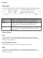
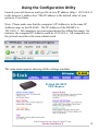
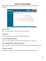
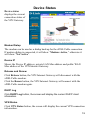
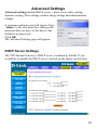
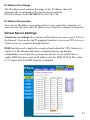
D-Link DI-804V
Broadband VPN Router
Manual
Rev. 031902
Building Networks for People
Contents
Package Contents .................................................... 3
Introduction............................................................... 4
IP Address Settings and Computer Settings ............ 8
Using the Configuration Utility .................................. 9
Basic Setup ............................................................ 10
Device Information.................................................. 18
Device Status ......................................................... 19
Advanced Settings.................................................. 20
System Tools .......................................................... 29
Configuring Your PCs to Connect to the DI-804V
Router..................................................................... 34
Networking Basics .................................................. 37
Contacting Technical Support................................. 49
Limited Warranty and Registration ......................... 50
2
Package Contents
Contents of Package:
•
•
•
•
D-Link DI-804V Broadband VPN Router
Manual
Quick Installation Guide
Power Adapter - 5V DC, 2A*
*Using a power supply with a different voltage rating will damage and void
the warranty for this product. If any of the above items are missing, please
contact your reseller
System Requirements:
Internet Explorer 4.0 or higher or Netscape Navigator 4.0 or higher, with JavaScript
enabled
One computer with an installed 10Mbps, 100Mbps or 10/100 Mbps Ethernet adapter
One Modem or ISDN TA (if a dial-up connection is needed)
One RJ-45 DSL/Cable Modem for Internet connection
3
Introduction
The D-Link DI-804V Broadband VPN Router enables your network to
connect to the Internet via a secure, private connection using a Cable/DSL
modem, such as the D-Link DCM-200 Cable Modem. The Virtual Private
Network that is created on the Internet between your home and your office
(with a VPN server) is secure from interference when you use the DI-804V.
It is an ideal way to connect your computer to a Local Area Network (LAN).
After completing the steps outlined in the Quick Install Guide (included in
your package) you will have the ability to share information and resources,
such as files and printers, and take full advantage of a “connected”
environment for work or play!
Connect the WAN port on the DI-804V to the Cable/DSL modem (e.g., the
DCM-200) using an Ethernet cable. Your entire LAN can now access the
Internet using just one Internet account. The DI-804V has 4 LAN ports.
That means that 4 computers can share the benefits of the DI-804V- equipped
network.
For the price of one Internet account, the DHCP-capable DI-804V will
automatically provide unique IP Addresses for all the computers on the
network. (DHCP stands for Dynamic Host Configuration Protocol. It is a
protocol for assigning IP Addresses automatically. With a DHCP router like
the DI-804V, there is no need to assign static IP Addresses, or purchase
multiple addresses from the ISP - Internet Service Provider.)
Everyone in your home can access the Internet on his or her own computer, at
the same time, without any noticeable decrease in speed.
With the serial port, you can connect an analog modem (dial-up modem) as a
back up in case of any difficulties that may arise with the Cable or DSL
connection.
With Firewall Protection, Hacker attack logging, and Virtual Private
Networking, the DI-804V provides a level of security suitable for many
businesses.
4
This manual provides a quick introduction to network technology. Please
take a moment to read through this manual and get acquainted with your
DI-804V.
Front View
LED Indicators
LAN (1-4)
LINK (Green)
Link/Act
ACT (Green)
Serial
(Green)
WAN
(Green)
Status
(Yellow)
Power
(Red)
Green LED will LIGHT when link is
established.
Green LED will BLINK when packet is
transmitting or receiving.
Green LED will LIGHT when a good link is
established.
Green LED will LIGHT when a good link is
established.
Yellow LED will BLINK when started up
and when firmware is upgraded.
Red LED will LIGHT when powered ON.
5
Rearview
Power (5V DC)
WAN
Serial
Ports 1-4
Reset
Connect the DC power adapter to the Power port
Connect DSL/Cable modem to the WAN Ethernet port
Connect a 56k modem/ISDN TA to the serial port
Connect networked devices such as computers and ftp
servers to the four LAN ports, which support auto
crossover
To reload the factory default settings, press the reset button
for 5-6 seconds. Pressing the Reset button will clear the
current data.
Product Features
VPN
Provides Virtual Private Networking when communicating with a VPN serverequipped office, or with another DI-804V-equipped network. Supports PPTP and
L2TP pass through function.
DSL/Cable Modem support
The DI-804V can connect any DSL/Cable Modem to the network.
DHCP
The DI-804V is a DHCP-capable router. It automatically assigns unique IP
Addresses to each network users that is connected to the DI-804V, for the price of
one Internet account.
6
Firewall Protection
Supports general hacker attack pattern monitoring and logging
PPPoE Client
Supports PPPoE client function to connect to the remote PPPoE server.
Virtual Server
Allows the internal server to be accessible from the Internet
Upgradeable New Features
Allows new features to be added in the future
High Performance 32 bit RISC CPU Engine
With the most advanced 32 bit RISC CPU Engine, DI-804V guarantees full
compatibility with future DSL/Cable technologies
IPSec Security
(DES, 3DES, MD5, SHA-1)
Idle Timer
Set a specified idle-time before automatically disconnecting
Dial-on Demand
Eliminates the need for Dial-up. Automatically logs in to your ISP
Serial port
May connect to a 56k modem or ISDN TA (should a Cable/DSL connection be
unavailable or fail.)
Web-Based Configuration
No software installation required. Can be configured through a web browser making
it OS independent
7
IP Address Settings and Computer Settings
In order to install the DI-804V you will need to check your computer’s
settings and the values from your ISP.
The information offered by your ISP:
•
•
•
•
•
Dynamic IP settings
Your fixed IP address for the gateway
Your subnet mask for the gateway
Your default gateway IP address
Your DNS IP address
If you would like to use PPPoE, you will need the following values from your
ISP in order to install your router:
•
•
User Name
Password
The static IP settings for the PC:
•
•
•
•
Your PC’s fixed IP address
Your PC’s subnet mask
Your PC’s default gateway
Your PC’s primary DNS IP address
Note: The router’s default IP address setting is 192.168.0.1.
Dynamic IP Settings:
The dynamic IP settings for the PC. It is recommended that you leave your IP
settings as automatically assigned. By default, the gateway is a DHCP server, and it
will give your computer the necessary IP settings.
8
Using the Configuration Utility
Launch your web browser and type the device IP address (http:// 192.168.0.1)
in the browser’s address box. This IP address is the default value of your
gateway. Press Enter.
Note: Please make sure that the computer’s IP Address is in the same IP
Address range as the DI-804V. The IP Address of the DI-804V is
192.168.0.1. All computers on your network must be within that range, for
instance, the computer IP Address could be 192.168.0.x. All computers on
the network must have the same subnet mask.
The main menu appears showing all the settings available.
9
Basic Setup
Basic setup is a step-by-step process that will let you input all the basic
settings.
Click BASIC SETUP
A username and password screen will appear. Leave the password box empty
and type admin (the default username) in the username box.
Click OK
The Setup Wizard’s page will appear.
Note: If you choose to input a password at any time, please remember it. If
you should lose the password, you will need to reset the unit. After you reset
the DI-804V, all your settings will be lost and will need to be re-input.
10
Time Settings
Please choose your local time zone.
Device IP Settings
You have to give your VPN Gateway an IP address on your network. This is
not the IP address from your ISP but the local internal LAN IP address. The
IP address “192.168.0.1” is the default value of your gateway.
Device IP Address:
The internal LAN IP
address of your VPN
Gateway.
Device IP Subnet Mask:
The subnet mask can
usually be left as its
default entry
“255.255.255.0”.
11
Cable/DSL ISP Settings
To use the xDSL/Cable ISP settings, you must configure the router. ISP use
either static or dynamic IP addresses. Check with your ISP if you are not
certain which one it uses. If your ISP uses a static IP address, it means that
the IP address of your router is always the same. Most ISPs use dynamic IP
addresses. They assign you a new IP address every time you connect to the
Internet.
If you have a static IP address, do the following:
Enter the IP address that your ISP provided.
Enter the IP subnet mask.
Enter the ISP gateway address.
Enter the DNS IP address.
12
ISP Additional Settings (PPPoE Settings)
You can configure the router to use additional ISP settings. Some ISPs
require PPPoE for authentication purposes.
Do the following to set up PPPoE:
User name: Enter the user name of your ISP account.
Password: Enter the password of your ISP account.
Retype password: Enter the password of your ISP account again to reconfirm.
Some ISPs use Host Name and Domain Name to authenticate the user; if this
is the case, you need to enter:
Host Name: Enter the name of the gateway.
Domain Name: Enter the domain name provided by your ISP
Some ISP require you input the LAN card Mac address; if this is the case,
you need to enter:
Mac Address: Enter this LAN card Mac address.
Note: Some ISPs may recognize your LAN card Mac address as a legal user;
in this case, you have to copy the LAN card Mac address in the Mac address
field.
For WIN 95/98 you can run winipcfg to see the LAN card Mac address.
For WIN/NT you can run ipconfig/all to see the LAN card Mac address.
13
Modem Settings
The modem dialup can be used as a backup for the xDSL/Cable connection.
If you would like to use the modem dialup or VPN features you must enable
the modem settings. Click on the Advanced Settings tab and enter the ISP
account information.
Note: If you would like to change the baud rate settings, please click on the
“ADVANCED SETTINGS”. Then click on the MODEM SETTINGS button.
Note: When your Cable/DSL connection comes back on-line, you will need to
return to this page and uncheck the backup dial-up modem setting in order to
use your Cable/DSL Broadband connection again.
14
VPN Settings
Use this screen to enable the IPSec feature. This feature allows a secure
connection between two parties. The connection is made over the Internet. To
enable the VPN function, check the Enable VPN checkbox and enter a string
into the connection name field, then click the “ADD” button.
Enabled NetBIOS Broadcast
Computers running Microsoft Windows can communicate with one another
using NetBIOS. Users can access remote network resources by browsing the
Window Network Neighborhood. You can uncheck the Enabled NetBIOS
Broadcast checkbox. The Secure Association (SA) can be created using IKE
(auto-mode) or Manual Mode. The default value is Internet Key Exchange
(IKE). If you would like to use Manual Key, check the Manual radio box and
required input fields will be shown.
15
Incoming SPI
Enter the Incoming SPI that the remote VPN Gateway will use to identify this
SA.
Outgoing SPI
Enter the Outgoing SPI that the local VPN Gateway will use identify this SA
Encryption Protocol
VPN Internet Gateway supports three encryption algorithms (Null, DES, or
3DES); user can select an appropriate encryption algorithm.
Encryption Key
This string is used as a key to encrypt and decrypt the data transmitted.
Authentication Protocol
VPN Internet Gateway supports two authentication algorithms (MD5 or
SHA-1); user can select an appropriate authentication algorithm.
Authentication Key
This string is used as key authentication.
16
Save & Restart
After you have finished making all the changes on the various pages, please
click Save & Restart to save the settings and restart the device. After the
restart, the device will function according to the saved settings.
During the startup process the LED of the device will blink. Please wait until
the blinking of the device stops before proceeding.
17
Device Information
Device information displays the current settings of the VPN Internet
Gateway.
Device Name
This is the host name of the VPN Internet Gateway.
IP Address
This is the IP address of the VPN Internet Gateway.
Private LAN Mac Address
This is the Mac address of the VPN Internet Gateway LAN port.
Public WAN (xDSL/Cable) Mac Address
This is the Mac Address of the VPN Internet Gateway WAN Ethernet port.
Firmware version
Displays the Firmware Version of the DI-804V and its release date
18
Device Status
Device status
displays the current
connection status of
the VPN Gateway.
Modem Dialup
The modem can be used as a dialup backup for the xDSL/Cable connection.
If modem dialup is connected, it will show “Modem: Active,” otherwise it
will show “Not Active”.
Device IP
Shows the Device IP address, private LAN Mac address and public WAN
Mac address of the VPN Internet Gateway.
Release and Renew
Click Release button, the VPN Internet Gateway will disconnect with the
xDSL/Cable modem.
Click the Renew button, the VPN Internet Gateway will connect with the
xDSL/Cable modem again.
DHCP Log
Click DHCP Log button, the screen will display the current DHCP client
information.
VPN Status
Click VPN Status button, the screen will display the current VPN connection
information.
19
Advanced Settings
Advanced settings include DHCP server, virtual server static routing,
dynamic routing, filter settings, modem string settings and administration
settings.
A username and password will appear. Type
“admin” in the user name box, and type the
password that you have set the device (the
default is no password)
Click OK
The Advanced Settings page will appear.
DHCP Server Settings
The VPN Internet Gateway’s DHCP server is enabled by default. If you
would like to disable the DHCP server, unclick on the square circle below.
20
IP Address Pool Range
The IP address pool contains the range of the IP address that will
automatically be assigned to the clients of your network.
Default setting is from 192.168.2.2 to 192.168.2.100.
IP Address Reservation
You can use IP address reservation option to give particular computers on
your network the same static IP address every time the computer is turned on.
Virtual Server Settings
Virtual server settings allow clients on the Internet to access your LAN via
the Internet. You can use the IP mapping function to access an FTP server or
Telnet server etc. remotely through Internet.
DMZ function can be applied to a single client behind the VPN Gateway to
expose it to the Internet and ensure complete Internet application
compatibility even if specific ports are not known. If you would like to
enable DMZ function, enter an IP address into the DMZ IP field. The value
of ‘0’ means that the DMZ function is disabled.
21
Static Routing
Static routing settings allow the VPN Internet Gateway to route IP packets
to another network. The routing table stores the routing information so that
your network device knows where to redirect the IP packets to the proper
network.
Destination IP Address
The destination IP is the address of the remote network to which you want to
assign a static route.
Subnet Mask
The subnet mask of your network IP address.
Gateway IP Address
The IP address of the interface used to link to the remote network.
Dynamic Routing
Dynamic Routing Settings allow the VPN Internet Gateway to route IP
packets to another network automatically. The RIP protocol is applied, and
broadcasts the routing information to other routers on the network regularly.
22
For the SEND option choosing the proper protocol by which you transmit
the data on the network.
For the RECEIVE option choosing the proper protocol by which the VPN
Internet Gateway receive the data on the network.
Filter Settings – LAN Filter Settings
LAN Filter Settings allow administrator to define whether local user has the
permission to access Internet. To activate this feature, check LAN Side Filter
Enabled. Then, you can define the filtering policy by entering an IP address
range, network port number and select the protocol(s).
For example, to prevent the local user of IP address range (from 101 to 200)
to access port 80 (HTTP), the settings are as follows,
LAN Side Filter Enabled: Enabled
Default LAN Side Filter: Pass
Filter: Block
Protocol: TCP
IP Address Range: 101 ~ 200
Destination Port Range: 80 ~ 80 (HTTP)
23
Filter Settings – WAN Filter Settings
WAN Filter Settings allow administrator to define whether remote/outside
user has the permission to access the local network. To activate this feature,
check WAN Side Filter Enabled. Then, you can define the filtering policy
by entering IP address range, the port range and select the protocol(s).
For example, to prevent the remote user of IP address range (211.21.0.1 to
211.29.0.1) to access virtual WEB server (port 80), the setting are as follows,
WAN Side Filter Enabled: Enabled
Default WAN Side Filter: Pass
Filter: Block
Protocol: TCP
IP Address Range: 211.21.0.1 to 211.29.0.1
Destination Port Range: 80 ~ 80 (HTTP)
24
Modem String Settings
Modem string settings allow user to input detail settings for the analog
modem. If you would like to change the baud rate settings, please check the
initial string. (You can refer to the manual for your modem.)
Administration Settings
PASSWORD SETTINGS
You can give your VPN Gateway a new password. This password will be
required the next time you configure your VPN Gateway. To enter a
password, type your password in the new password field and type it again in
the retype password field.
Note: it is important to remember your password. If for any reason you lose
or forget your password, press the small reset button located on the back of
the device for 5 to 6 seconds. Reset action will re-initialize the settings. All
configurations, including password, will be reset and require re-entering.
25
SYSTEM ADMINISTRATION
Here, remote users can be set up to configure and administrate the VPN
Internet Gateway through Internet. The default value of HTTP port is 80.
The default IP address of remote administration host is: 0.0.0.0. (IP address
of 0.0.0.0 means that any PC on the network can remote access and manage
the VPN Internet Gateway).
If you use this function, you have to enable the feature “Allow remote user to
configure the device” first. Once you have enabled this function, type the
VPN Internet Gateway WAN IP address (http://192.168.100.1:1023) into the
browser of any or specific PC on the network.
26
Note: Once HTTP port no (NOT PORT 80) is changed and the users of the
LAN terminal want to configure the VPN Internet Gateway, the users have to
type the VPN Internet Gateway LAN IP address with port number
(http://192.168.0.1:1023).
System Parameters
System Parameters allows user to setup the MTU value (Maximum
Transmission Unit). The default MTU value is 1500 Bytes. User can setup a
proper MTU for your network device.
For some areas, the ISPs set the limit packet size for PPPoE connection. User
has to change MTU setting for surfing the net.
27
Save & Restart
If you have finished making all the changes on the various pages, please click
Save & Restart to save the settings and restart the device. If you would like to
configure the setting again, you can browse those functions then click them.
After the restart, the device will function according to the saved settings.
Save & Restart lets you save the input settings to the VPN Internet Gateway
(so as to be retrieved at a later time) and then restart it.
28
System Tools
System Tools
Detects the status of the VPN Internet Gateway.
Intruder Detection Log
The event messages show the possible hacker attacks that have occurred on
your VPN Gateway. Up to 32 hacker attacks may be logged in this manner.
Display Routing Table
The Display Routing Table shows the current static routing configuration.
29
System Diagnostics
System diagnostics shows your VPN Gateway’s information. It will perform
a check-up on your VPN Gateway to make sure that everything is functioning
properly.
30
Save Settings
This allows you to save the configuration to a file. If you would like to do
this, click Save File to save your current settings to a file. Then click save this
file to disk in the browsing wizard.
31
Load Settings - Load Default Settings
This allows you to load the original default settings of your VPN Internet
Gateway.
Load Settings - Load Settings From File
This allows you to load the settings from a file.
32
Upgrade Firmware
The upgrade firmware option allows you to upgrade the latest firmware to
your VPN Internet Gateway.
Reset Device
Resetting the device will restart it. Click on the START button to restart.
33
Configuring Your PCs to Connect
to the DI-804V Router
If you do not wish to set the static IP address on your PC, you will need to
configure your PC to request an IP address from the gateway.
Click the Start button, select Settings, select Control Panel.
Double-click the Network icon.
In the configuration tab, select the TCP/IP protocol line that has been
associated with your network card/adapter. If there is no TCP/IP line listed,
you will need to install TCP/IP now.
34
Click the Properties button, then choose the IP ADDRESS tab. Select
Obtain an IP automatically.
After clicking OK, windows might ask you to restart the PC. Click Yes.
CONFIRM YOUR PC’S IP CONFIGURATION
There are two tools which are great for finding out a computer’s IP
configuration: MAC address and default gateway.
•
WINIPCFG (for Windows 95/98)
Inside the windows 95/98 Start button, select Run and type winipcfg. In the
example below this computer has an IP address of 192.168.0.100 and the
default gateway is 192.168.0.1. The default gateway should be the network
device IP address. The MAC address in windows 95/98 is called the Adapter
Address.
NOTE: You can also type winipcfg in the DOS command prompt.
35
•
IPCONFIG (for Windows 2000/NT/XP)
In the DOS command prompt type IPCONFIG and press Enter. Your PC IP
information will be displayed as shown below.
36
Networking Basics
Using the Network Setup Wizard in Windows XP
In this section you will learn how to establish a network at home or work,
using Microsoft Windows XP.
Note: Please refer to websites such as http://www.homenethelp.com
and http://www.microsoft.com/windows2000 for information about
networking computers using Windows 2000, ME or 98.
Go to START>CONTROL PANEL>NETWORK CONNECTIONS
Select Set up a home or small office network
When this screen appears, Click Next.
37
Please follow all the instructions in this window:
Click Next
In the following window, select the best description of your computer. If
your computer connects to the Internet through a gateway/router, select the
second option as shown.
Click Next
38
Enter a Computer description and a Computer name (optional.)
Click Next
Enter a Workgroup name. All computers on your network should have the
same Workgroup name.
Click Next
39
Please wait while the wizard applies the changes.
When the changes are complete, Click Next.
Please wait while the wizard configures the computer.
This may take a few minutes.
40
In the window below, select the best option. In this example, “Create a
Network Setup Disk” has been selected. You will run this disk on each of the
computers on your network. Click Next.
Insert a disk into the Floppy Disk Drive, in this case drive “A:”
Format the disk if you wish, and Click Next.
41
Please wait while the wizard copies the files.
Please read the information under Here’s how in the screen below. After you
complete the Network Setup Wizard you will use the Network Setup Disk to
run the Network Setup Wizard once on each of the computers on your
network.
To continue Click Next
42
Please read the information on this screen, then Click Finish to complete the
Network Setup Wizard.
The new settings will take effect when you restart the computer. Click Yes to
restart the computer.
You have completed configuring this computer. Next, you will need to run
the Network Setup Disk on all the other computers on your network. After
running the Network Setup Disk on all your computers, your new wireless
network will be ready to use.
43
Naming your Computer
Naming your computer is optional. If you would like to name your computer
please follow these directions:
In Windows XP:
Click START (in the
lower left corner of the
screen)
Right-click on My
Computer
Select Properties
•
Select the
Computer Name
Tab in the System
Properties window.
You may enter a
Computer description if
you wish, this field is
optional.
To rename the computer
and join a domain,
• Click Change
44
•
In this window, enter
the Computer
name.
•
Select Workgroup
and enter the name
of the Workgroup.
•
All computers on
your network must
have the same
Workgroup name.
•
Click OK
45
Assigning a Static IP Address
Note: Residential Gateways/Broadband Routers will automatically assign IP
Addresses to the computers on the network, using DHCP (Dynamic Host
Configuration Protocol) technology. If you are using a DHCP-capable
Gateway/Router you will not need to assign Static IP Addresses.
If you are not using a DHCP capable Gateway/Router, or you need to assign a
Static IP Address, please follow these instructions:
Go to START
Double-click on
Control Panel
Double-click on
Network Connections
46
Right-click on Local Area
Connections.
Double-click Properties
Highlight Internet Protocol
(TCP/IP)
Click Properties
47
Select Use the following IP address in the Internet Protocol (TCP/IP)
Properties window.
Input your IP address and subnet mask. (The IP Addresses on your network
must be within the same range. For example, if one computer has an IP
Address of 192.168.0.2, the other computers should have IP Addresses that
are sequential, like 192.168.0.3 and 192.168.0.4. The subnet mask must be
the same for all the computers on the network.)
Input your DNS server addresses.
The DNS server information will be provided by your ISP (Internet Service
Provider.)
Click OK
You have completed the assignment of a Static IP Address. (You do not need
to assign a Static IP Address if you have a DHCP-capable Gateway/Router.)
48
Contacting Technical Support
You can find the most recent software and user documentation on the D-Link
website.
D-Link provides free technical support for customers within the United States for the
duration of the warranty period on this product.
U.S. customers can contact D-Link technical support through our web site,
or by phone.
D-Link Technical Support over the Telephone:
(800) 758-5489
24 hours a day, seven days a week.
D-Link Technical Support over the Internet:
http://support.dlink.com
When contacting technical support, please provide the following information:
Serial number of the unit
Model number or product name
Software type and version number
49
Limited Warranty and
Registration
D-Link Systems, Inc. (“D-Link”) provides this 1-Year warranty for its product only to the person or entity who
originally purchased the product from:
•
•
D-Link or its authorized reseller or distributor.
Products purchased and delivered with the fifty United States, the District of Columbia, US Possessions
or Protectorates, US Military Installations, addresses with an APO or FPO.
1-Year Limited Hardware Warranty: D-Link warrants that the hardware portion of the D-Link products
described below (“Hardware”) will be free from material defects in workmanship and materials from the date of
original retail purchase of the Hardware, for the period set forth below applicable to the product type (“Warranty
Period”).
1-Year Limited Warranty for the Product(s) is defined as follows
•
Hardware (including power supplies and fans) One (1) Year
•
Spare parts and spare kits Ninety (90) days.
D-Link’s sole obligation shall be to repair or replace the defective Hardware at no charge to the original owner.
Such repair or replacement will be rendered by D-Link at an Authorized D-Link Service Office. The replacement
Hardware need not be new or of an identical make, model or part; D-Link may in its discretion replace the defective
Hardware (or any part thereof) with any reconditioned product that D-Link reasonably determines is substantially
equivalent (or superior) in all material respects to the defective Hardware. The Warranty Period shall extend for an
additional ninety (90) days after any repaired or replaced Hardware is delivered. If a material defect is incapable of
correction, or if D-Link determines in its sole discretion that it is not practical to repair or replace the defective
Hardware, the price paid by the original purchaser for the defective Hardware will be refunded by D-Link upon
return to D-Link of the defective Hardware. All Hardware (or part thereof) that is replaced by D-Link, or for which
the purchase price is refunded, shall become the property of D-Link upon replacement or refund.
Limited Software Warranty: D-Link warrants that the software portion of the product (“Software”) will
substantially conform to D-Link’s then current functional specifications for the Software, as set forth in the
applicable documentation, from the date of original delivery of the Software for a period of ninety (90) days
(“Warranty Period”), if the Software is properly installed on approved hardware and operated as contemplated in its
documentation. D-Link further warrants that, during the Warranty Period, the magnetic media on which D-Link
delivers the Software will be free of physical defects. D-Link’s sole obligation shall be to replace the nonconforming Software (or defective media) with software that substantially conforms to D-Link’s functional
specifications for the Software. Except as otherwise agreed by D-Link in writing, the replacement Software is
provided only to the original licensee, and is subject to the terms and conditions of the license granted by D-Link for
the Software. The Warranty Period shall extend for an additional ninety (90) days after any replacement Software is
delivered. If a material non-conformance is incapable of correction, or if D-Link determines in its sole discretion
that it is not practical to replace the non-conforming Software, the price paid by the original licensee for the nonconforming Software will be refunded by D-Link; provided that the non-conforming Software (and all copies
thereof) is first returned to D-Link. The license granted respecting any Software for which a refund is given
automatically terminates.
What You Must Do For Warranty Service:
Registration is conducted via a link on our Web Site (http://www.dlink.com/). Each product purchased must be
individually registered for warranty service within ninety (90) days after it is purchased and/or licensed.
FAILURE TO PROPERLY TO REGISTER MAY AFFECT THE WARRANTY FOR THIS PRODUCT.
Submitting A Claim. Any claim under this limited warranty must be submitted in writing before the end of the
Warranty Period to an Authorized D-Link Service Office.
•
The customer must submit as part of the claim a written description of the Hardware defect or Software
nonconformance in sufficient detail to allow D-Link to confirm the same.
50
•
The original product owner must obtain a Return Material Authorization (RMA) number from the
Authorized D-Link Service Office and, if requested, provide written proof of purchase of the product (such as a
copy of the dated purchase invoice for the product) before the warranty service is provided.
•
After an RMA number is issued, the defective product must be packaged securely in the original or other
suitable shipping package to ensure that it will not be damaged in transit, and the RMA number must be
prominently marked on the outside of the package.
•
The customer is responsible for all shipping charges to and from D-Link (No CODs allowed). Products
sent COD will become the property of D-Link Systems, Inc. Products should be fully insured by the customer
and shipped to D-Link Systems Inc., 53 Discovery Drive, Irvine CA 92618.
D-Link may reject or return any product that is not packaged and shipped in strict compliance with the foregoing
requirements, or for which an RMA number is not visible from the outside of the package. The product owner
agrees to pay D-Link’s reasonable handling and return shipping charges for any product that is not packaged and
shipped in accordance with the foregoing requirements, or that is determined by D-Link not to be defective or nonconforming.
What Is Not Covered:
This limited warranty provided by D-Link does not cover: Products that have been subjected to abuse, accident,
alteration, modification, tampering, negligence, misuse, faulty installation, lack of reasonable care, repair or service
in any way that is not contemplated in the documentation for the product, or if the model or serial number has been
altered, tampered with, defaced or removed; Initial installation, installation and removal of the product for repair,
and shipping costs; Operational adjustments covered in the operating manual for the product, and normal
maintenance; Damage that occurs in shipment, due to act of God, failures due to power surge, and cosmetic damage;
and Any hardware, software, firmware or other products or services provided by anyone other than D-Link.
Disclaimer of Other Warranties: EXCEPT FOR THE 1-YEAR LIMITED WARRANTY SPECIFIED HEREIN,
THE PRODUCT IS PROVIDED “AS-IS” WITHOUT ANY WARRANTY OF ANY KIND INCLUDING,
WITHOUT LIMITATION, ANY WARRANTY OF MERCHANTABILITY, FITNESS FOR A PARTICULAR
PURPOSE AND NON-INFRINGEMENT. IF ANY IMPLIED WARRANTY CANNOT BE DISCLAIMED IN
ANY TERRITORY WHERE A PRODUCT IS SOLD, THE DURATION OF SUCH IMPLIED WARRANTY
SHALL BE LIMITED TO NINETY (90) DAYS. EXCEPT AS EXPRESSLY COVERED UNDER THE LIMITED
WARRANTY PROVIDED HEREIN, THE ENTIRE RISK AS TO THE QUALITY, SELECTION AND
PERFORMANCE OF THE PRODUCT IS WITH THE PURCHASER OF THE PRODUCT.
Limitation of Liability: TO THE MAXIMUM EXTENT PERMITTED BY LAW, D-LINK IS NOT LIABLE
UNDER ANY CONTRACT, NEGLIGENCE, STRICT LIABILITY OR OTHER LEGAL OR EQUITABLE
THEORY FOR ANY LOSS OF USE OF THE PRODUCT, INCONVENIENCE OR DAMAGES OF ANY
CHARACTER, WHETHER DIRECT, SPECIAL, INCIDENTAL OR CONSEQUENTIAL (INCLUDING, BUT
NOT LIMITED TO, DAMAGES FOR LOSS OF GOODWILL, WORK STOPPAGE, COMPUTER FAILURE OR
MALFUNCTION, LOSS OF INFORMATION OR DATA CONTAINED IN, STORED ON, OR INTEGRATED
WITH ANY PRODUCT RETURNED TO D-LINK FOR WARRANTY SERVICE) RESULTING FROM THE
USE OF THE PRODUCT, RELATING TO WARRANTY SERVICE, OR ARISING OUT OF ANY BREACH OF
THIS LIMITED WARRANTY, EVEN IF D-LINK HAS BEEN ADVISED OF THE POSSIBILITY OF SUCH
DAMAGES. THE SOLE REMEDY FOR A BREACH OF THE FOREGOING LIMITED WARRANTY IS
REPAIR, REPLACEMENT OR REFUND OF THE DEFECTIVE OR NON-CONFORMING PRODUCT.
GOVERNING LAW: This 1-Year Warranty shall be governed by the laws of the state of California. Some states do
not allow exclusion or limitation of incidental or consequential damages, or limitations on how long an implied
warranty lasts, so the foregoing limitations and exclusions may not apply. This limited warranty provides specific
legal rights and the product owner may also have other rights which vary from state to state.
Trademarks
Copyright® 2001 D-Link Corporation. Contents subject to change without prior notice. D-Link is a registered
trademark of D-Link Corporation/D-Link Systems, Inc. All other trademarks belong to their respective proprietors.
Copyright Statement
No part of this publication may be reproduced in any form or by any means or used to make any derivative such as
translation, transformation, or adaptation without permission from D-Link Corporation/D-Link Systems Inc., as
stipulated by the United States Copyright Act of 1976.
CE Mark Warning
This is a Class B product. In a domestic environment, this product may cause radio interference, in which case the
user may be required to take adequate measures.
FCC Statement
This equipment has been tested and found to comply with the limits for a Class B digital device, pursuant to part 15
of the FCC Rules. These limits are designed to provide reasonable protection against harmful interference in a
residential installation. This equipment generates uses and can radiate radio frequency energy and, if not installed
and used in accordance with the instructions, may cause harmful interference to radio communication. However,
there is no guarantee that interference will not occur in a particular installation. If this equipment does cause harmful
51
interference to radio or television reception, which can be determined by turning the equipment off and on, the user
is encouraged to try to correct the interference by one or more of the following measures:
•
Reorient or relocate the receiving antenna.
•
Increase the separation between the equipment and receiver.
•
Connect the equipment into an outlet on a circuit different from that to which the receiver is connected.
•
Consult the dealer or an experienced radio/TV technician for help.
Register Your D-Link Product Online at http://www.dlink.com/sales/reg
52