1
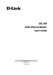
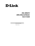
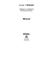
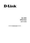
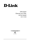
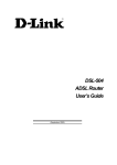
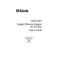
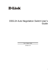
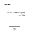
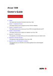
D-Link DGS-1024T
24-Port 10/100/100Mbps with 2 Combo SFP Ports
Gigabit Ethernet Switch
Manual
First Edition
Building Networks for People
RECYCLABLE
D-Link DGS-1024T Unmanaged Gigabit Ethernet Switch
CONTENTS
PREFACE............................................................................................................................................................ III
INTENDED READERS ........................................................................................................................................... III
NOTES, NOTICES, AND CAUTIONS............................................................................................................. III
SAFETY INSTRUCTIONS................................................................................................................................ IV
Safety Cautions................................................................................................................................................iv
General Precautions for Rack-Mountable Products ........................................................................................v
Protecting Against Electrostatic Discharge....................................................................................................vi
INTRODUCTION..................................................................................................................................................7
ETHERNET TECHNOLOGY ......................................................................................................................................7
Fast Ethernet Technology ................................................................................................................................7
Gigabit Ethernet Technology ...........................................................................................................................7
SWITCHING TECHNOLOGY ....................................................................................................................................7
SWITCH DESCRIPTION ...........................................................................................................................................8
Features ...........................................................................................................................................................8
Ports .................................................................................................................................................................9
FRONT-PANEL COMPONENTS ................................................................................................................................9
LED Indicators.................................................................................................................................................9
REAR PANEL DESCRIPTION .................................................................................................................................10
SIDE PANEL DESCRIPTION...................................................................................................................................10
GIGABIT COMBO PORTS ......................................................................................................................................11
INSTALLATION .................................................................................................................................................12
Package Contents...........................................................................................................................................12
BEFORE YOU CONNECT TO THE NETWORK .........................................................................................................12
INSTALLING THE SWITCH WITHOUT THE RACK...................................................................................................13
INSTALLING THE SWITCH IN A RACK ...................................................................................................................13
Mounting the Switch in a standard 19” rack. ................................................................................................14
POWER ON ..........................................................................................................................................................14
Power Failure ................................................................................................................................................14
CONNECTING THE SWITCH .........................................................................................................................15
SWITCH TO END NODE .......................................................................................................................................15
SWITCH TO HUB OR SWITCH ...............................................................................................................................15
CONNECTING TO NETWORK BACKBONE OR SERVER ..........................................................................................16
TECHNICAL SPECIFICATIONS.....................................................................................................................17
GLOSSARY..........................................................................................................................................................19
D-Link DGS-1024T Unmanaged Gigabit Ethernet Switch
Preface
The DGS-1024T Manual is divided into sections that describe the system installation and operating instructions
with examples.
Section 1, Introduction - A description of the physical features of the switch, including LED indicators,
ports and panel descriptions.
Section 2, Installation – A description of the physical installation of the switch including connecting the
switch to the network and connecting stacked switch groups.
Section 3, Connecting the switch – A description of how to connect your switch to an end node, hub,
switch or backbone server.
Appendix A, Technical Specifications - The technical specifications of the DGS-1024T.
Glossary – Lists definitions for terms and acronyms used in this document.
Index – Index of relevant terms in the DGS-1024T Manual.
Intended Readers
The DGS-1024T Manual contains information for setup and management and of the DGS-1024T switch. This
guide is intended for network managers familiar with network management concepts and terminology.
Notes, Notices, and Cautions
NOTE: A NOTE indicates important information that helps you make
better use of your device.
NOTICE: A NOTICE indicates either potential damage to hardware or loss
of data and tells you how to avoid the problem.
CAUTION: A CAUTION indicates the potential for property damage,
personal injury, or death.
iii
D-Link DGS-1024T Unmanaged Gigabit Ethernet Switch
Safety Instructions
Use the following safety guidelines to ensure your own personal safety and to help protect your system from
potential damage. Throughout this safety section, the caution icon (
) is used to indicate cautions and
precautions that you need to review and follow.
Safety Cautions
To reduce the risk of bodily injury, electrical shock, fire, and damage to the equipment, observe the following
precautions.
Observe and follow service markings. Do not service any product except as explained in your system
documentation. Opening or removing covers that are marked with the triangular symbol with a lightning bolt
may expose you to an electrical shock. Only a trained service technician should service components inside these
compartments.
If any of the following conditions occur, unplug the product from the electrical outlet and replace the part or
contact your trained service provider:
– The power cable, extension cable, or plug is damaged.
– An object has fallen into the product.
– The product has been exposed to water.
– The product has been dropped or damaged.
– The product does not operate correctly when you follow the operating instructions.
•
Keep your system away from radiators and heat sources. Also, do not block cooling vents.
•
Do not spill food or liquids on your system components, and never operate the product in a wet
environment. If the system gets wet, see the appropriate section in your troubleshooting guide or contact
your trained service provider.
•
Do not push any objects into the openings of your system. Doing so can cause a fire or an electric shock
by shorting out interior components.
•
Use the product only with approved equipment.
•
Allow the product to cool before removing covers or touching internal components.
•
Operate the product only from the type of external power source indicated on the electrical ratings label.
If you are not sure of the type of power source required, consult your service provider or local power
company.
•
To help avoid damaging your system, be sure the voltage selection switch (if provided) on the power
supply is set to match the power available at your location:
– 115 volts (V)/60 hertz (Hz) in most of North and South America and some Far Eastern countries such
as South Korea and Taiwan
– 100 V/50 Hz in eastern Japan and 100 V/60 Hz in western Japan
– 230 V/50 Hz in most of Europe, the Middle East, and the Far East
•
Also be sure that attached devices are electrically rated to operate with the power available in your
location.
iv
D-Link DGS-1024T Unmanaged Gigabit Ethernet Switch
Safety Instructions (continued)
•
Use only approved power cable(s). If you have not been provided with a power cable for your system or
for any AC-powered option intended for your system, purchase a power cable that is approved for use in
your country. The power cable must be rated for the product and for the voltage and current marked on
the product's electrical ratings label. The voltage and current rating of the cable should be greater than
the ratings marked on the product.
•
To help prevent an electric shock, plug the system and peripheral power cables into properly grounded
electrical outlets. These cables are equipped with three-prong plugs to help ensure proper grounding. Do
not use adapter plugs or remove the grounding prong from a cable. If you must use an extension cable,
use a 3-wire cable with properly grounded plugs.
•
Observe extension cable and power strip ratings. Make sure that the total ampere rating of all products
plugged into the extension cable or power strip does not exceed 80 percent of the ampere ratings limit
for the extension cable or power strip.
•
To help protect your system from sudden, transient increases and decreases in electrical power, use a
surge suppressor, line conditioner, or uninterruptible power supply (UPS).
•
Position system cables and power cables carefully; route cables so that they cannot be stepped on or
tripped over. Be sure that nothing rests on any cables.
•
Do not modify power cables or plugs. Consult a licensed electrician or your power company for site
modifications. Always follow your local/national wiring rules.
•
When connecting or disconnecting power to hot-pluggable power supplies, if offered with your system,
observe the following guidelines:
– Install the power supply before connecting the power cable to the power supply.
– Unplug the power cable before removing the power supply.
– If the system has multiple sources of power, disconnect power from the system by
unplugging all power cables from the power supplies.
•
Move products with care; ensure that all casters and/or stabilizers are firmly connected to the system.
Avoid sudden stops and uneven surfaces.
General Precautions for Rack-Mountable Products
Observe the following precautions for rack stability and safety. Also refer to the rack installation documentation
accompanying the system and the rack for specific caution statements and procedures.
Systems are considered to be components in a rack. Thus, "component" refers to any system as well as to various
peripherals or supporting hardware.
CAUTION: Installing systems in a rack without the front and side stabilizers
installed could cause the rack to tip over, potentially resulting in bodily injury under
certain circumstances. Therefore, always install the stabilizers before installing
components in the rack.
After installing system/components in a rack, never pull more than one component
out of the rack on its slide assemblies at one time. The weight of more than one
extended component could cause the rack to tip over and may result in serious
injury.
•
Before working on the rack, make sure that the stabilizers are secured to the rack, extended to the floor,
and that the full weight of the rack rests on the floor. Install front and side stabilizers on a single rack or
front stabilizers for joined multiple racks before working on the rack.
v
D-Link DGS-1024T Unmanaged Gigabit Ethernet Switch
Safety Instructions (continued)
Always load the rack from the bottom up, and load the heaviest item in the rack first.
Make sure that the rack is level and stable before extending a component from the rack.
Use caution when pressing the component rail release latches and sliding a component into or out of a rack; the
slide rails can pinch your fingers.
After a component is inserted into the rack, carefully extend the rail into a locking position, and then slide the
component into the rack.
Do not overload the AC supply branch circuit that provides power to the rack. The total rack load should not
exceed 80 percent of the branch circuit rating.
Ensure that proper airflow is provided to components in the rack.
Do not step on or stand on any component when servicing other components in a rack.
NOTE: A qualified electrician must perform all connections to DC power and to
safety grounds. All electrical wiring must comply with applicable local or national
codes and practices.
CAUTION: Never defeat the ground conductor or operate the equipment in the
absence of a suitably installed ground conductor. Contact the appropriate electrical
inspection authority or an electrician if you are uncertain that suitable grounding is
available.
CAUTION: The system chassis must be positively grounded to the rack cabinet
frame. Do not attempt to connect power to the system until grounding cables are
connected. Completed power and safety ground wiring must be inspected by a
qualified electrical inspector. An energy hazard will exist if the safety ground cable
is omitted or disconnected.
Protecting Against Electrostatic Discharge
Static electricity can harm delicate components inside your system. To prevent static damage, discharge static
electricity from your body before you touch any of the electronic components, such as the microprocessor. You
can do so by periodically touching an unpainted metal surface on the chassis.
You can also take the following steps to prevent damage from electrostatic discharge (ESD):
1. When unpacking a static-sensitive component from its shipping carton, do not remove the component
from the antistatic packing material until you are ready to install the component in your system. Just
before unwrapping the antistatic packaging, be sure to discharge static electricity from your body.
2. When transporting a sensitive component, first place it in an antistatic container or packaging.
3. Handle all sensitive components in a static-safe area. If possible, use antistatic floor pads, workbench
pads and an antistatic grounding strap.
vi
D-Link DGS-1024T Unmanaged Gigabit Ethernet Switch
SECTION 1
Introduction
Ethernet Technology
Switch Description
Features
Ports
Front-Panel Components
Side Panel Description
Rear Panel Description
Gigabit Combo Ports
Ethernet Technology
Fast Ethernet Technology
The growing importance of LANs and the increasing complexity of desktop computing applications are fueling
the need for high performance networks. A number of high-speed LAN technologies are proposed to provide
greater bandwidth and improve client/server response times. Among them, Fast Ethernet, or 100BASE-T,
provides a non-disruptive, smooth evolution from 10BASE-T technology.
100Mbps Fast Ethernet is a standard specified by the IEEE 802.3 LAN committee. It is an extension of the
10Mbps Ethernet standard with the ability to transmit and receive data at 100Mbps, while maintaining the
Carrier Sense Multiple Access with Collision Detection (CSMA/CD) Ethernet protocol.
Gigabit Ethernet Technology
Gigabit Ethernet is an extension of IEEE 802.3 Ethernet utilizing the same packet structure, format, and support
for CSMA/CD protocol, full duplex, flow control, and management objects, but with a tenfold increase in
theoretical throughput over 100Mbps Fast Ethernet and a one hundred-fold increase over 10Mbps Ethernet.
Since it is compatible with all 10Mbps and 100Mbps Ethernet environments, Gigabit Ethernet provides a
straightforward upgrade without wasting a company’s existing investment in hardware, software, and trained
personnel.
The increased speed and extra bandwidth offered by Gigabit Ethernet are essential to coping with the network
bottlenecks that frequently develop as computers and their busses get faster and more users use applications that
generate more traffic. Upgrading key components, such as your backbone and servers to Gigabit Ethernet can
greatly improve network response times as well as significantly speed up the traffic between your subnetworks.
Gigabit Ethernet enables fast connections to support video conferencing, complex imaging, and similar dataintensive applications. Likewise, since data transfers occur 10 times faster than Fast Ethernet, servers outfitted
with Gigabit Ethernet NIC’s are able to perform 10 times the number of operations in the same amount of time.
In addition, the phenomenal bandwidth delivered by Gigabit Ethernet is the most cost-effective method to take
advantage of today and tomorrow’s rapidly improving switching and routing internetworking technologies.
Switching Technology
Another key development pushing the limits of Ethernet technology is in the field of switching technology. A
switch bridges Ethernet packets at the MAC address level of the Ethernet protocol transmitting among connected
Ethernet or fast Ethernet LAN segments.
Switching is a cost-effective way of increasing the total network capacity available to users on a local area
network. A switch increases capacity and decreases network loading by making it possible for a local area
network to be divided into different segments that do not compete with each other for network transmission
capacity, giving a decreasing the load on each segment.
7
D-Link DGS-1024T Unmanaged Gigabit Ethernet Switch
The switch acts as a high-speed selective bridge between the individual segments. Traffic that needs to go from
one segment to another is automatically forwarded by the switch, without interfering with any other segments.
This allows the total network capacity to be multiplied, while still maintaining the same network cabling and
adapter cards.
For Fast Ethernet or Gigabit Ethernet networks, a switch is an effective way of eliminating problems of chaining
hubs beyond the “two-repeater limit.” A switch can be used to split parts of the network into different collision
domains, for example, making it possible to expand your Fast Ethernet network beyond the 205-meter network
diameter limit for 100BASE-TX networks. Switches supporting both traditional 10Mbps Ethernet and 100Mbps
Fast Ethernet are also ideal for bridging between existing 10Mbps networks and new 100Mbps networks.
Switching LAN technology is a marked improvement over the previous generation of network bridges, which
were characterized by higher latencies. Routers have also been used to segment local area networks, but the cost
of a router and the setup and maintenance required make routers relatively impractical. Today’s switches are an
ideal solution to most kinds of local area network congestion problems.
Switch Description
The DGS-1024T Switch unit is equipped with twenty-four ports providing dedicated 10, 100 or 1000 Mbps
bandwidth. These ports can be used for connecting PCs, servers, hubs and other Ethernet devices. The twentyfour tri-speed ports use standard twisted pair cabling and are ideal for segmenting networks into small, connected
subnets. Each port can support up to 2000 Mbps of throughput in full-duplex mode. In addition, the Switch is
equipped with two Mini GBIC ports enabling fiber optic access to a server or network backbone for all the
clients served by the Switch. This stand-alone Switch enables the network to use some of the most demanding
multimedia and imaging applications concurrently with other user applications without creating bottlenecks.
Features
•
Twenty-four 10/100/1000BASE-T Gigabit ports for connections to server or network backbone
•
IEEE 802.3 compliant
•
IEEE 802.3ab compliant
•
IEEE 802.3u compliant
•
IEEE 802.3z compliant
•
IEEE 802.3x flow control for full duplex mode
•
Full and half-duplex for both 10Mbps and 100Mbps connections. The 1000BASE-T Gigabit Ethernet
module operates at full-duplex only. Full-duplex allows the switch port to simultaneously transmit and
receive data, and only works with connections to full-duplex capable end stations and switches.
Connections to a hub must take place at half-duplex
•
Store and forward switching scheme capability to support rate adaptation and protocol conversion
•
Data forwarding rate 14,880 pps per port at 100% of wire-speed for 10Mbps speed
•
Data forwarding rate 148,810 pps per port at 100% of wire-speed for 100Mbpsspeed
•
Data forwarding rate 1,488,100 pps per port at 100% of wire-speed for 1000Mbps speed
•
Data filtering rate eliminates all error packets, runts, etc. at 14,880 pps per port at 100% of wire-speed
for 10Mbps speed
•
Data filtering rate eliminates all error packets, runts, etc. at 148,810 pps per port at 100% of wire-speed
for 100Mbps speed
•
Data filtering rate eliminates all error packets, runts, etc. at 1,488,100 pps per port at 100% of wirespeed for 1000Mbps speed
•
Layer 2 switching based on MAC address
•
Address handling: auto-learning, auto-aging
•
MAC Address table: Support addresses up to 8K
•
A packet buffer size of 400 Kbytes
8
D-Link DGS-1024T Unmanaged Gigabit Ethernet Switch
•
Auto-negotiation (NWay) between 10/100/1000 Mbps, half-duplex or full duplex and flow control for
10/100/1000BASE-T ports.
•
Gigabit ports support connection bypass mode
Ports
•
Twenty-four high-performance NWay Ethernet ports, all of which operate at 10/100/1000 Mbps for
connections to end stations, servers and hubs. All ports can auto-negotiate between 10Mbps, 100Mbps
and 1000Mbps at full or half duplex.
•
Two Gigabit Ethernet Combo ports for making 1000BASE-T and Mini GBIC connections
Front-Panel Components
The front panel of the Switch consists of LED indicators, 24 (10/100/1000 Mbps) Ethernet ports and 2 Mini
GBIC Combo ports.
Figure 1 - 1. Front Panel View of the switch as shipped
Comprehensive LED indicators display the status of the switch and the network.
Two Mini GBIC Combo ports for connections to server or network backbone
LED Indicators
The LED indicators of the Switch include Power, 1000M and Link/Act. The following shows the LED indicators
for the Switch along with an explanation of each indicator.
Figure 1-2. LED Indicators
Power
This indicator on the front panel should be lit during the Power-On Self Test (POST).
It will light green approximately 2 seconds after the switch is powered on to indicate
the ready state of the device.
1000M
This indicator on the front panel will light solid green for a port transferring at
1000Mbps. If this LED is dark, the port will be transferring at 10/100Mbps
Link/Act
Each on-board Gigabit Ethernet port has a corresponding indicator. This will light
steady green for a valid link and blink whenever there is reception or transmission
(i.e. Activity--Act) of data occurring at a port.
9
D-Link DGS-1024T Unmanaged Gigabit Ethernet Switch
Rear Panel Description
The rear panel of the switch contains an AC power connector.
Figure 1-3. Rear panel view of the Switch
The AC power connector is a standard three-pronged connector that supports the power cord. Plug-in the female
connector of the provided power cord into this socket, and the male side of the cord into a power outlet. The
switch automatically adjusts its power setting to any supply voltage in the range from 100 ~ 240 VAC at 50 ~ 60
Hz.
Side Panel Description
The right-hand side panel of the Switch contains two system fans. The left-hand side panel contains heat vents.
The system fans are used to dissipate heat. The sides of the system also provide heat vents to serve the same
purpose. Do not block these openings, and leave at least 4 inches of space at the rear and sides of the switch for
proper ventilation. Without proper heat dissipation and air circulation, system components might overheat, which
could lead to system failure.
Figure 1-4. Side Panels (the left-hand panel is pictured on top)
10
D-Link DGS-1024T Unmanaged Gigabit Ethernet Switch
Gigabit Combo Ports
In addition to the 24 10/100/1000 Mbps ports, the Switch features two Mini-GBIC Combo ports. These two ports
are 10/100/1000BASE-T copper ports (built-in) and Mini-GBIC ports (optional). See the diagram below to view
the two Mini-GBIC port modules being plugged into the Switch. Please note that the Mini-GBIC ports are used
instead of the built-in 10/100/1000BASE-T ports. The Mini-GBIC ports will not work simultaneously with its
corresponding 10/100/1000BASE-T port. For example, if port 24x is used on the Mini GBIC module, port 24x is
not available for the 10/100/1000BASE-T built-in port, and vice versa.
Figure 1- 5. Mini-GBIC modules plug-in to the Switch
11
D-Link DGS-1024T Unmanaged Gigabit Ethernet Switch
SECTION 2
Installation
Package Contents
Before You Connect to the Network
Installing the Switch Without the Rack
Rack Installation
Power On
Package Contents
Open the shipping carton of the Switch and carefully unpack its contents. The carton should contain the
following items:
•
One DGS-1024T Stand-alone Switch
•
One AC power cord
•
This Manual on CD-ROM
•
Mounting Kit (two brackets and screws)
•
Four rubber feet with adhesive backing
If any item is missing or damaged, please contact your local D-Link Reseller for replacement.
Before You Connect to the Network
The site where you install the Switch may greatly affect its performance. Please follow these guidelines for
setting up the Switch.
•
Install the Switch on a sturdy, level surface that can support at least 6.6 pounds (3 kg) of weight. Do not
place heavy objects on the Switch.
•
The power outlet should be within 6 feet (1.82 meters) of the Switch.
•
Visually inspect the power cord and see that it is fully plugged in and secured to the AC power port.
•
Make sure that the Switch is allowed proper heat dissipation and adequate ventilation. Leave at least 4
inches (10 cm) of space at the front and rear of the Switch for ventilation.
•
Install the Switch in a fairly cool and dry place for the acceptable temperature and humidity operating
ranges.
•
Install the Switch in a site free from strong electromagnetic field generators (such as motors), vibration,
dust, and direct exposure to sunlight.
•
When installing the Switch on a level surface, attach the rubber feet to the bottom of the device. The
rubber feet cushion the Switch, protect the casing from scratches and prevent it from scratching other
surfaces.
12
D-Link DGS-1024T Unmanaged Gigabit Ethernet Switch
Installing the Switch Without the Rack
When installing the Switch on a desktop or shelf, the rubber feet included with the Switch should first be
attached. Attach these cushioning feet on the bottom at each corner of the device. Allow enough ventilation
space between the Switch and any other objects in the vicinity.
Figure 2- 1. Prepare Switch for installation on a desktop or shelf
Installing the Switch in a Rack
The Switch can be mounted in a standard 19” rack. Use the following diagrams to guide you.
Figure 2- 2. Fasten mounting brackets to Switch
Fasten the mounting brackets to the Switch using the screws provided. With the brackets attached securely, you
can mount the Switch in a standard rack as shown in Figure 2-3 on the following page.
13
D-Link DGS-1024T Unmanaged Gigabit Ethernet Switch
Mounting the Switch in a standard 19” rack.
Figure 2- 3. Installing Switch in a rack
Power On
Plug one end of the AC power cord into the power connector of the Switch and the other end into the local power
source outlet.
After the Switch is powered on, the LED indicators will momentarily blink. This blinking of the LED indicators
means the system is resetting.
Power Failure
As a precaution, in the event of a power failure, unplug the Switch. When power is resumed, plug the Switch
back in.
14
D-Link DGS-1024T Unmanaged Gigabit Ethernet Switch
Section 3
Connecting The Switch
Switch To End Node
Switch To Hub or Switch
Connecting To Network Backbone or Server
NOTE: All twenty-four (24) high-performance NWay Ethernet ports can support
both MDI-II and MDI-X connections.
Switch To End Node
End nodes include PCs, routers and other network devices outfitted with a 10, 100 or 1000 Mbps RJ-45
Ethernet/Fast Ethernet/Gigabit Ethernet ports.
An end node can be connected to the Switch via a twisted-pair Category 3, 4, or 5 (or better) UTP/STP cable.
The end node can be connected to any of the ports of the Switch.
Figure 2- 4. Switch connected to an end node
The Link/Act LEDs for each UTP port light green when the link is valid. The LED over the port label indicates
a port speed of either 10/100 Mbps or 1000Mbps. A blinking LED on the bottom indicates packet activity on that
port.
Switch to Hub or Switch
These connections can be accomplished in a number of ways using a Standard Ethernet patch cable.
•
A 10BASE-T hub or switch can be connected to the Switch via a twisted-pair Category 3, 4 or 5
UTP/STP cable.
•
A 100BASE-TX hub or switch can be connected to the Switch via a twisted -pair Category 5 UTP/STP
cable.
•
A 1000BASE-TX switch can be connected to the Switch via a twisted -pair Category 5 (or better)
UTP/STP cable.
15
D-Link DGS-1024T Unmanaged Gigabit Ethernet Switch
Figure 2- 5. Switch connected to a port on a hub or switch using either a straight or crossover cable–
any standard Ethernet cable is fine
Connecting To Network Backbone or Server
The Mini-GBIC ports are ideal for uplinking to a network backbone or network server. These ports operate at
1000 Mbps in full-duplex mode.
Connections to the Mini-GBIC ports are made using a fiber optic cable. A valid connection is indicated when
the Link LED is lit.
DGS-1024T with 2 1000BASE-X Mini GBIC Combo ports:
Figure 2- 6. Gigabit connection using optional module port
16
D-Link DGS-1024T Unmanaged Gigabit Ethernet Switch
Appendix A
Technical Specifications
General
Standard
IEEE 802.3 10BASE-T Ethernet
IEEE 802.3u 100BASE-TX Fast Ethernet
IEEE 802.3ab 1000BASE-T Gigabit Ethernet
IEEE 802.3x Full-duplex Flow Control
IEEE 802.3 Nway auto-negotiation
IEEE 802.3z Gigabit Ethernet over Fiber
Data Transfer Rates:
CSMA/CD
Half-duplex
Full-duplex
Ethernet
Fast Ethernet
Gigabit Ethernet
10 Mbps
100Mbps
n/a
20Mbps
200Mbps
2000Mbps
Topology
Star
Network Cables
UTP Cat.5 for 100Mbps
UTP Cat.3, 4, 5 for 10Mbps
UTP Cat. 5e (or better) for 1000Mbps
EIA/TIA-568 100-ohm shield twisted-pair (STP)(100m)
Protocols
Ports
24 10/100/1000BASE-T Gigabit Ethernet ports in front panel
2 Mini GBIC Combo ports in front panel (Shared with 2
10/100/1000BASE-T ports)
Physical & Environmental
AC inputs:
100 - 240 VAC, 50/60 Hz (internal universal power supply)
Power Consumption:
33.3 watts maximum
DC fans:
2 built-in 40 x 40 x10 mm fan
Operating Temperature:
32 to 104 degrees Fahrenheit (0 to 40 degrees Celsius)
Storage Temperature:
-13 to 131 degrees Fahrenheit (-25 to 55 degrees Celsius)
Humidity:
Operating: 5% to 95% RH non-condensing
Storage: 0% to 95% RH non-condensing
Dimensions:
441 mm x 210 mm x 43 mm (1U), 19 inch rack-mount width
Weight:
4.96 pounds (2.25 Kg)
EMI:
FCC Class A
CE Mark
C-Tick
Safety:
CSA International
17
D-Link DGS-1024T Unmanaged Gigabit Ethernet Switch
Performance
Transmission Method:
Store-and-forward
RAM Buffer:
400 Kbytes per device
Filtering Address Table:
8K MAC address per device
Packet
Filtering/
Forwarding Rate:
Full-wire speed for all connections.
14,880 pps for 10M
148,809 pps for 100M
1,488,095 pps for 1000M
MAC Address Learning:
Automatic update.
Forwarding Table Age
Time:
Default = 300.
18
D-Link DGS-1024T Unmanaged Gigabit Ethernet Switch
Glossary
1000BASE-LX: A short laser wavelength on multimode fiber optic cable for a maximum length of 550
meters
1000BASE-SX: A long wavelength for a "long haul" fiber optic cable for a maximum length of 10
kilometers
100BASE-FX: 100Mbps Ethernet implementation over fiber.
100BASE-TX: 100Mbps Ethernet implementation over Category 5 and Type 1 Twisted Pair cabling.
10BASE-T: The IEEE 802.3 specification for Ethernet over Unshielded Twisted Pair (UTP) cabling.
Ageing: The automatic removal of dynamic entries from the Switch Database which have timed-out and are
no longer valid.
ATM: Asynchronous Transfer Mode. A connection oriented transmission protocol based on fixed length
cells (packets). ATM is designed to carry a complete range of user traffic, including voice, data and video
signals.
auto-negotiation: A feature on a port which allows it to advertise its capabilities for speed, duplex and flow
control. When connected to an end station that also supports auto-negotiation, the link can self-detect its
optimum operating setup.
backbone port: A port that does not learn device addresses, and receives all frames with an unknown
address. Backbone ports are normally used to connect the Switch to the backbone of your network. Note that
backbone ports were formerly known as designated downlink ports.
backbone: The part of a network used as the primary path for transporting traffic between network
segments.
Bandwidth: Information capacity, measured in bits per second, that a channel can transmit. The bandwidth
of Ethernet is 10Mbps, the bandwidth of Fast Ethernet is 100Mbps.
baud rate: The switching speed of a line. Also known as line speed.
BOOTP: The BOOTP protocol allows you to automatically map an IP address to a given MAC address
each time a device is started. In addition, the protocol can assign the subnet mask and default gateway to a
device.
bridge: A device that interconnects local or remote networks no matter what higher level protocols are
involved. Bridges form a single logical network, centralizing network administration.
broadcast: A message sent to all destination devices on the network.
broadcast storm: Multiple simultaneous broadcasts that typically absorb available network bandwidth and
can cause network failure.
console port: The port on the Switch accepting a terminal or modem connector. It changes the parallel
arrangement of data within computers to the serial form used on data transmission links. This port is most
often used for dedicated local management.
CSMA/CD: Channel access method used by Ethernet and IEEE 802.3 standards in which devices transmit
only after finding the data channel clear. When two devices transmit simultaneously, a collision occurs and
the colliding devices delay their retransmissions for a random amount of time.
data center switching: The point of aggregation within a corporate network where a switch provides highperformance access to server farms, a high-speed backbone connection and a control point for network
management and security.
Ethernet: A LAN specification developed jointly by Xerox, Intel and Digital Equipment Corporation.
Ethernet networks operate at 10Mbps using CSMA/CD to run over cabling.
Fast Ethernet: 100Mbps technology based on the Ethernet/CD network access method.
Flow Control: (IEEE 802.3z) A means of holding packets back at the transmit port of the connected end
station. Prevents packet loss at a congested switch port.
Forwarding: The process of sending a packet toward its destination by an internetworking device.
full duplex: A system that allows packets to be transmitted and received at the same time and, in effect,
doubles the potential throughput of a link.
19
D-Link DGS-1024T Unmanaged Gigabit Ethernet Switch
half duplex: A system that allows packets to be transmitted and received, but not at the same time. Contrast
with full duplex.
IP address: Internet Protocol address. A unique identifier for a device attached to a network using TCP/IP.
The address is written as four octets separated with full-stops (periods), and is made up of a network section,
an optional subnet section and a host section.
IPX: Internetwork Packet Exchange. A protocol allowing communication in a NetWare network.
LAN: Local Area Network. A network of connected computing resources (such as PCs, printers, servers)
covering a relatively small geographic area (usually not larger than a floor or building). Characterized by
high data rates and low error rates.
Latency: The delay between the time a device receives a packet and the time the packet is forwarded out of
the destination port.
line speed: See baud rate.
main port: The port in a resilient link that carries data traffic in normal operating conditions.
MDI: Medium Dependent Interface. An Ethernet port connection where the transmitter of one device is
connected to the receiver of another device.
MDI-X: Medium Dependent Interface Cross-over. An Ethernet port connection where the internal transmit
and receive lines are crossed.
MIB: Management Information Base. Stores a device’s management characteristics and parameters. MIBs
are used by the Simple Network Management Protocol (SNMP) to contain attributes of their managed
systems. The Switch contains its own internal MIB.
Multicast: Single packets copied to a specific subset of network addresses. These addresses are specified in
the destination-address field of the packet.
Protocol: A set of rules for communication between devices on a network. The rules dictate format, timing,
sequencing and error control.
resilient link: A pair of ports that can be configured so that one will take over data transmission if the other
should fail. See also main port and standby port.
RJ-45: Standard 8-wire connectors for IEEE 802.3 10BASE-T networks.
RMON: Remote Monitoring. Subset of SNMP MIB II which allows monitoring and management
capabilities by addressing up to ten different groups of information.
RPS: Redundant Power System. A device that provides a backup source of power when connected to the
Switch.
server farm: A cluster of servers in a centralized location serving a large user population.
SLIP: Serial Line Internet Protocol. A protocol that allows IP to run over a serial line connection.
SNMP: Simple Network Management Protocol. A protocol originally designed to be used in managing
TCP/IP internets. SNMP is presently implemented on a wide range of computers and networking equipment
and may be used to manage many aspects of network and end station operation.
Spanning Tree Protocol: (STP) A bridge-based system for providing fault tolerance on networks. STP
works by allowing you to implement parallel paths for network traffic, and ensure that redundant paths are
disabled when the main paths are operational and enabled if the main paths fail.
stack: A group of network devices that are integrated to form a single logical device.
standby port: The port in a resilient link that will take over data transmission if the main port in the link
fails.
Switch: A device which filters, forwards and floods packets based on the packet’s destination address. The
switch learns the addresses associated with each switch port and builds tables based on this information to
be used for the switching decision.
TCP/IP: A layered set of communications protocols providing Telnet terminal emulation, FTP file transfer,
and other services for communication among a wide range of computer equipment.
Telnet: A TCP/IP application protocol that provides virtual terminal service, letting a user log in to another
computer system and access a host as if the user were connected directly to the host.
TFTP: Trivial File Transfer Protocol. Allows you to transfer files (such as software upgrades) from a
remote device using your switch’s local management capabilities.
20
D-Link DGS-1024T Unmanaged Gigabit Ethernet Switch
UDP: User Datagram Protocol. An Internet standard protocol that allows an application program on one
device to send a datagram to an application program on another device.
VLAN: Virtual LAN. A group of location- and topology-independent devices that communicate as if they
are on a common physical LAN.
VLT: Virtual LAN Trunk. A Switch-to-Switch link that carries traffic for all the VLANs on each Switch.
VT100: A type of terminal that uses ASCII characters. VT100 screens have a text-based appearance.
21
Warranty (for US Only)
Subject to the terms and conditions set forth herein, D-Link Systems, Inc. (“D-Link”) provides this Limited warranty for
its product only to the person or entity that originally purchased the product from:
D-Link or its authorized reseller or distributor and
Products purchased and delivered within the fifty states of the United States, the District of Columbia, U.S.
Possessions or Protectorates, U.S. Military Installations, addresses with an APO or FPO.
Limited Warranty: D-Link warrants that the hardware portion of the D-Link products described below will be free
from material defects in workmanship and materials from the date of original retail purchase of the product, for the
period set forth below applicable to the product type (“Warranty Period”), except as otherwise stated herein.
Limited Lifetime Warranty for the Product(s) is defined as follows:
Hardware for as long as the original customer/end user owns the product, or five years after product
discontinuance, whichever occurs first (excluding power supplies and fans)
Power Supplies and Fans Three (3) Year
Spare parts and spare kits Ninety (90) days
D-Link’s sole obligation shall be to repair or replace the defective Hardware during the Warranty Period at no charge
to the original owner or to refund at D-Link’s sole discretion. Such repair or replacement will be rendered by D-Link at
an Authorized D-Link Service Office. The replacement Hardware need not be new or have an identical make, model
or part. D-Link may in its sole discretion replace the defective Hardware (or any part thereof) with any reconditioned
product that D-Link reasonably determines is substantially equivalent (or superior) in all material respects to the
defective Hardware. Repaired or replacement Hardware will be warranted for the remainder of the original Warranty
Period from the date of original retail purchase. If a material defect is incapable of correction, or if D-Link determines
in its sole discretion that it is not practical to repair or replace the defective Hardware, the price paid by the original
purchaser for the defective Hardware will be refunded by D-Link upon return to D-Link of the defective Hardware. All
Hardware (or part thereof) that is replaced by D-Link, or for which the purchase price is refunded, shall become the
property of D-Link upon replacement or refund.
Limited Software Warranty: D-Link warrants that the software portion of the product (“Software”) will substantially
conform to D-Link’s then current functional specifications for the Software, as set forth in the applicable
documentation, from the date of original retail purchase of the Software for a period of ninety (90) days (“Warranty
Period”), provided that the Software is properly installed on approved hardware and operated as contemplated in its
documentation. D-Link further warrants that, during the Warranty Period, the magnetic media on which D-Link
delivers the Software will be free of physical defects. D-Link’s sole obligation shall be to replace the non-conforming
Software (or defective media) with software that substantially conforms to D-Link’s functional specifications for the
Software or to refund at D-Link’s sole discretion. Except as otherwise agreed by D-Link in writing, the replacement
Software is provided only to the original licensee, and is subject to the terms and conditions of the license granted by
D-Link for the Software. Software will be warranted for the remainder of the original Warranty Period from the date or
original retail purchase. If a material non-conformance is incapable of correction, or if D-Link determines in its sole
discretion that it is not practical to replace the non-conforming Software, the price paid by the original licensee for the
non-conforming Software will be refunded by D-Link; provided that the non-conforming Software (and all copies
thereof) is first returned to D-Link. The license granted respecting any Software for which a refund is given
automatically terminates.
Non-Applicability of Warranty: The Limited Warranty provided hereunder for hardware and software of D-Link's
products will not be applied to and does not cover any refurbished product and any product purchased through the
inventory clearance or liquidation sale or other sales in which D-Link, the sellers, or the liquidators expressly disclaim
their warranty obligation pertaining to the product and in that case, the product is being sold "As-Is" without any
warranty whatsoever including, without limitation, the Limited Warranty as described herein, notwithstanding anything
stated herein to the contrary.
Submitting A Claim: The customer shall return the product to the original purchase point based on its return policy.
In case the return policy period has expired and the product is within warranty, the customer shall submit a claim to
D-Link as outlined below:
The customer must submit with the product as part of the claim a written description of the Hardware defect or
Software nonconformance in sufficient detail to allow D-Link to confirm the same.
The original product owner must obtain a Return Material Authorization (“RMA”) number from the Authorized DLink Service Office and, if requested, provide written proof of purchase of the product (such as a copy of the
dated purchase invoice for the product) before the warranty service is provided.
After an RMA number is issued, the defective product must be packaged securely in the original or other
suitable shipping package to ensure that it will not be damaged in transit, and the RMA number must be
prominently marked on the outside of the package. Do not include any manuals or accessories in the shipping
package. D-Link will only replace the defective portion of the Product and will not ship back any accessories.
The customer is responsible for all in-bound shipping charges to D-Link. No Cash on Delivery (“COD”) is
allowed. Products sent COD will either be rejected by D-Link or become the property of D-Link. Products shall
be fully insured by the customer and shipped to D-Link Systems, Inc., 53 Discovery Drive, Irvine, CA 92618.
D-Link will not be held responsible for any packages that are lost in transit to D-Link. The repaired or replaced
22
packages will be shipped to the customer via UPS Ground or any common carrier selected by D-Link, with
shipping charges prepaid. Expedited shipping is available if shipping charges are prepaid by the customer and
upon request.
D-Link may reject or return any product that is not packaged and shipped in strict compliance with the foregoing
requirements, or for which an RMA number is not visible from the outside of the package. The product owner agrees
to pay D-Link’s reasonable handling and return shipping charges for any product that is not packaged and shipped in
accordance with the foregoing requirements, or that is determined by D-Link not to be defective or non-conforming.
What Is Not Covered: This limited warranty provided by D-Link does not cover: Products, if in D-Link’s judgment,
have been subjected to abuse, accident, alteration, modification, tampering, negligence, misuse, faulty installation,
lack of reasonable care, repair or service in any way that is not contemplated in the documentation for the product, or
if the model or serial number has been altered, tampered with, defaced or removed; Initial installation, installation and
removal of the product for repair, and shipping costs; Operational adjustments covered in the operating manual for
the product, and normal maintenance; Damage that occurs in shipment, due to act of God, failures due to power
surge, and cosmetic damage; Any hardware, software, firmware or other products or services provided by anyone
other than D-Link; Products that have been purchased from inventory clearance or liquidation sales or other sales in
which D-Link, the sellers, or the liquidators expressly disclaim their warranty obligation pertaining to the product.
Repair by anyone other than D-Link or an Authorized D-Link Service Office will void this Warranty.
Disclaimer of Other Warranties: EXCEPT FOR THE LIMITED WARRANTY SPECIFIED HEREIN, THE PRODUCT
IS PROVIDED “AS-IS” WITHOUT ANY WARRANTY OF ANY KIND WHATSOEVER INCLUDING, WITHOUT
LIMITATION, ANY WARRANTY OF MERCHANTABILITY, FITNESS FOR A PARTICULAR PURPOSE AND NONINFRINGEMENT. IF ANY IMPLIED WARRANTY CANNOT BE DISCLAIMED IN ANY TERRITORY WHERE A
PRODUCT IS SOLD, THE DURATION OF SUCH IMPLIED WARRANTY SHALL BE LIMITED TO NINETY (90)
DAYS. EXCEPT AS EXPRESSLY COVERED UNDER THE LIMITED WARRANTY PROVIDED HEREIN, THE
ENTIRE RISK AS TO THE QUALITY, SELECTION AND PERFORMANCE OF THE PRODUCT IS WITH THE
PURCHASER OF THE PRODUCT.
Limitation of Liability: TO THE MAXIMUM EXTENT PERMITTED BY LAW, D-LINK IS NOT LIABLE UNDER ANY
CONTRACT, NEGLIGENCE, STRICT LIABILITY OR OTHER LEGAL OR EQUITABLE THEORY FOR ANY LOSS
OF USE OF THE PRODUCT, INCONVENIENCE OR DAMAGES OF ANY CHARACTER, WHETHER DIRECT,
SPECIAL, INCIDENTAL OR CONSEQUENTIAL (INCLUDING, BUT NOT LIMITED TO, DAMAGES FOR LOSS OF
GOODWILL, LOSS OF REVENUE OR PROFIT, WORK STOPPAGE, COMPUTER FAILURE OR MALFUNCTION,
FAILURE OF OTHER EQUIPMENT OR COMPUTER PROGRAMS TO WHICH D-LINK’S PRODUCT IS
CONNECTED WITH, LOSS OF INFORMATION OR DATA CONTAINED IN, STORED ON, OR INTEGRATED WITH
ANY PRODUCT RETURNED TO D-LINK FOR WARRANTY SERVICE) RESULTING FROM THE USE OF THE
PRODUCT, RELATING TO WARRANTY SERVICE, OR ARISING OUT OF ANY BREACH OF THIS LIMITED
WARRANTY, EVEN IF D-LINK HAS BEEN ADVISED OF THE POSSIBILITY OF SUCH DAMAGES. THE SOLE
REMEDY FOR A BREACH OF THE FOREGOING LIMITED WARRANTY IS REPAIR, REPLACEMENT OR
REFUND OF THE DEFECTIVE OR NON-CONFORMING PRODUCT. THE MAXIMUM LIABILITY OF D-LINK
UNDER THIS WARRANTY IS LIMITED TO THE PURCHASE PRICE OF THE PRODUCT COVERED BY THE
WARRANTY. THE FOREGOING EXPRESS WRITTEN WARRANTIES AND REMEDIES ARE EXCLUSIVE AND
ARE IN LIEU OF ANY OTHER WARRANTIES OR REMEDIES, EXPRESS, IMPLIED OR STATUTORY
Governing Law: This Limited Warranty shall be governed by the laws of the State of California. Some states do not
allow exclusion or limitation of incidental or consequential damages, or limitations on how long an implied warranty
lasts, so the foregoing limitations and exclusions may not apply. This limited warranty provides specific legal rights
and the product owner may also have other rights which vary from state to state.
Trademarks: D-Link is a registered trademark of D-Link Systems, Inc. Other trademarks or registered trademarks
are the property of their respective manufacturers or owners.
Copyright Statement: No part of this publication or documentation accompanying this Product may be reproduced
in any form or by any means or used to make any derivative such as translation, transformation, or adaptation without
permission from D-Link Corporation/D-Link Systems, Inc., as stipulated by the United States Copyright Act of 1976.
Contents are subject to change without prior notice. Copyright© 2003 by D-Link Corporation/D-Link Systems, Inc. All
rights reserved.
CE Mark Warning: This is a Class A product. In a domestic environment, this product may cause radio interference,
in which case the user may be required to take adequate measures.
FCC Statement: This equipment has been tested and found to comply with the limits for a Class A digital device,
pursuant to part 15 of the FCC Rules. These limits are designed to provide reasonable protection against harmful
interference in a residential installation. This equipment generates, uses, and can radiate radio frequency energy
and, if not installed and used in accordance with the instructions, may cause harmful interference to radio
communication. However, there is no guarantee that interference will not occur in a particular installation. If this
equipment does cause harmful interference to radio or television reception, which can be determined by turning the
equipment off and on, the user is encouraged to try to correct the interference by one or more of the following
measures:
Reorient or relocate the receiving antenna.
Increase the separation between the equipment and receiver.
Connect the equipment into an outlet on a circuit different from that to which the receiver is connected.
Consult the dealer or an experienced radio/TV technician for help.
For detailed warranty outside the United States, please contact a corresponding local D-Link office.
23
WARRANTY ALL COUNTRIES AND REGIONS EXCEPT
USA
Wichtige Sicherheitshinweise
1.
Bitte lesen Sie sich diese Hinweise sorgfältig durch.
2.
Heben Sie diese Anleitung für den spätern Gebrauch auf.
3.
Vor jedem Reinigen ist das Gerät vom Stromnetz zu trennen. Vervenden Sie keine Flüssig- oder Aerosolreiniger.
Am besten dient ein angefeuchtetes Tuch zur Reinigung.
4.
Um eine Beschädigung des Gerätes zu vermeiden sollten Sie nur Zubehörteile verwenden, die vom Hersteller
zugelassen sind.
5.
Das Gerät is vor Feuchtigkeit zu schützen.
6.
Bei der Aufstellung des Gerätes ist auf sichern Stand zu achten. Ein Kippen oder Fallen könnte Verletzungen
hervorrufen. Verwenden Sie nur sichere Standorte und beachten Sie die Aufstellhinweise des Herstellers.
7.
Die Belüftungsöffnungen dienen zur Luftzirkulation die das Gerät vor Überhitzung schützt. Sorgen Sie dafür, daß
diese Öffnungen nicht abgedeckt werden.
8.
Beachten Sie beim Anschluß an das Stromnetz die Anschlußwerte.
9.
Die Netzanschlußsteckdose muß aus Gründen der elektrischen Sicherheit einen Schutzleiterkontakt haben.
10. Verlegen Sie die Netzanschlußleitung so, daß niemand darüber fallen kann. Es sollete auch nichts auf der Leitung
abgestellt werden.
11. Alle Hinweise und Warnungen die sich am Geräten befinden sind zu beachten.
12. Wird das Gerät über einen längeren Zeitraum nicht benutzt, sollten Sie es vom Stromnetz trennen.
Falle einer Überspannung eine Beschädigung vermieden.
Somit wird im
13. Durch die Lüftungsöffnungen dürfen niemals Gegenstände oder Flüssigkeiten in das Gerät gelangen. Dies könnte
einen Brand bzw. Elektrischen Schlag auslösen.
14. Öffnen Sie niemals das Gerät. Das Gerät darf aus Gründen der elektrischen Sicherheit nur von authorisiertem
Servicepersonal geöffnet werden.
15. Wenn folgende Situationen auftreten ist das Gerät vom Stromnetz zu trennen und von einer qualifizierten
Servicestelle zu überprüfen:
a.
Netzkabel oder Netzstecker sint beschädigt.
b.
Flüssigkeit ist in das Gerät eingedrungen.
c.
Das Gerät war Feuchtigkeit ausgesetzt.
d.
Wenn das Gerät nicht der Bedienungsanleitung ensprechend funktioniert oder Sie mit Hilfe dieser
Anleitung keine Verbesserung erzielen.
e.
Das Gerät ist gefallen und/oder das Gehäuse ist beschädigt.
f.
Wenn das Gerät deutliche Anzeichen eines Defektes aufweist.
16. Bei Reparaturen dürfen nur Orginalersatzteile bzw. den Orginalteilen entsprechende Teile verwendet werden. Der
Einsatz von ungeeigneten Ersatzteilen kann eine weitere Beschädigung hervorrufen.
17. Wenden Sie sich mit allen Fragen die Service und Repartur betreffen an Ihren Servicepartner. Somit stellen Sie die
Betriebssicherheit des Gerätes sicher.
18. Zum Netzanschluß dieses Gerätes ist eine geprüfte Leitung zu verwenden, Für einen Nennstrom bis 6A und einem
Gerätegewicht grőßer 3kg ist eine Leitung nicht leichter als H05VV-F, 3G, 0.75mm2 einzusetzen.
WARRANTIES EXCLUSIVE
IF THE D-LINK PRODUCT DOES NOT OPERATE AS WARRANTED ABOVE, THE CUSTOMER'S SOLE REMEDY SHALL
BE, AT D-LINK'S OPTION, REPAIR OR REPLACEMENT. THE FOREGOING WARRANTIES AND REMEDIES ARE
EXCLUSIVE AND ARE IN LIEU OF ALL OTHER WARRANTIES, EXPRESSED OR IMPLIED, EITHER IN FACT OR BY
OPERATION OF LAW, STATUTORY OR OTHERWISE, INCLUDING WARRANTIES OF MERCHANTABILITY AND FITNESS
FOR A PARTICULAR PURPOSE. D-LINK NEITHER ASSUMES NOR AUTHORIZES ANY OTHER PERSON TO ASSUME
FOR IT ANY OTHER LIABILITY IN CONNECTION WITH THE SALE, INSTALLATION MAINTENANCE OR USE OF D-LINK'S
PRODUCTS.
D-LINK SHALL NOT BE LIABLE UNDER THIS WARRANTY IF ITS TESTING AND EXAMINATION DISCLOSE THAT THE
ALLEGED DEFECT IN THE PRODUCT DOES NOT EXIST OR WAS CAUSED BY THE CUSTOMER'S OR ANY THIRD
PERSON'S MISUSE, NEGLECT, IMPROPER INSTALLATION OR TESTING, UNAUTHORIZED ATTEMPTS TO REPAIR, OR
ANY OTHER CAUSE BEYOND THE RANGE OF THE INTENDED USE, OR BY ACCIDENT, FIRE, LIGHTNING OR OTHER
HAZARD.
LIMITATION OF LIABILITY
IN NO EVENT WILL D-LINK BE LIABLE FOR ANY DAMAGES, INCLUDING LOSS OF DATA, LOSS OF PROFITS, COST OF
COVER OR OTHER INCIDENTAL, CONSEQUENTIAL OR INDIRECT DAMAGES ARISING OUT THE INSTALLATION,
MAINTENANCE, USE, PERFORMANCE, FAILURE OR INTERRUPTION OF A D- LINK PRODUCT, HOWEVER CAUSED
AND ON ANY THEORY OF LIABILITY. THIS LIMITATION WILL APPLY EVEN IF D-LINK HAS BEEN ADVISED OF THE
POSSIBILITY OF SUCH DAMAGE.
IF YOU PURCHASED A D-LINK PRODUCT IN THE UNITED STATES, SOME STATES DO NOT ALLOW THE LIMITATION
OR EXCLUSION OF LIABILITY FOR INCIDENTAL OR CONSEQUENTIAL DAMAGES, SO THE ABOVE LIMITATION MAY
NOT APPLY TO YOU.
24
Limited Warranty
Hardware:
D-Link warrants each of its hardware products to be free from defects in workmanship and materials under normal use
and service for a period commencing on the date of purchase from D-Link or its Authorized Reseller and extending for
the length of time stipulated by the Authorized Reseller or D-Link Branch Office nearest to the place of purchase.
If the product proves defective within the applicable warranty period, D-Link will provide repair or replacement of the
product. D-Link shall have the sole discretion whether to repair or replace, and replacement product may be new or
reconditioned. Replacement product shall be of equivalent or better specifications, relative to the defective product, but
need not be identical. Any product or part repaired by D-Link pursuant to this warranty shall have a warranty period of
not less than 90 days, from date of such repair, irrespective of any earlier expiration of original warranty period. When
D-Link provides replacement, then the defective product becomes the property of D-Link.
After an RMA number is issued, the defective product must be packaged securely in the original or other suitable
shipping package to ensure that it will not be damaged in transit, and the RMA number must be prominently marked on
the outside of the package. The package must be mailed or otherwise shipped to D-Link with all costs of
mailing/shipping/insurance prepaid. D-Link shall never be responsible for any software, firmware, information, or
memory data of Purchaser contained in, stored on, or integrated with any product returned to D-Link pursuant to this
warranty.
Any package returned to D-Link without an RMA number will be rejected and shipped back to Purchaser at Purchaser's
expense, and D-Link reserves the right in such a case to levy a reasonable handling charge in addition mailing or
shipping costs.
Software:
D-Link warrants that its software products will perform in substantial conformance with the applicable product
documentation provided by D-Link with such software product, for a period of ninety (90) days from the date of purchase
from D-Link or its Authorized Reseller. D-Link warrants the magnetic media, on which D-Link provides its software
product, against failure during the same warranty period. This warranty applies to purchased software, and to
replacement software provided by D-Link pursuant to this warranty, but shall not apply to any update or replacement
which may be provided for download via the Internet, or to any update which may otherwise be provided free of charge.
D-Link's sole obligation under this software warranty shall be to replace any defective software product with product
which substantially conforms to D-Link's applicable product documentation. Purchaser assumes responsibility for the
selection of appropriate application and system/platform software and associated reference materials. D-Link makes no
warranty that its software products will work in combination with any hardware, or any application or system/platform
software product provided by any third party, excepting only such products as are expressly represented, in D-Link's
applicable product documentation as being compatible. D-Link's obligation under this warranty shall be a reasonable
effort to provide compatibility, but D-Link shall have no obligation to provide compatibility when there is fault in the
third-party hardware or software. D-Link makes no warranty that operation of its software products will be
uninterrupted or absolutely error-free, and no warranty that all defects in the software product, within or without the
scope of D-Link's applicable product documentation, will be corrected.
25
Registration
Register your product on-line at:
http://support.dlink.com/register
Product registration is entirely voluntary and failure to complete or return this
form will not diminish your warranty rights.
26