1
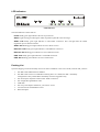
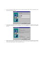
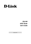
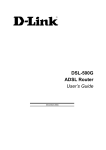
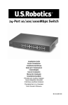
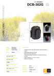
DSL-302G ADSL Ethernet/USB Modem User’s Guide First Edition (February 2002) 6DSL302G..01 Printed In Taiwan Wichtige Sicherheitshinweise 1. Bitte lesen Sie sich diese Hinweise sorgfältig durch. 2. Heben Sie diese Anleitung für den spätern Gebrauch auf. 3. Vor jedem Reinigen ist das Gerät vom Stromnetz zu trennen. Vervenden Sie keine Flüssig- oder Aerosolreiniger. Am besten dient ein angefeuchtetes Tuch zur Reinigung. 4. Um eine Beschädigung des Gerätes zu vermeiden sollten Sie nur Zubehörteile verwenden, die vom Hersteller zugelassen sind. 5. Das Gerät is vor Feuchtigkeit zu schützen. 6. Bei der Aufstellung des Gerätes ist auf sichern Stand zu achten. Ein Kippen oder Fallen könnte Verletzungen hervorrufen. Verwenden Sie nur sichere Standorte und beachten Sie die Aufstellhinweise des Herstellers. 7. Die Belüftungsöffnungen dienen zur Luftzirkulation die das Gerät vor Überhitzung schützt. Sorgen Sie dafür, daß diese Öffnungen nicht abgedeckt werden. 8. Beachten Sie beim Anschluß an das Stromnetz die Anschlußwerte. 9. Die Netzanschlußsteckdose muß aus Gründen der elektrischen Sicherheit einen Schutzleiterkontakt haben. 10. Verlegen Sie die Netzanschlußleitung so, daß niemand darüber fallen kann. Es sollete auch nichts auf der Leitung abgestellt werden. 11. Alle Hinweise und Warnungen die sich am Geräten befinden sind zu beachten. 12. Wird das Gerät über einen längeren Zeitraum nicht benutzt, sollten Sie es vom Stromnetz trennen. Somit wird im Falle einer Überspannung eine Beschädigung vermieden. 13. Durch die Lüftungsöffnungen dürfen niemals Gegenstände oder Flüssigkeiten in das Gerät gelangen. Dies könnte einen Brand bzw. Elektrischen Schlag auslösen. 14. Öffnen Sie niemals das Gerät. Das Gerät darf aus Gründen der elektrischen Sicherheit nur von authorisiertem Servicepersonal geöffnet werden. 15. Wenn folgende Situationen auftreten ist das Gerät vom Stromnetz zu trennen und von einer qualifizierten Servicestelle zu überprüfen: a – Netzkabel oder Netzstecker sint beschädigt. b – Flüssigkeit ist in das Gerät eingedrungen. c – Das Gerät war Feuchtigkeit ausgesetzt. d – Wenn das Gerät nicht der Bedienungsanleitung ensprechend funktioniert oder Sie mit Hilfe dieser Anleitung keine Verbesserung erzielen. e – Das Gerät ist gefallen und/oder das Gehäuse ist beschädigt. f – Wenn das Gerät deutliche Anzeichen eines Defektes aufweist. 16. Bei Reparaturen dürfen nur Orginalersatzteile bzw. den Orginalteilen entsprechende Teile verwendet werden. Der Einsatz von ungeeigneten Ersatzteilen kann eine weitere Beschädigung hervorrufen. 17. Wenden Sie sich mit allen Fragen die Service und Repartur betreffen an Ihren Servicepartner. Somit stellen Sie die Betriebssicherheit des Gerätes sicher. 18. Zum Netzanschluß dieses Gerätes ist eine geprüfte Leitung zu verwenden, Für einen Nennstrom bis 6A und einem Gerätegewicht großer 3kg ist eine Leitung nicht leichter als H05VV-F, 3G, 0.75mm2 einzusetzen i FCC Warning This device complies with part 15 of the FCC Rules. Operation is subject to the following two conditions: (1) This device may not cause harmful interference, and (2) this device must accept any interference received, including interference that may cause undesired operation. This equipment has been tested and found to comply with the limits for a Class B digital device, pursuant to part 15 of the FCC Rules. These limits are designed to provide reasonable protection against harmful interference in a residential installation. This generates, uses and can radiate radio frequency energy and, if not installed and used in accordance with the instructions, may cause harmful interference to radio communications. However, there is no guarantee that interference will not occur in a particular installation. If this equipment does cause harmful interference to radio or television reception, which can be determined by turning equipment off and on, the user is encouraged to try to correct the interference by one or more of the following measures: -Reorient or relocate the receiving antenna. -Increase the separation between the equipment and receiver. -Connect the equipment into an outlet on a circuit different from that to which the receiver is connected. -Consult the dealer or an experienced radio/TV technician for help. CE Mark Warning This is a Class B product. In a domestic environment, this product may cause radio interference in which case the user may be required to take adequate measures. ii TABLE OF CONTENTS ABOUT THIS USER’S GUIDE........................................................................................................................... 3 INTRODUCTION................................................................................................................................................. 1 MODEM DESCRIPTION AND OPERATION .............................................................................................................. 1 MODEM FEATURES.............................................................................................................................................. 1 Front Panel ................................................................................................................................................... 2 Rear Panel..................................................................................................................................................... 2 LED Indicators .............................................................................................................................................. 3 Packing List................................................................................................................................................... 3 HARDWARE INSTALLATION......................................................................................................................... 4 Modem Location ........................................................................................................................................................ 4 Connect the Power...................................................................................................................................................... 4 Connect ADSL Line................................................................................................................................................... 4 Connect Modem to Computer........................................................................................................................ 4 SOFTWARE INSTALLATION .......................................................................................................................... 5 INSTALL THE MODEM CONFIGURATION UTILITY ................................................................................................ 5 CONFIGURE THE MODEM .................................................................................................................................... 9 INSTALL THE USB DRIVER ............................................................................................................................... 11 Installing the PC (Ethernet Client) Driver CONFIGURING THE ETHERNET CLIENT DRIVER.................................................................................................. 15 MODEM DIAGNOSTICS ...................................................................................................................................... 17 Advanced Diagnostics ................................................................................................................................. 18 TECHNICAL SPECIFICATIONS ................................................................................................................... 20 FACTORY RESET............................................................................................................................................. 19 DSL-302G FIRMWARE UPGRADE UTILITY.............................................................................................. 21 DSL-302G ADSL Ethernet Modem User’s Guide About This User’s Guide This user’s guide provides instructions on how to install the DSL-302G ADSL Modem and use it to connect a computer (or two computers) to the Internet. If you are using a computer with a functioning Ethernet port, you can use the Quick Installation Guide to quickly establish your ADSL connection and access the Internet. If you want to use only the USB port for the initial connection you will find instructions for USB operation in the section titled “USB Driver” Terminology This document uses the terms “Modem” (first letter upper case) to refer specifically to the DSL-302G ADSL Modem, and “modem” (first letter lower case) to refer to all such devices including the DSL-302G. ADSL service is provided by different types of businesses including telephone service providers, Internet service providers and other businesses that provide computer network and telecommunications services. The term “service provider” is used in this guide to refer to any service that sells or leases DSL services and equipment. Before You Start Please read and make sure you understand all the prerequisites for proper installation of your new Modem. Have all the necessary information and equipment on hand before beginning the installation. Low Pass Filters ADSL and telephone services share the same copper wire to carry their respective signals, a filtering mechanism may be necessary to avoid mutual interference. It may be necessary to install a low pass filter device (also called micro-filter or splitter) for each telephone that shares the line with the ADSL line. Micro-filters are easy to install passive devices that connect to the ADSL device and/or telephone using standard telephone cable. Ask your service provider for more information about the use of low pass filters with your installation. VPI and VCI Settings For some installations, it will be necessary to configure certain settings used by the Modem for connection to the Internet. If your Modem has not already been configured to the specific requirements of your ADSL account, you will have to change these settings using the Configuration Utility software included with the device. If necessary, your service provider will provide two numbers, a Virtual Path Identifier (VPI) and a Virtual Channel Identifier (VCI) that are needed for proper configuration of the Modem. These numbers are used to manage the service provider’s network infrastructure. 3 Introduction This section provides a brief description of the Modem, its associated technologies and a list of Modem features. What is ADSL? Asymmetric Digital Subscriber Line (ADSL) is an access technology that utilizes ordinary copper telephone lines to enable broadband high-speed digital data transmission and interactive multimedia applications for business and residential customers. For ADSL services, it is not necessary expensive new cabling or condition the line in any way. ADSL greatly increases the signal carrying capacity of copper telephone lines without interfering with regular telephone services. For the ADSL user, this means faster downloads and more reliable connectivity. ADSL devices make it possible to enjoy benefits such as high-speed Internet access without experiencing any loss of quality or disruption of voice/fax telephone capabilities. ADSL provides a dedicated service over a single telephone line operating at speeds of up to 8 Mbps downstream and up to 640 Kbps upstream, depending on local telephone line conditions. A secure point-to-point connection is established between the user and the central office of the service provider. D-Link ADSL devices incorporate the recommendations of the ADSL Forum regarding framing, data format, and upper layer protocols. Modem Description and Operation The DSL-302G ADSL Ethernet Modem is easy to install and use. You can use the Modem to connect one computer using its Ethernet interface, and another computer using the USB interface. The Modem can be managed through either interface. Once the Modem has been set up, the Ethernet port can be used by any Ethernet enabled computer to connect to the Internet. To use the USB port, a special device driver must be installed on any computer connecting to the Modem through the USB interface. Modem Features The DSL-302G ADSL Ethernet Modem utilizes the latest ADSL enhancements and technologies to provide a reliable Internet portal suitable for most small to medium sized offices. • Flexible Connectivity Choose either the USB port or the Fast Ethernet port to connect • Multiple User Support Both port can be used simultaneously to connect two computers • Plug and Play USB Installation The USB driver installs automatically • Bridged Ethernet over ATM Support The DSL-302G supports RFC 1483 • Installation Wizard The easy-to-use configuration utility connects you quickly • Auto-detect Function The device complies with the most common standards used for ADSL connection and automatically selects the correct connection type during the initialization process • MIB Support Built-in MIBs allow SNMP management functions Front Panel Place the Modem in a location that allows a view of the LED indicators. To save space you can use the feet to stand the device on either its right or left side. Front Panel Rear Panel All cable connections to the Modem are made at the rear panel. The factory reset button is located here as well. Rear Panel LED Indicators LED Indicators The LED Indicators read as follows: Power Steady green light indicates the unit is powered on. Status Lights steady green during the ADSL negotiation phase & connection stage. ADSL: Link Steady green light indicates a valid ADSL connection. This will light after the ADSL negotiation process has been settled. ADSL: Act Blinking green light indicates an active WAN session. Ethernet: Link Steady green light indicates a valid Ethernet connection. Ethernet: Act Blinking green indicates an active Ethernet session. USB: Link Steady green light indicates a valid USB connection. USB: Act Blinking green indicates an active USB session. Packing List Open the shipping carton and carefully remove all items. In addition to this User's Guide, ascertain that you have: 1. 2. 3. 4. 5. 6. 7. 8. One DSL-302G ADSL Ethernet Modem One DSL-302G tool kit on CD-ROM containing The User’s Guide, the DSL- 300 Family Configuration Utility and the DSL-300 Family Firmware Upgrade Utility One twisted-pair telephone cable used for ADSL connection One straight-through Ethernet cable USB cable One AC power adapter suitable for your electric service Two feet used to stand Modem on end DSL-302G QIG Hardware Installation This chapter describes the various network cable and power connections required to use the Modem. Modem Location When selecting the location for the Modem be sure to allow room to access the connections on the rear panel. You will want to place the Modem so that you will be able to see the LED indicators on the front panel. Allow some space above the Modem for ventilation to avoid problems with overheating. The Modem package includes two feet that can be used to stand the unit on one side if you wish to save space. Connect the Power Insert the AC Power Adapter cord into the power receptacle located on the rear panel of the Modem and plug the adapter into a nearby power source. You should see the Power LED indicator light up and remain lit. Connect ADSL Line You can use the twisted-pair telephone ADSL cable included with the Modem to connect to your telephone line. Simply plug one end of the cable into the ADSL port (RJ-11 receptacle) on the rear panel of the Modem, and insert the other end into the telephone wall socket or low pass filter, as instructed by your service provider. Connect Modem to Computer The Modem may be connected to any Ethernet-ready computer or any computer with a USB port. An Ethernetready computer includes any PC or notebook computer with a working 10Mbps or 100Mbps Ethernet port. Connect to the Ethernet port with a straight-through Ethernet cable (included). The RJ-45 Ethernet port is an MDI-X (crossed) port, and can be connected to an MDI-II (straight-through) port, such as an Ethernet port on a computer, with a straight-through cable. Connecting an MDI-X port to another MDI-X port requires either a cross-wired cable or a straight-through cable used with a cross-wired adapter. The rules governing Ethernet cable lengths apply to the computer-to-Modem connection. Be sure that the cable connecting the computer to the Modem does not exceed 100 meters. Any computer using the USB port to connect to the Modem requires additional drivers specific to the Modem. See the instructions in the section titled USB Drivers. Connect the Modem to a PC or notebook computer as shown in the example below: To Power Source USB Cable Ethernet Cable ADSL Line Software Installation In order to install the software driver for the Modem, you first need to install the DSL-300 Configuration Utility, D-Link’s GUI based management software. This software can later be used to monitor the device or change its settings. Install the Configuration Utility software on the PC directly connected to the device via either the Ethernet or USB interface. In order to install the Configuration Utility on a computer using the USB interface, two additional drivers must be installed. A special USB driver and an Ethernet client driver must first be installed on the computer. It is then necessary to configure the Ethernet client driver. Read the instructions in the section titled USB Driver if you are configuring the Modem using the USB interface. Install the Modem Configuration Utility Install the Configuration Utility software by inserting the setup CD-ROM disc into your CD-ROM drive and wait for the following screen prompts to appear: 1. The Setup window informs you that it is preparing the “InstallShield Wizard”. 2. The Welcome window recommends exiting all other programs before starting the setup procedure. If you do not wish to close other programs click Cancel, otherwise quit all other programs and click Next. 3. The User Information window asks you for your name and company name. Enter this information in the appropriate field and click Next. 4. In the Choose Destination Location window you may accept to install the Configuration Utility in the automatically chosen directory by clicking Next. Or you can click Browse if you wish to select a different directory. 5. The Select Program Folder window asks you to select a different folder or you can rename the D-Link DSL Family folder that has been created for the program icon. You can rename the folder by typing in a new name in the “Program Folder:” field. Click Next to continue. 6. The Start Copying Files window provides an opportunity to review the information you have just entered. If you are satisfied with the information as it is listed, click Next. If you need to change any of the information click Back to go to the previous window(s) to make the changes. 7. In the Setup Complete window you are presented with the option to launch the Configuration Utility program. If you wish to start the program now, click in the vacant box next to the “Yes, Launch the program file” option. A check mark (√) should appear in the box indicating it has been selected. Click Finish to launch the Configuration Utility. A Configuration Utility icon should now be seen on your desktop screen. Configure the Modem With the Configuration Utility software installed, you are ready to configure the Modem. You must enter the VPI and VCI values that have been given to you by your ADSL service provider to define the path of connection to the ATM network backbone. Click the Configuration Utility icon to initiate the configuration of the Modem. The Configuration Utility will locate the Modem on your LAN. 1. If the DSL-302G and corresponding MAC address does not appear in the Device List of the Configuration Utility window, click the Discover button on the bottom of the window. The DSL-302G should appear in the Device Name column preceded by the MAC Address of the device. If there are other DSL-300 Family Modems on the same network, these may also appear in the list. 2. Double-click on the Modem in the list or highlight it and depress the Enter key. The main menu appears, click on the General ADSL Information tab to configure the Modem. 3. In the new window you must enter the VPI and VCI numbers (assigned to you by your service provider). Type in these numbers in the ADSL Setting field and click Finish. 4. The Save configuration and restart system window will appear. You will be asked if you would like to save the changes you have made (the VPI and VCI numbers) and restart the Modem. Click Yes if you have correctly entered the necessary information. 5. The final window, Configuration saved, confirms that you have made changes to the configuration of the Modem and restarted it. If you wish to close the Configuration Utility, click Yes. Install the USB Driver To install the USB driver for a computer-attached configuration with a computer running a Windows operating system, follow the procedure below. 1. Plug the USB connector to the DSL-302G, then the Add New Hardware Wizard dialog box is displayed showing the type of USB device that has booted up: 2. Click on Next to continue. The following dialog box is displayed asking you to specify how to install the driver: 3. Ensure that the first option is selected and click on Next. The following dialog box is displayed asking you to specify where the driver can be found: 4. Insert the PC Driver install disk. 5. Check the Floppy disk drive option and click on Next. The following dialog box is displayed which confirms that a suitable driver has been found on the floppy disk which will now be installed: 6. Click on Next to begin the installation of the driver. When the installation has finished, the following dialog box is displayed: 7. Click on the Finish button to complete the installation. The PC Driver for the USB device is now installed. Installing the PC (Ethernet Client) Driver To install the PC (Ethernet Client) driver for a PC-attached configuration on a PC running Windows 98 SE/Windows 2000, follow the procedure below: Note: If you have just installed the PC (USB) driver for a PC-attached Modem configuration, this procedure will automatically follow on from either of these procedures. The PC having initially detected the DSL-302G as a PC-attached USB device will now detect the DSL-302G as an Ethernet device. Therefore, the Ethernet driver (VVB Client) now needs to be installed. If this procedure does not automatically follow, you need to reset your DSL-302G. 1. The Add New Hardware Wizard dialog box is displayed showing that it needs to install a driver for the VVB Ethernet port: 2. Click on Next to continue. The following dialog box is displayed asking you to specify how to install the driver: 3. Ensure that the first option is selected and click on Next. The following dialog box is displayed asking you to specify where the driver can be found: 4. Insert the PC Driver install disk. 5. Check the Floppy disk drive option and click on Next. The following dialog box is displayed which confirms that a suitable driver has been found on the floppy disk which will now be installed: 6. Click on Next to begin the installation of the driver. 7. You may be asked to insert the Windows installation CD-ROM that was supplied with your PC. If so, insert the CD and click on Next. When the installation has finished, the following dialog box is displayed: 8. Click on the Finish button to complete the installation. The PC driver for the VVB Ethernet port is now installed. 9. You will be asked to restart your computer. Click on Yes to restart the computer. After the reboot, the PC Driver for the Ethernet port will be fully installed. Refer to the next section to configure the driver. Configure the Ethernet Client Driver To configure the Ethernet Client driver, follow the procedure below: 1. Choose Settings > Network and Dial-up Connections from the Start menu. 2. The Network and Dial-up Connections window is displayed. 3. Right-click on the Local Area connection icon in this window and choose Properties from the menu displayed. The Local Area Connection Properties dialog box is displayed: 4. Click on the Internet Protocol item in the list box. 5. Click on the Properties button. The Internet Protocol (TCP/IP) Properties window is displayed: 6. Enter the details of the DSL-302G in the Use the following IP address group box: IP address Subnet mask Default gateway 7. Click on OK. 8. Click on OK again to close the remaining open dialog box. The Ethernet Client driver has now been configured. It is advisable to check that the Ethernet driver has been configured correctly by pinging the IP address of the DSL-302G from a Command Prompt window. Modem Diagnostics The Configuration Utility can be used to monitor the activity and performance of the Modem. The four status windows are read-only with the exception of the General ADSL Information. Once you have set the VCI and VPI values there should not be any need to change them. You can choose the interval in which the statistics are refreshed from the pull-down menu on the bottom of the window. Clicking on the ADSL Status tab provides information about the status of the ADSL link and the data. In this window you can view the following information: ♦ Link Status – current status of the ADSL link ♦ Protocol – ADSL protocol used to provide the connection ♦ Data Path – Fast or Interleave mode (depending on the DSLAM) ♦ Upstream - Displays upstream data bit rate in Kbps ♦ Downstream - Displays downstream data bit rate in Kbps The lighted indicator indicates the connection status by its color. ♦ Red light – not connected ♦ Yellow/Black flashing light – connecting ♦ Green light - connected The General ADSL Information menu displays information on packets received and transmitted via the ADSL line as well as the ADSL settings. This is where you can change the VCI and VPI values, as described in the previous section. The Ethernet Information menu provides information about packets received and transmitted via the Ethernet interface. The Version Information menu lists the current device driver, firmware version and hardware version. Advanced Diagnostics To view the advanced diagnostics menus available with the configuration utitilty depress CTRL + V while the utility is displayed. The Advanced ADSL Information menu lists information about errors, signal characteristics and loop distance. The data provided in the Advanced ADSL Information window includes: ♦ Re_training – number of attempts to establish the ADSL connection ♦ CRC – Cyclic Redundancy Checking, number of CRC errors since ADSL connection established ♦ FEC – Forward Error Correction, number of FEC errors since ADSL connection established ♦ HEC – Header Error Checking, number of HEC errors since ADSL connection established ♦ Line Attenuation – measured in dB ♦ Noise Margin – measured in dB ♦ Output Power – measured in dBm The Carrier Information menu displays the frequency distribution of the upstream and downstream bandwidth. The upstream portion occupies the lower frequency block. Factory Reset The Modem can be reset to the factory default settings using the reset button located on the rear panel. To reset the Modem, gently depress the reset button with a paper clip while the unit is powered on. A Technical Specifications General Standards: ITU G.992.1 (G.dmt) ITU G.992.2 (G.lite) ITU G.994.1 (G.Hs) ANSI T1.413 (Issue 2) Protocol: TCP/IP Data Transfer Rate: G.dmt full rate: Downstream up to 8 Mbps Upstream up to 640 Kbps G.lite: Downstream up to 1.5 Mbps Upstream up to 512 Kbps Media Interface Exchange: RJ-11 port ADSL telephone line connection RJ-45 port for 10BASET Ethernet connection Physical and Environmental DC inputs: Input: 120V AC 60Hz 24W Power Adapter: Output: 9V AC 1000 mA Power Consumption: 10 Watts (Max) Operating Temperature: 0° to 50° C (32° - 122° F) Humidity: 5 to 95% (non-condensing) Dimensions: 223.3mm x 131.7mm x 35mm Weight: 455gm (1 lb.) EMI: FCC Class B, CE Class B Safety: CSA International B DSL-302G Firmware Upgrade Utility You can update system firmware using the DSL-302G Firmware Upgrade Utility. To upgrade the Modem’s firmware you must have installed this software on the PC you wish to use for this purpose. Install the utility by clicking the self-executing file setup.exe located on the Installation CD-ROM. It will be installed automatically. It is recommended that the PC be directly connected to the Modem using a crossed cable, however you may upgrade it through the LAN from a remote host. You also need to download the latest firmware version file from the D-Link web site to the PC on which you will use the Upgrade Utility. Instructions for downloading the firmware are located on the web site at www.dlink.com. To launch the DSL-302G Firmware Upgrade Utility, click on the icon. Allow a few moments for the software to discover the Modem on the network. After the discovery phase the following window will appear. You will see any DSL-302G Modems on your network. You can identify individual devices by either its IP address or its MAC address. Select the device you wish to upgrade by double clicking on it. In the new window, you will see the MAC address of the Modem and the IP address of the PC you are using. The PC and the Modem must be on the same subnet for the upgrade to be completed. The upgrade utility will suggest a new IP address to be temporarily assigned to the device during the firmware upgrade procedure. Check the suggested IP address listed for the Modem to be sure that it does not conflict with any existing IP addresses on your network. To change the temporary IP address of the Modem, type in an available IP address in the space provided. You should change only the host portion of the address. To upload the new firmware to the selected Modem click the ‘Upgrade’ button. The utility will automatically load the new firmware. During the upgrade process it is important that you allow the entire file to load onto the device. Do not turn off the Modem while the flash memory is being updated. A warning will appear during the upgrade reminding you not to power off the device. When the new firmware has been successfully loaded a new window will inform you of the upgrade and tell you that the Modem has been restarted. Click OK to proceed. D-Link Systems, Inc. (“D-Link”) provides this limited warranty for its product only to the person or entity who originally purchased the product from D-Link or its authorized reseller or distributor. Limited Hardware Warranty: D-Link warrants that the hardware portion of the D-Link products described below (“Hardware”) will be free from material defects in workmanship and materials from the date of original retail purchase of the Hardware, for the period set forth below applicable to the product type (“Warranty Period”) if the Hardware is used and serviced in accordance with applicable documentation; provided that a completed Registration Card is returned to an Authorized D-Link Service Office within ninety (90) days after the date of original retail purchase of the Hardware. If a completed Registration Card is not received by an authorized D-Link Service Office within such ninety (90) day period, then the Warranty Period shall be ninety (90) days from the date of purchase. Product Type Warranty Period Product (including any power supplies and fans), if purchased and delivered in the fifty (50) United States, or the District of Columbia (“USA”) 1-Year Spare parts and spare kits Ninety (90) days Limited Warranty D-Link’s sole obligation shall be to repair or replace the defective Hardware at no charge to the original owner. Such repair or replacement will be rendered by D-Link at an Authorized D-Link Service Office. The replacement Hardware need not be new or of an identical make, model or part; D-Link may in its discretion may replace the defective Hardware (or any part thereof) with any reconditioned product that D-Link reasonably determines is substantially equivalent (or superior) in all material respects to the defective Hardware. The Warranty Period shall extend for an additional ninety (90) days after any repaired or replaced Hardware is delivered. If a material defect is incapable of correction, or if D-Link determines in its sole discretion that it is not practical to repair or replace the defective Hardware, the price paid by the original purchaser for the defective Hardware will be refunded by D-Link upon return to D-Link of the defective Hardware. All Hardware (or part thereof) that is replaced by D-Link, or for which the purchase price is refunded, shall become the property of D-Link upon replacement or refund. Limited Software Warranty: D-Link warrants that the software portion of the product (“Software”) will substantially conform to D-Link’s then current functional specifications for the Software, as set forth in the applicable documentation, from the date of original delivery of the Software for a period of ninety (90) days (“Warranty Period”), if the Software is properly installed on approved hardware and operated as contemplated in its documentation. D-Link further warrants that, during the Warranty Period, the magnetic media on which D-Link delivers the Software will be free of physical defects. D-Link’s sole obligation shall be to replace the non-conforming Software (or defective media) with software that substantially conforms to D-Link’s functional specifications for the Software. Except as otherwise agreed by D-Link in writing, the replacement Software is provided only to the original licensee, and is subject to the terms and conditions of the license granted by D-Link for the Software. The Warranty Period shall extend for an additional ninety (90) days after any replacement Software is delivered. If a material non-conformance is incapable of correction, or if D-Link determines in its sole discretion that it is not practical to replace the non-conforming Software, the price paid by the original licensee for the non-conforming Software will be refunded by D-Link; provided that the non-conforming Software (and all copies thereof) is first returned to D-Link. The license granted respecting any Software for which a refund is given automatically terminates. What You Must Do For Warranty Service: Registration Card. The Registration Card provided at the back of this manual must be completed and returned to an Authorized D-Link Service Office for each D-Link product within ninety (90) days after the product is purchased and/or licensed. The addresses/telephone/fax list of the nearest Authorized D-Link Service Office is provided in the back of this manual. FAILURE TO PROPERLY COMPLETE AND TIMELY RETURN THE REGISTRATION CARD MAY AFFECT THE WARRANTY FOR THIS PRODUCT. Submitting A Claim. Any claim under this limited warranty must be submitted in writing before the end of the Warranty Period to an Authorized D-Link Service Office. The claim must include a written description of the Hardware defect or Software nonconformance in sufficient detail to allow D-Link to confirm the same. The original product owner must obtain a Return Material Authorization (RMA) number from the Authorized D-Link Service Office and, if requested, provide written proof of purchase of the product (such as a copy of the dated purchase invoice for the product) before the warranty service is provided. After an RMA number is issued, the defective product must be packaged securely in the original or other suitable shipping package to ensure that it will not be damaged in transit, and the RMA number must be prominently marked on the outside of the package. The packaged product shall be insured and shipped to D-Link, 53 Discovery Drive, Irvine CA 92618, with all shipping costs prepaid. D-Link may reject or return any product that is not packaged and shipped in strict compliance with the foregoing requirements, or for which an RMA number is not visible from the outside of the package. The product owner agrees to pay D-Link’s reasonable handling and return shipping charges for any product that is not packaged and shipped in accordance with the foregoing requirements, or that is determined by D-Link not to be defective or non-conforming. What Is Not Covered: This limited warranty provided by D-Link does not cover: Products that have been subjected to abuse, accident, alteration, modification, tampering, negligence, misuse, faulty installation, lack of reasonable care, repair or service in any way that is not contemplated in the documentation for the product, or if the model or serial number has been altered, tampered with, defaced or removed; Initial installation, installation and removal of the product for repair, and shipping costs; Operational adjustments covered in the operating manual for the product, and normal maintenance; Damage that occurs in shipment, due to act of God, failures due to power surge, and cosmetic damage; and Any hardware, software, firmware or other products or services provided by anyone other than D-Link. Disclaimer of Other Warranties: EXCEPT FOR THE LIMITED WARRANTY SPECIFIED HEREIN, THE PRODUCT IS PROVIDED “AS-IS” WITHOUT ANY WARRANTY OF ANY KIND INCLUDING, WITHOUT LIMITATION, ANY WARRANTY OF MERCHANTABILITY, FITNESS FOR A PARTICULAR PURPOSE AND NON-INFRINGEMENT. IF ANY IMPLIED WARRANTY CANNOT BE DISCLAIMED IN ANY TERRITORY WHERE A PRODUCT IS SOLD, THE DURATION OF SUCH IMPLIED WARRANTY SHALL BE LIMITED TO NINETY (90) DAYS. EXCEPT AS EXPRESSLY COVERED UNDER THE LIMITED WARRANTY PROVIDED HEREIN, THE ENTIRE RISK AS TO THE QUALITY, SELECTION AND PERFORMANCE OF THE PRODUCT IS WITH THE PURCHASER OF THE PRODUCT. Limitation of Liability: TO THE MAXIMUM EXTENT PERMITTED BY LAW, D-LINK IS NOT LIABLE UNDER ANY CONTRACT, NEGLIGENCE, STRICT LIABILITY OR OTHER LEGAL OR EQUITABLE THEORY FOR ANY LOSS OF USE OF THE PRODUCT, INCONVENIENCE OR DAMAGES OF ANY CHARACTER, WHETHER DIRECT, SPECIAL, INCIDENTAL OR CONSEQUENTIAL (INCLUDING, BUT NOT LIMITED TO, DAMAGES FOR LOSS OF GOODWILL, WORK STOPPAGE, COMPUTER FAILURE OR MALFUNCTION, LOSS OF INFORMATION OR DATA CONTAINED IN, STORED ON, OR INTEGRATED WITH ANY PRODUCT RETURNED TO D-LINK FOR WARRANTY SERVICE) RESULTING FROM THE USE OF THE PRODUCT, RELATING TO WARRANTY SERVICE, OR ARISING OUT OF ANY BREACH OF THIS LIMITED WARRANTY, EVEN IF D-LINK HAS BEEN ADVISED OF THE POSSIBILITY OF SUCH DAMAGES. THE SOLE REMEDY FOR A BREACH OF THE FOREGOING LIMITED WARRANTY IS REPAIR, REPLACEMENT OR REFUND OF THE DEFECTIVE OR NON-CONFORMING PRODUCT. GOVERNING LAW: This Limited Warranty shall be governed by the laws of the state of California. Some states do not allow exclusion or limitation of incidental or consequential damages, or limitations on how long an implied warranty lasts, so the foregoing limitations and exclusions may not apply. This limited warranty provides specific legal rights and the product owner may also have other rights which vary from state to state. Trademarks: Copyright 2001 D-Link Corporation. Contents subject to change without prior notice. D-Link is a registered trademark of DLink Corporation/D-Link Systems, Inc. All other trademarks belong to their respective proprietors. Copyright Statement: No part of this publication may be reproduced in any form or by any means or used to make any derivative such as translation, transformation, or adaptation without permission from D-Link Corporation/D-Link Systems Inc., as stipulated by the U.S. Copyright Act of 1976. CE Mark Warning: This is a Class B product. In a domestic environment, this product may cause radio interference, in which case the user may be required to take adequate measures FCC Warning: This device complies with part 15 of the FCC Rules. Operation is subject to the following two conditions: (1) This device may not cause harmful interference, and (2) this device must accept any interference received, including interference that may cause undesired operation. This equipment has been tested and found to comply with the limits for a Class B digital device, pursuant to part 15 of the FCC Rules. These limits are designed to provide reasonable protection against harmful interference in a residential installation. This generates, uses and can radiate radio frequency energy and, if not installed and used in accordance with the instructions, may cause harmful interference to radio communications. However, there is no guarantee that interference will not occur in a particular installation. If this equipment does cause harmful interference to radio or television reception, which can be determined by turning equipment off and on, the user is encouraged to try to correct the interference by one or more of the following measures: -Reorient or relocate the receiving antenna. -Increase the separation between the equipment and receiver. -Connect the equipment into an outlet on a circuit different from that to which the receiver is connected. -Consult the dealer or an experienced radio/TV technician for help. To Register Your D-Link Product, register online at http://www.dlink.com/sales/reg