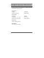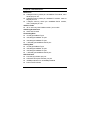
1
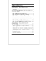
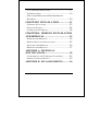
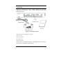
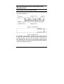
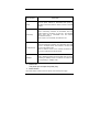
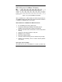
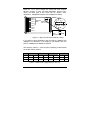
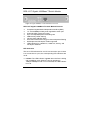
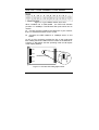
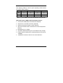
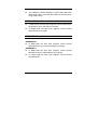
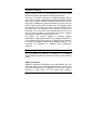
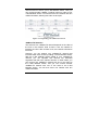
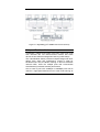
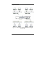
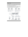
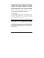
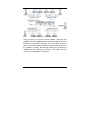
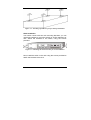
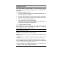
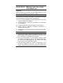
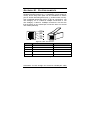
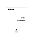
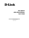
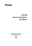
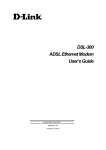
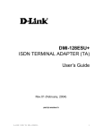
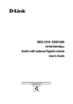
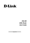
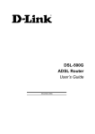
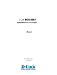
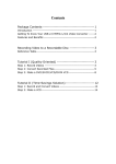
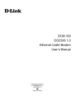
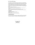
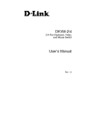
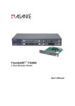
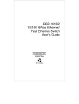
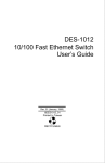
DES-1200M Fast Ethernet Switch System User’s Guide Rev. 03 (MAR. 2001) 6012-9830016 Printed In Taiwan RECYCLABLE TABLE OF C ONTENTS TABLE OF CONTENTS ..................................II CHAPTER 1 INTRODUCTION .................. 1 UNPACKING ........................................................... 3 DEVICE DESCRIPTION, FEATURES AND CAPABILITIES ................................................. 4 DES-1200M FRONT AND REAR PANELS ...................... 4 DES-128 8 PORTS 10/100BASE-TX MODULE............... 6 DES-121T GIGABIT 1000BASE-T SWITCH MODULE ..... 8 FD THE LED INDICATOR IS YELLOW WHEN THE PORT IS OPERATING IN FULL-DUPLEX MODE. WHEN THE PORT IS OPERATING IN HALF- ..................... 9 DES-124F 4 PORTS 100BASE-FX FIBER MODULE ...... 10 DES-121G/GL 1000BASE-SX/LX FIBER MODULE ..... 12 DUPLEX MODE, THE LED INDICATOR IS NOT LIT. CHAPTER 2 PLANNING YOUR NETWORK ..................................................... 13 10BASE-T ETHERNET NETWORK GUIDELINES ............ 13 100BASE-TX FAST ETHERNET NETWORK GUIDELINES 13 100BASE-FX FAST ETHERNET NETWORK GUIDELINES 14 1000BASE-SX AND LX NETWORK GUIDELINE .......... 14 NETWORK PLANNING ............................................. 15 EXPANDED NETWORKS .......................................... 15 ii COLLAPSED BACKBONE LINK .................................. 17 FILESERVER LINK .................................................. 19 MULTI-PORT BRIDGE WITH HIGH-BANDWIDTH BACKBONE .......................................................... 20 CHAPTER 3 INSTALLATION .................. 22 CHOOSING A LOCATION ......................................... 22 SUPPLYING POWER ................................................ 24 CONNECTING THE SWITCH ...................................... 24 CHAPTER 4. MODULE INSTALLATION AND REMOVAL ........................................... 25 HANDLING THE MODULES....................................... 25 MODULE SETUP AND INSTALLATION ......................... 25 INSTALLING THE MODULES ..................................... 26 REMOVING THE MODULES ...................................... 27 APPENDIX A. TECHNICAL SPECIFICATIONS .......................................... 28 COMPATIBILITY WITH ETHERNET STANDARDS: ........... 28 PHYSICAL CHARACTERISTICS: ................................. 29 APPENDIX B. PIN ASSIGNMENTS............ 30 iii C HAPTER 1 I NTRODUCTION DES-1200M are multi-speed network devices combining Ethernet, Fast Ethernet and Gigabit Ethernet capabilities in a single compact, rack-mountable cabinet. Combining 10Mbps Ethernet, 100Mbps Fast Ethernet and Gigabit Ethernet interfaces in one unit allows these switches to unclog existing LANs and provide a path to efficient, high-speed networking. DES-1200M is a combination of a 4-slot host cabinet which accepts more than 15 different media modules. A maximum configuration of 32 x 10/100Base-TX switched ports can be achieved using 4 X 8 port 10/100Base-TX modules. In the same way, a maximum configuration of 32×10/100Base-TX or 8/16/32 ×100Base-FX ports, or 4 x 1000Base-SX/LX can be accommodated in the host cabling. Any of the above modules can be integrated to give up to many different configurations. 1 Unpacking Open the shipping cartons of DES-1200M and carefully unpacks its contents. The carton should contain the following items: Figure 1-1. Package Contents DES-1200M 4-Slot Fast Ethernet System AC power cord Rack mounting kit Four Rubber feet This User’s Guide If any item is found missing or damaged, please contact your local reseller for replacement. 3 D EVICE D ESCRIPTION , F EATURES C APABILITIES AND DES-1200M Front and Rear Panels This section describes the features on the front and rear panels of the DES-1200M unit. Figure 1-2. Front Panel Figure 1-3. Rear Panel All LED status indicators are located on the FRONT panel of the switches. They provide a real-time indication of system and operational status. The ports for connections to other devices and networks are also on the front panels, along with the crossover switches. The following sections provide descriptions of the LED indicators and ports. 4 LED Indicators Explanation Power The red power indicator is illuminated when power is provided to the switch and the switch is turned in the ON position. Link/Activity Green Link/Activity indicators are illuminated when the switch detects a connection to that port. The indicator blinks when data is transmitted over the network connected to that port. When a port is not connected, the indicator is off. Full Duplex/Col Red Full Duplex/Col indicators are illuminated when that port is in full duplex mode. The indicator is off when that port is in half duplex mode. When a collision occurs on the network connected to a port, that Full Duplex/Col indicator blinks. 100Mbps Green 100Mbps indicators are illuminated when the port is operating in 100Mbps mode. The indicator is off when the port is operating in 10Mbps mode. Power Port The power port accepts the power plug. Power Switch The power switch, located on the rear panel, controls the power supply 5 DES-128 8 ports 10/100Base-TX Module Figure 1-4. 8 port 10/100Base-TX Module When installed into a DES-1200M, the DES-128 provides 8x 10/100Mbps Switch ports which can connect the DES-1200M to a 10Mbps or 100Mbps hub or end station. DES-128 8 Ports 10/100Base-TX Module Features 8x 10/100Base-TX N-Way Switch ports. Conforms to IEEE 802.3 10Base-T and IEEE 802.3u 100Base-TX and IEEE 802.3x Ethernet Standards Store and forward switch architecture for abnormal packet filtering Support for half and full duplex on all ports Backplane up to 2.4Gbps 5M memory Buffer support Automatic address learning with 4K address entry storage Filtering and forwarding rate of 14,880~148,800 packets per second DIP Switch with Link Mode The DES-128 8 port 10/100Base-TX module provides dip 6 switch for 1 to 4 port to adjust link mode with other network devices. Another 4 ports use auto-negotiation protocol only. There are three type of link mode can be chosen, Autonegotiation, 100Mbps/Full duplex and 10Mbps/Full duplex. Port 1 Port 2 Port 3 ON adjustable DIP Sw itch for ports Port 1 to Port 4 Port 4 Port 1 Port 3 1 2 3 4 5 6 7 8 Port 5 Port 2 Port 6 Port 4 OFF Port 7 Full Duplex Port 8 10M Auto1 2 100M negotiation Figure 1-5. Dip switch location and mode settings If you adjust to auto-negotiation, then the DIP for 100Mbps and 10Mbps is not effective. If you adjust to Full duplex, then the DIP for 100Mbps and 10Mbps is effective. The following Table 1-1. lists the ports’ operating modes based on the DIP switch position. SW ON OFF PORT 1 PORT 2 1 2 3 4 Full 10M Full 10M Auto 100M Auto 100M PORT3 5 6 Full 10M Auto 100M PORT4 7 8 Full 10M Auto 100M Table 1-1. DIP switch configuration for Port 1-4. 7 DES-121T Gigabit 1000Base-T Switch Module Figure 3. Gigabit 1000Base-T Switch Module Front View DES-121T Gigabit 1000Base-T Switch Module Features Compliant Gigabit Media Independent Interface (GMII ) 1 X 100/1000Mbps N-Way auto-negotiation switch port Automatic MDI crossover function Up to 2.4Gbps Backplane forwarding rate 3MB memory buffer sharing 4K-entry Mac Address Table Store-and-forward technology for abnormal packet filtering Half-duplex and full-duplex modes supported LED-indicators for 1000M Link, 100M Link, Activity, and Full-duplex statuses LED Indicators The are 4 LED indicators for one RJ-45 connection port. If there is no connection to a port, the corresponding LED indicators are not lit. LK1000 The LED indicator is green when the Port is linking with 1000Mbps mode. When the port is operating in 10Mbps/100Mbps mode or not connected, the LED indicator is not lit. 8 ACT This LED indicator blinks green when the port is transmitting or receiving packets. When the device is not attached, the LED indicator is not lit. LK100 The LED indicator is green when the Port is linking with 100Mbps mode. When the port is operating in 10Mbps mode or not connected, the LED indicator is not lit. FD The LED indicator is yellow when the port is operating in Full-duplex mode. When the port is operating in Halfduplex mode, the LED indicator is not lit. 9 DES-124F 4 Ports 100Base-FX Fiber Module Figure 1-8. 4 port 100Base-TX/FX Front View When installed into a DES-1200M , the DES-124F Module provides 4 x 100Mbps Fast Ethernet fiber ports which can be used to: Connect the DES-1200M to the backbone of your network; that is, to a basement switch, hub or router. Connector the DES-1200M to a 100Mbps server or end station. An ST (or SC) connector provides the link to the multi-mode fiber cabling and three LEDs show five status of the Module ata glance. A DIP-switch sets the operating mode to half duplex or full duplex (default). Port 1 Port 2 10 Half Duplex Figure 1-9. Location and setting duplex mode ON Full Duplex Port 4 1 2 3 4 DIP Sw itch Location OFF Port 3 The following Table1-3. lists the ports operating modes based on the DIP switch position. PORT 1 PORT 2 PORT3 PORT4 SW 1 2 3 4 ON Half-Duplex Half-Duplex Half-Duplex Half-Duplex OFF Full-Duplex Full-Duplex Full-Duplex Full-Duplex Table 1-3. 4 ports 100Base-FX Fiber Module DIP switch functions DES-124F 4 ports 100Base-FX Fiber Module Feature Conforms to IEEE 802.3u Fast Ethernet standard Support SC or ST fiber connector (optional) Support half and full duplex via DIP switches Store-and-forward switch architecture for abnormal packets filtering Backplane up to 2.4Gbps Automatic address learning with 12K address entry storage Filtering and forwarding rate 148,800 packets per second for 100Mbps 100Base-FX uses 62.5/125 micron multi-mode fiber 11 DES-121G/GL 1000Base-SX/LX Fiber Module Figure 1-10. 1000Base-SX/LX Front View When installed into a DES-1200M, the DES-121G/GL 1000Base-SX/LX Module provides 1 Gigabit Ethernet ports which can connect the DES-1200M to a Gigabit Backbone Switch or Server with Gigabit NIC. DES-121G/GL 1000Base-SX/LX Fiber Module Features Conforms to IEEE 802.3z draft 4.2 and 802.3x standard 1x1000Base-SX/LX Ethernet Port 3M memory buffer support Standard auto-negotiation for speed, duplex mode and flow-control for MII and GMII PHYs Backpressure option and Limit4 option for half duplex Automatic address learning with 4K address entry storage 12 C HAPTER 2 P LANNING YOUR N ETWORK Before you install your DES-1200M, you should review the guidelines for setting up Ethernet networks. Further, you should plan your network to take maximum advantage of its switching capabilities. 10Base-T Ethernet Network Guidelines The maximum length of a 10Base-T cable segment is 100 meters (328 feet). The maximum number of nodes on a 10Base-T segment is one (1) for regular 10Base-T. The recommended cable type is EIA/TIA Category 3 or higher. The maximum network diameter is 500 meters (1,640 feet) for Ethernet networks. The maximum number of segments between any two nodes in the network is five. The maximum number of hubs or repeaters between any two nodes in the network is four. 100Base-TX Fast Ethernet Network Guidelines The maximum length of a 100Base-TX cable segment is 100 meters (328 feet). The maximum number of hubs on a 100Base-TX segment is one if using Class I hubs and two if using Class II hubs. The recommended cable type is EIA/TIA Category 5 untwisted-pair. 13 The maximum network diameter is 200 meters (656 feet) when using Class I hubs and 205 meters (672.5 feet) when using Class II hubs. 100Base-FX Fast Ethernet Network Guidelines In Multi-mode, the fiber optic segment cannot exceed 2 km (62.5/125µm), 2 km (50/125µm) in length. In Single-mode, the fiber optic segment cannot exceed 60km (9/125µm) in length. 1000BASE-SX and LX Network Guideline 1000BASE-SX In Multi-mode, the fiber optic segment cannot exceed 220m (62.5/125µm) or 500m (50/125µm) in length. 1000BASE-LX In Multi-mode, the fiber optic segment cannot exceed 550m(62.5/125µm), 550m(50/125µm) in length. In single mode the fiber optic segment cannot exceed 10km(9/125µm). 14 Network Planning Using a switch, such as a 4-Slot Modular Switch, can expand network topologies and enhance network performance. Each port on a switch connects to a separate network with its own collision domain. Separating networks with these switches allows you to expand 10Base-T networks past the four-hub limit and expand 100Base-TX networks past the one or two hub limit. These switches also filter incoming traffic. On standard hubs and repeaters, any data received on a port is forwarded to all of the other ports. On switches, data received on one port is forwarded only to the port of the destination device, and if the traffic is local, the data is not forwarded at all. Also, switches can forward multiple data transaction at once. To expand your network topology or enhance network performance, use the Max Switch II as collapsed backbone or to increase file server performance, to segment large networks, to interconnect 10Mbps networks with 100Mbps networks, or to overcome the limitations of 10Base-T and 100Base-TX networks. Expanded Networks You can expand your 10Base-T or 100Base-TX or 1000BaseSX/LX network beyond its hub limit by adding a 4-Slot Modular Switch. 10Base-T Networks 10Base-T Networks are limited to four hubs between any two nodes. By adding your 4-Slot Modular Switch to a network, you can divide that network into segments with their own collision domains. In other words, you can connect one 10Base-T 15 network with four hubs to your 4-Slot Modular Switch. Then you can connect another 10Base-T network with four hubs to your 4-Slot Modular Switch. You will then have one network with two collision domains, allowing four hubs on each port. Figure 2-1. Expanding your 10Base-T Network 100Base-TX Networks The hub limit of a 100Base-TX network depends on the class of the hub in the network. With a Class I hub, the network is limited to one hub. With a Class II hub, the network is limited to two hubs. However, you can expand your 100Base-TX network that includes either class of hub by adding a 4-Slot Modular Switch. With the 4-Slot Modular Switch added to your 100Base-TX network, you can separate that network into individual segments with their own collision domains. In other words, you can connect one 100Base-T network with one or two hubs to the 4-Slot Modular Switch, and you can connect another 100Base-TX network with one or two hubs to the 4-Slot Modular Switch. You will then have one network with two collision domains. 16 Figure 2-2. Expanding your 100Base-TX network (Class I) Collapsed Backbone Link Traditionally, bridges and routers have been used to link local area networks into one interconnected network. But these devices involve difficult management and long traffic delays. The 4-Slot Modular Switch providers multiport bridges with short delays, easy setup and maintenance, making it ideal for backbone links. Also, the Built-in filtering on this hub deceases network traffic, while the multiple ports that communicate simultaneously increases network performance. One or more of your hub's 100Mbps or 1000Mbps ports can be used as a high-speed backbone link to other hubs serving as 17 collapsed backbones. Figure 2-3. 4-Slot Modular Switch 100/1000 Hub in a collapsed backbone link 18 Fileserver Link 100Base Solution With a fileserver link, you can increase file server performance by increasing the Hub's bandwidth between one or more fileservers and the workgroups they serve. If you connect 10Mbps workgroup hubs to the 10Mbps ports on the 4-Slot Modular Switch, traffic in one workgroup will not interfere with the performance of another workgroup. Figure 2-4. Fileserver Link 19 Connecting servers through 100Base-TX ports increases performance to the clients, even if the clients are on 10Base-T segments. Because multiple 10Base-T devices can access the file server at the same time through a 100Base-TX connection, performance increases to beyond the performance of standard 10Base-T or 100Base-TX hubs. Operating the 4-Slot Modular Switch at full duplex further increases performance 1000Base Solution You can upgrade your server with a Gigabit Ethernet NIC, and introduce a Gigabit backbone switch too. This contains several switch ports which provides much faster access to your server with minimum disruption. See Figure 16. Multi-port Bridge with High-Bandwidth Backbone With a 4-Slot Modular Switch, you can divide large network to ease congestion, and connect 10Base-T networks to 100BaseTX or 100Base to 1000Base networks for more flexibility. Adding your 4-Slot Modular Switch to a large network creates more segments in that network. The 4-Slot Modular Switch built-in filtering function separates a segment's local traffic from network traffic, reducing the amount of network traffic and easing congestion. 20 Figure 2-5. Used as a Multiport Bridge Using your hub, you can also connect 10Base-T networks and 100Base-TX and 1000Base-SX/LX networks together for more flexibility in your network topology. As in the Figure 16 shown above, the 4-Slot Modular Switch can connect through one port to a 10Base-T network, and through another port, connect to a 100Base-TX port, creating one network. This switch can also connect to a 1000 Base-LX or SX port. 21 C HAPTER 3 I NSTALLATION The DES-1200M can be installed quickly and easily. However, for an installation with minimum impact on the existing network, please read this chapter carefully. Installing a DES-1200M involves three steps: 1. Choosing a location 2. Supplying power 3. Connecting the switch Choosing A Location The location of the switch is based on the following criteria: Avoid dusty locations. Avoid electromagnetic noisy areas, such as locations close to power transformers or radio transmitters. Avoid temperatures below 32 Degrees Fahrenheit and over 122 Degrees Fahrenheit. Allow a clear view of the front panel LED indicators. Allow easy access to the front panel ports and the rear panel switches. After choosing an appropriate location, you can install the switch on a desktop or in a rack. 22 Figure 3-1. Attaching self-adhesive feet for desktop installation Rack Installation Your switch comes with two rack mounting brackets. you can use these brackets to mount the switch on an EIA standard 19" rack. Attach the brackets to the switch, using the screws provided. Figure 3-2. Attaching the mount brackets for rack installation Next, install the switch in the rack using the screws provided to attach the brackets to the rack. 23 Supplying Power The DES-1200M is equipped with a universal switching power supply that accepts AC input voltages from 100 to 240VAC and 50 to 60 Hz. To supply power to your switch: 1. Plug the connector of the power cord into the power port on the rear panel of your switch. 2. Plug the other end of the power cord into an AC wall outlet. 3. Set the power switch to ON and verify that the Power LED is lit. If it is not, check the following: The power switch is in the ON position. The power cord is properly connected to the wall outlet and to the power connection on the switch. The wall outlet is functional. Note: Network cable segments can be connected or disconnected from the switch while the power is on, without interrupting the operation of the switch. Connecting the Switch You can connect your switch to network devices such as desktops and workgroups or to other hubs. Before connecting your switch to a desktop or workgroup make sure that: The 10Base-T twisted pair Ethernet cabling is Category 3 or above. The 100Base-TX Fast Ethernet cabling is tested Category 5. The 100Base-FX fiber cabling is 62.5/125 micron multimode fiber, or 9/125 micro single-mode fiber. The 1000Base-SX/LX fiber cabling is 50/125, 62.5/125 multimode or 9/125 micron single-mode fiber. 24 C HAPTER 4. M ODULE I NSTALLATION AND R EMOVAL WARNING Before installing the Modules into the DES-1200M, you must disconnect the Switch from the main power supply. Handling the Modules The Module can be easily damaged by electrostatic discharge. To prevent damage, please observe the following: Do not remove Modules from their packaging until you are ready to install it into a Switch. Do not touch any of the pins, connections or components on the Modules. Handle the Modules only by its edges and front panel. Always wear an anti-static wristband connected to a suitable grounding point. Always store or transport Modules in appropriate anti-static packaging. Module Setup and Installation 1. Ensure that the DES-1200M is disconnected from the main power supply and that you are wearing an anti-static wristband connected to a suitable grounding point. 2. Place the DES-1200M on a flat surface. Using a small cross-bladed screwdriver, remove the blanking plate from the rear of the DES-1200M. Do not remove any other screws from the rear of the DES-1200M. 3. Keep the blanking plate and screws in a safe place. If you remove the Module at any time, you must replace the blanking plate to prevent dust and debris from entering the 25 DES-1200M and to aid the circulation of cooling air. 4. Hold the Module so that the text on the front panel is oriented correctly, and insert it into the DES-1200M, ensuring the connectors are fully engaged. Tighten the two captive thumbscrews that secure the Module in place. Figure 4-1. Insert the module Installing the Modules Installing 10/100Base-TX Modules a. Insert the RJ-45 connector on your cable into the socket of the Module. b. Connect the other end of the cable to an appropriate device with a 100Mbps Fast Ethernet or 10Mbps Ethernet twisted pair interface. c. Power up the Switch. Installing 100Base-FX Modules a. Remove the protective plastic covers from the fiber connectors on the Module. b. Ensure that the Switch is powered up. c. Plug the ST (or SC) connector on the fiber cable into the fiber socket on the Module. d. Connect the other end of the fiber optic segment to an 26 appropriate device fitted with a 100Mbps adapter. Check the LED indicators on the front of the Switch to ensure that the Module is operating correctly. Installing 1000Base-SX/LX Modules a. Remove the protective plastic covers from the fiber connectors on the Module. b. Ensure that the Switch is powered up. c. Plug the SC connector on the fiber cable into the fiber socket on the Module. d. Connect the other end of the fiber optic segment to an appropriate device fitted with a 1000Mbps adapter. e. Check the LED indicators on the front of the Switch to ensure that the Module is operating correctly. Removing the Modules a. Ensure that the power supply and the backbone connection cables are disconnected from the Switch. b. Place the Switch on a flat surface. Undo the two captive thumbscrews securing the Module into the Switch. Do not remove any other screws from the rear of the Switch. c. If you are not installing another Module immediately, you must replace the blanking plate to ensure that dust and debris do not enter the Switch, as well as to aid circulation of cooling air. 27 A PPENDIX A. T ECHNICAL S PECIFICATIONS Compatibility with Ethernet Standards: The DES-1200M has been designed in accordance with IEEE Standard 802.3, 802.3u, 802.3z . Power Input: Voltage Frequency 100V AC to 240V AC 50Hz to 60Hz Environment: Operating Temperature Storage 0℃ to 45℃ -40℃ to 70℃ Humidity 10% to 90% RH 10% to 90% RH Dimensions: 440mm x 225mm x 66mm EMI & Safety: FCC Class A, CE, UL/CSA 28 Physical Characteristics: Buffer Size 5 Mbytes memory share per 10/100Base-TX module, maxi 20 Mbytes per unit 5 Mbytes memory share per 100Base-FX module, maxi 20 Mbytes per unit. 3 Mbytes memory share per 1000Base-SX/LX module, maxi 12 Mbytes per unit Address Table 4K or 12K entry MAC Address table / per module Switching Architecture Store and Forward Forwarding Rate 14,880 pps/10Base-T port 148,800 pps/100Base-TX port 148,800 pps/100Base-FX port 1,488,000 pps/1000Base-SX/LX port Filtering Rate 14,880 pps/10Base-T port 148,800 pps/100Base-TX port 148,800 pps/100Base-FX port 1,488,000 pps/1000Base-SX/LX port LED Indicators Link/Activity indicator per port Collision/Full-Duplex indicator per port 100Mbps indicator for 10/100Mbps Module Power on/off indicator 29 A PPENDIX B. P IN A SSIGNMENTS RJ-45 station ports can be attached to any device which use a standard network interface (e.g., a workstation, server, bridge or router). RJ-45 daisy-chain ports can be cascaded to a station port on similar networking devices (e.g., another switch or hub). Use unshielded twisted-pair (UTP) for RJ-45 connections: 100 ohm Category 3,4 or 5 cable for 10Mbps connections or 100 ohm Category 5 cable for 100Mbps connections. Also be sure that the length of any twisted-pair connection does not exceed 100 meters (328 feet). 1 2 3 4 5 6 7 8 RD RD TD TD Figure B-1. RJ-45 Connector Pin Pin Station Ports 1 ~ 8 Cascade Ports 1 Receive Data + Transmit Data + 2 Receive Data - Transmit Data - 3 Transmit Data + Receive Data + 6 Transmit Data - Receive Data - 4,5,7,8 Not Used Not Used Table B-1. RJ-45 Pin Assignments Schematics for both straight and crossover twisted-pair cable 30 are shown below. Straight-Through Straight-Through Switch Adapter Switch Hub 1 RD + 1 TD + 1 RD + 1 RD + 2 RD - 2 TD - 2 RD - 2 RD - 3 TD + 3 RD + 3 TD + 3 TD + 6 TD - 6 RD - 6 TD - 6 TD - 31 FCC Certifications This equipment has been tested and found to comply with the limits for a Class A digital device, pursuant to part 15 of the FCC Rules. These limits are designed to provide reasonable protection against harmful interference when the equipment is operated in a commercial environment. This equipment generates, uses, and can radiate radio frequency energy and, if not installed and used in accordance with the instruction manual, may cause harmful interference to radio communications. Operation of this equipment in a residential area is likely to cause harmful interference in which case the user will be required to correct the interference at his own expense. CE Mark Warning This is a Class A product. In a domestic environment, this product may cause radio interference in which case the user may be required to take adequate measures. VCCI Warning LIMITED WARRANTY D-Link provides this limited warranty for its product only to the person or entity who originally purchased the product from D-Link or its authorized reseller or distributor. Limited Hardware Warranty: D-Link warrants that the hardware portion of the D-Link products described below (“Hardware”) will be free from material defects in workmanship and materials from the date of original retail purchase of the Hardware, for the period set forth below applicable to the product type (“Warranty Period”) if the Hardware is used and serviced in accordance with applicable documentation; provided that a completed Registration Card is returned to an Authorized D-Link Service Office within ninety (90) days after the date of original retail purchase of the Hardware. If a completed Registration Card is not received by an authorized D-Link Service Office within such ninety (90) period, then the Warranty Period shall be ninety (90) days from the date of purchase. Product Type Product (excluding power supplies and fans) Power Supplies and Fans Spare parts and spare kits Warranty Period One (1) Year One (1) Year Ninety (90) days D-Link’s sole obligation shall be to repair or replace the defective Hardware at no charge to the original owner. Such repair or replacement will be rendered by D-Link at an Authorized D-Link Service Office. The replacement Hardware need not be new or of an identical make, model or part; D-Link may in its discretion may replace the defective Hardware (or any part thereof) with any reconditioned product that D-Link reasonably determines is substantially equivalent (or superior) in all material respects to the defective Hardware. The Warranty Period shall extend for an additional ninety (90) days after any repaired or replaced Hardware is delivered. If a material defect is incapable of correction, or if D-Link determines in its sole discretion that it is not practical to repair or replace the defective Hardware, the price paid by the original purchaser for the defective Hardware will be refunded by D-Link upon return to D-Link of the defective Hardware. All Hardware (or part thereof) that is replaced by D-Link, or for which the purchase price is refunded, shall become the property of D-Link upon replacement or refund. Limited Software Warranty: D-Link warrants that the software portion of the product (“Software”) will substantially conform to D-Link’s then current functional specifications for the Software, as set forth in the applicable documentation, from the date of original delivery of the Software for a period of ninety (90) days (“Warranty Period”), if the Software is properly installed on approved hardware and operated as contemplated in its documentation. D-Link further warrants that, during the Warranty Period, the magnetic media on which D-Link delivers the Software will be free of physical defects. D-Link’s sole obligation shall be to replace the non-conforming Software (or defective media) with software that substantially conforms to D-Link’s functional specifications for the Software. Except as otherwise agreed by D-Link in writing, the replacement Software is provided only to the original licensee, and is subject to the terms and conditions of the license granted by D-Link for the Software. The Warranty Period shall extend for an additional ninety (90) days after any replacement Software is delivered. If a material nonconformance is incapable of correction, or if D-Link determines in its sole discretion that it is not practical to replace the non-conforming Software, the price paid by the original licensee for the non-conforming Software will be refunded by D-Link; provided that the non-conforming Software (and all copies thereof) is first returned to D-Link. The license granted respecting any Software for which a refund is given automatically terminates. What You Must Do For Warranty Service: Registration Card. The Registration Card provided at the back of this manual must be completed and returned to an Authorized D-Link Service Office for each D-Link product within ninety (90) days after the product is purchased and/or licensed. The addresses/telephone/fax list of the nearest Authorized D-Link Service Office is provided in the back of this manual. FAILURE TO PROPERLY COMPLETE AND TIMELY RETURN THE REGISTRATION CARD MAY AFFECT THE WARRANTY FOR THIS PRODUCT. Submitting A Claim. Any claim under this limited warranty must be submitted in writing before the end of the Warranty Period to an Authorized D-Link Service Office. The claim must include a written description of the Hardware defect or Software nonconformance in sufficient detail to allow D-Link to confirm the same. The original product owner must obtain a Return Material Authorization (RMA) number from the Authorized D-Link Service Office and, if requested, provide written proof of purchase of the product (such as a copy of the dated purchase invoice for the product) before the warranty service is provided. After an RMA number is issued, the defective product must be packaged securely in the original or other suitable shipping package to ensure that it will not be damaged in transit, and the RMA number must be prominently marked on the outside of the package. The packaged product shall be insured and shipped to D-Link, 53 Discovery Drive, Irvine CA 92618, with all shipping costs prepaid. D-Link may reject or return any product that is not packaged and shipped in strict compliance with the foregoing requirements, or for which an RMA number is not visible from the outside of the package. The product owner agrees to pay D-Link’s reasonable handling and return shipping charges for any product that is not packaged and shipped in accordance with the foregoing requirements, or that is determined by D-Link not to be defective or non-conforming. What Is Not Covered: This limited warranty provided by D-Link does not cover: Products that have been subjected to abuse, accident, alteration, modification, tampering, negligence, misuse, faulty installation, lack of reasonable care, repair or service in any way that is not contemplated in the documentation for the product, or if the model or serial number has been altered, tampered with, defaced or removed; Initial installation, installation and removal of the product for repair, and shipping costs; Operational adjustments covered in the operating manual for the product, and normal maintenance; Damage that occurs in shipment, due to act of God, failures due to power surge, and cosmetic damage; and Any hardware, software, firmware or other products or services provided by anyone other than D-Link. Disclaimer of Other Warranties: EXCEPT FOR THE LIMITED WARRANTY SPECIFIED HEREIN, THE PRODUCT IS PROVIDED “AS-IS” WITHOUT ANY WARRANTY OF ANY KIND INCLUDING, WITHOUT LIMITATION, ANY WARRANTY OF MERCHANTABILITY, FITNESS FOR A PARTICULAR PURPOSE AND NON-INFRINGEMENT. IF ANY IMPLIED WARRANTY CANNOT BE DISCLAIMED IN ANY TERRITORY WHERE A PRODUCT IS SOLD, THE DURATION OF SUCH IMPLIED WARRANTY SHALL BE LIMITED TO NINETY (90) DAYS. EXCEPT AS EXPRESSLY COVERED UNDER THE LIMITED WARRANTY PROVIDED HEREIN, THE ENTIRE RISK AS TO THE QUALITY, SELECTION AND PERFORMANCE OF THE PRODUCT IS WITH THE PURCHASER OF THE PRODUCT. Limitation of Liability: TO THE MAXIMUM EXTENT PERMITTED BY LAW, D-LINK IS NOT LIABLE UNDER ANY CONTRACT, NEGLIGENCE, STRICT LIABILITY OR OTHER LEGAL OR EQUITABLE THEORY FOR ANY LOSS OF USE OF THE PRODUCT, INCONVENIENCE OR DAMAGES OF ANY CHARACTER, WHETHER DIRECT, SPECIAL, INCIDENTAL OR CONSEQUENTIAL (INCLUDING, BUT NOT LIMITED TO, DAMAGES FOR LOSS OF GOODWILL, WORK STOPPAGE, COMPUTER FAILURE OR MALFUNCTION, LOSS OF INFORMATION OR DATA CONTAINED IN, STORED ON, OR INTEGRATED WITH ANY PRODUCT RETURNED TO D-LINK FOR WARRANTY SERVICE) RESULTING FROM THE USE OF THE PRODUCT, RELATING TO WARRANTY SERVICE, OR ARISING OUT OF ANY BREACH OF THIS LIMITED WARRANTY, EVEN IF D-LINK HAS BEEN ADVISED OF THE POSSIBILITY OF SUCH DAMAGES. THE SOLE REMEDY FOR A BREACH OF THE FOREGOING LIMITED WARRANTY IS REPAIR, REPLACEMENT OR REFUND OF THE DEFECTIVE OR NONCONFORMING PRODUCT. GOVERNING LAW: This Limited Warranty shall be governed by the laws of the state of California. Some states do not allow exclusion or limitation of incidental or consequential damages, or limitations on how long an implied warranty lasts, so the foregoing limitations and exclusions may not apply. This limited warranty provides specific legal rights and the product owner may also have other rights which vary from state to state. Wichtige Sicherheitshinweise 1. Bitte lesen Sie sich diese Hinweise sorgfältig durch. 2. Heben Sie diese Anleitung für den spätern Gebrauch auf. 3. Vor jedem Reinigen ist das Gerät vom Stromnetz zu trennen. Vervenden Sie keine Flüssig- oder Aerosolreiniger. Am besten dient ein angefeuchtetes Tuch zur Reinigung. 4. Um eine Beschädigung des Gerätes zu vermeiden sollten Sie nur Zubehörteile verwenden, die vom Hersteller zugelassen sind. 5. Das Gerät is vor Feuchtigkeit zu schützen. 6. Bei der Aufstellung des Gerätes ist auf sichern Stand zu achten. Ein Kippen oder Fallen könnte Verletzungen hervorrufen. Verwenden Sie nur sichere Standorte und beachten Sie die Aufstellhinweise des Herstellers. 7. Die Belüftungsöffnungen dienen zur Luftzirkulation die das Gerät vor Überhitzung schützt. Sorgen Sie dafür, daß diese Öffnungen nicht abgedeckt werden. 8. Beachten Sie beim Anschluß an das Stromnetz die Anschlußwerte. 9. Die Netzanschlußsteckdose muß aus Gründen der elektrischen Sicherheit einen Schutzleiterkontakt haben. 10. Verlegen Sie die Netzanschlußleitung so, daß niemand darüber fallen kann. Es sollete auch nichts auf der Leitung abgestellt werden. 11. Alle Hinweise und Warnungen die sich am Geräten befinden sind zu beachten. 12. Wird das Gerät über einen längeren Zeitraum nicht benutzt, sollten Sie es vom Stromnetz trennen. Somit wird im Falle einer Überspannung eine Beschädigung vermieden. 13. Durch die Lüftungsöffnungen dürfen niemals Gegenstände oder Flüssigkeiten in das Gerät gelangen. Dies könnte einen Brand bzw. Elektrischen Schlag auslösen. 14. Öffnen Sie niemals das Gerät. Das Gerät darf aus Gründen der elektrischen Sicherheit nur von authorisiertem Servicepersonal geöffnet werden. 15. Wenn folgende Situationen auftreten ist das Gerät vom Stromnetz zu trennen und von einer qualifizierten Servicestelle zu überprüfen: a – Netzkabel oder Netzstecker sint beschädigt. b – Flüssigkeit ist in das Gerät eingedrungen. c – Das Gerät war Feuchtigkeit ausgesetzt. d – Wenn das Gerät nicht der Bedienungsanleitung ensprechend funktioniert oder Sie mit Hilfe dieser Anleitung keine Verbesserung erzielen. e – Das Gerät ist gefallen und/oder das Gehäuse ist beschädigt. f – Wenn das Gerät deutliche Anzeichen eines Defektes aufweist. 16. Bei Reparaturen dürfen nur Orginalersatzteile bzw. den Orginalteilen entsprechende Teile verwendet werden. Der Einsatz von ungeeigneten Ersatzteilen kann eine weitere Beschädigung hervorrufen. 17. Wenden Sie sich mit allen Fragen die Service und Repartur betreffen an Ihren Servicepartner. Somit stellen Sie die Betriebssicherheit des Gerätes sicher. 18. Zum Netzanschluß dieses Gerätes ist eine geprüfte Leitung zu verwenden, Für einen Nennstrom bis 6A und einem Gerätegewicht gr ßer 3kg ist eine Leitung nicht leichter als H05VV-F, 3G, 0.75mm2 einzusetzen. Trademarks Copyright 1999 D-Link Corporation. Contents subject to change without prior notice. D-Link is a registered trademark of D-Link Corporation/D-Link Systems, Inc. All other trademarks belong to their respective proprietors. Copyright Statement No part of this publication may be reproduced in any form or by any means or used to make any derivative such as translation, transformation, or adaptation without permission from D-Link Corporation/D-Link Systems Inc., as stipulated by the United States Copyright Act of 1976. Offices AUSTRALIA CANADA CHILE CHINA DENMARK EGYPT FRANCE GERMANY INDIA ITALY JAPAN RUSSIA SINGAPORE S. AFRICA SWEDEN TAIWAN D-LINK AUSTRALIA Unit 16, 390 Eastern Valley Way, Roseville, NSW 2069, Australia TEL: 61-2-9417-7100 FAX: 61-2-9417-1077 TOLL FREE: 1800-177-100 (Australia), 0800-900900 (New Zealand) URL: www.dlink.com.au E-MAIL: [email protected], [email protected] D-LINK CANADA #2180 Winston Park Drive, Oakville, Ontario, L6H 5W1 Canada TEL: 1-905-829-5033 FAX: 1-905-829-5095 BBS: 1-965-279-8732 FREE CALL: 1-800-354-6522 URL: www.dlink.ca E-MAIL: [email protected] FTP: ftp.dlinknet.com D-LINK SOUTH AMERICA Isidora Goyeechea 2934 of 702, Las Condes, Santiago – Chile S.A. TEL: 56-2-232-3185 FAX: 56-2-232-0923 URL: www.dlink.cl E-MAIL: [email protected], [email protected] D-LINK CHINA 2F., Sigma Building, 49 Zhichun Road, Haidian District, 100080 Beijing, China TEL: 86-10-88097777 FAX: 86-10-88096789 URL: www.dlink.com.cn D-LINK DENMARK Naverland 2, DK-2600 Glostrup, Copenhagen, Denmark TEL:45-43-969040 FAX:45-43-424347 URL: www.dlink.dk E-MAIL: [email protected] D-LINK MIDDLE EAST 7 Assem Ebn Sabet Street, Heliopolis Cairo, Egypt TEL: 202-2456176 FAX: 202-2456192 URL: www.dlink-me.com E-MAIL: [email protected], [email protected] D-LINK FRANCE Le Florilege #2, Allee de la Fresnerie 78330 Fontenay le Fleury France TEL: 33-1-302-38688 FAX: 33-1-3023-8689 URL: www.dlink-france.fr E-MAIL: [email protected] D-LINK Central Europe/D-Link Deutschland GmbH Schwalbacher Strasse 74 D-65760 Eschborn, Germany TEL: 49-6196-77990 FAX: 49-6196-7799300 URL: www.dlink.de BBS: 49-(0)6192-971199 (Analog) 49-(0)6192-971198 (ISDN) INFO LINE: 00800-7250-0000 (toll free) HELP LINE: 00800-7250-4000 (toll free) REPAIR LINE: 00800-7250-8000 E-MAIL: [email protected] D-LINK INDIA Plot No.5, Kurla-Bandra Complex Road, Off Cst Road, Santacruz (E), Bombay - 400 098 India TEL: 91-22-652-6696 FAX: 91-22-652-8914 URL: www.dlink-india.com E-MAIL: [email protected] D-LINK ITALIA Via Nino Bonnet No. 6/b, 20154 Milano, Italy TEL: 39-02-2900-0676 FAX: 39-02-2900-1723 URL: www.dlink.it E-MAIL: [email protected] D-LINK JAPAN 10F, 8-8-15 Nishi-Gotanda, Shinagawa-ku, Tokyo 141, Japan TEL: 81-3-5434-9678 FAX: 81-3-5434-9868 URL: www.d-link.co.jp E-MAIL: [email protected] D-LINK RUSSIA Michurinski Prospekt 49, 117607 Moscow, Russia TEL: 7-095-737-3389, 7-095-737-3492 FAX: 7-095-737-3390 URL: www.dlink.ru E-MAIL: [email protected] D-LINK INTERNATIONAL 1 International Business Park, #03-12 The Synergy, Singapore 609917 TEL: 65-774-6233 FAX: 65-774-6322 URL: www.dlink-intl.com E-MAIL: [email protected] D-LINK SOUTH AFRICA 102-106 Witchhazel Avenue, Einetein Park 2, Block B, Highveld Technopark Centurion, South Africa TEL: 27(0)126652165 FAX: 27(0)126652186 URL: www.d-link.co.za E-MAIL: [email protected] D-LINK SWEDEN P.O. Box 15036, S-167 15 Bromma Sweden TEL: 46-(0)8564-61900 FAX: 46-(0)8564-61901 E-MAIL: [email protected] URL: www.dlink.se D-LINK TAIWAN 2F, No. 119 Pao-Chung Road, Hsin-Tien, Taipei, Taiwan, U.K. U.S.A. TEL: 886-2-2910-2626 FAX: 886-2-2910-1515 URL: www.dlinktw.com.tw E-MAIL: [email protected] D-LINK EUROPE 4th Floor, Merit House, Edgware Road, Colindale, London, NW9 5AB, U.K. TEL: 44-20-8731-5555 FAX: 44-20-8731-5511 URL: www.dlink.co.uk E-MAIL: [email protected] D-LINK U.S.A. 53 Discovery Drive, Irvine, CA 92618 USA TEL: 1-949-788-0805 FAX: 1-949-753-7033 INFO LINE: 1-800-326-1688 BBS: 1-949-455-1779, 1-949-455-9616 URL: www.dlink.com E-MAIL: [email protected], [email protected] Registration Card Print, type or use block letters. Your name: Mr./Ms _____________________________________________________________________________ Organization: ________________________________________________ Dept. ____________________________ Your title at organization: ________________________________________________________________________ Telephone: _______________________________________ Fax:________________________________________ Organization's full address: ______________________________________________________________________ ____________________________________________________________________________________________ Country: _____________________________________________________________________________________ Date of purchase (Month/Day/Year): _______________________________________________________________ Product Model Product Serial No. * Product installed in type of computer (e.g., Compaq 486) * Product installed in computer serial No. (* Applies to adapters only) Product was purchased from: Reseller's name: ______________________________________________________________________________ Telephone: _______________________________________ Fax:________________________________________ Reseller's full address: _________________________________________________________________________ _________________________________________________________________________ _________________________________________________________________________ Answers to the following questions help us to support your product: 1. Where and how will the product primarily be used? Home Office Travel Company Business Home Business Personal Use 2. How many employees work at installation site? 1 employee 2-9 10-49 50-99 100-499 500-999 1000 or more 3. What network protocol(s) does your organization use ? XNS/IPX TCP/IP DECnet Others_____________________________ 4. What network operating system(s) does your organization use ? D-Link LANsmart Novell NetWare NetWare Lite SCO Unix/Xenix PC NFS 3Com 3+Open Banyan Vines DECnet Pathwork Windows NT Windows NTAS Windows '95 Others__________________________________________ 5. What network management program does your organization use ? D-View HP OpenView/Windows HP OpenView/Unix SunNet Manager Novell NMS NetView 6000 Others________________________________________ 6. What network medium/media does your organization use ? Fiber-optics Thick coax Ethernet Thin coax Ethernet 10BASE-T UTP/STP 100BASE-TX 100BASE-T4 100VGAnyLAN Others_________________ 7. What applications are used on your network? Desktop publishing Spreadsheet Word processing CAD/CAM Database management Accounting Others_____________________ 8. What category best describes your company? Aerospace Engineering Education Finance Hospital Legal Insurance/Real Estate Manufacturing Retail/Chainstore/Wholesale Government Transportation/Utilities/Communication VAR System house/company Other________________________________ 9. Would you recommend your D-Link product to a friend? Yes No Don't know yet 10.Your comments on this product? ____________________________________________________________________________________ ______ ____________________________________________________________________________________ ______