1
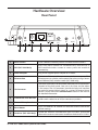
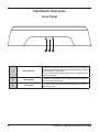
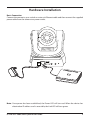
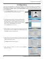
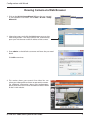
Quick Install Guide
Wireless N /Wired PTZ H.264
Network Camera
This document will guide you through the basic installation
process for your new D-Link Network Camera.
DCS-5605/5635
Documentation also available on CD
and via the D-Link Website
ENGLISH
DCS-5605/5635 Quick Install Guide
This installation guide provides basic instructions for installing the DCS-5605/5635 Network
Camera on your network. For additional information about how to use the camera, please refer
to the User Manual which is located on the CD or from the D-Link support website.
Installation Steps
1. Verify the package contents against the list below
2. Hardware Overview
3. Hardware Installation
4. Configuration with the Setup Wizard
Package Contents
• DCS-5605/5635 Network Camera
• CD-ROM (Software and User Manual)
• CAT5 Ethernet Cable
• Power Adapter
• Two Antennas (DCS-5635 only)
• A/V Cable
• Plate
• Mounting Screws
If any of the above items are missing, please contact your reseller.
2
2
D-Link DCS-5605/5635 Quick Install Guide
ENGLISH
Hardware Overview
Rear Panel
1
WPS
9
2
12V
2A
3
ETHERNET
4
5
LINE/VIDEO
OUT
MIC
RESET
6
7
8
9
1
Micro SD Port
Insert a Micro SD memory card to save data from the camera.
2
WPS (DCS-5635 Only)
Press the WPS button to automatically connec t to a
WPS-enabled wireless router or access point and establish
connectivity.
3
Power Receptor
Plug in the supplied power adapter to an outlet.
4
Ethernet Port
Connect an Ethernet cable to a router, switch, or computer. The
Ethernet port can also be used to power the camera using a Power
over Ethernet (PoE) switch or router (DCS-5605 only).
5
I/O Connector
The camera provides a terminal block with two pairs of connectors
situated on the back panel. One pair is for input and the other
is for output. The I/O connectors provide the physical interface
to send and receive digital signals to a variety of external alarm
devices. Please refer to the I/O Connector section in the manual
for detailed information.
6
Video/Audio Line-Out Port
Plug the included A/V cable into the A/V out connector to use the
camera with a television or VCR, or connect to speakers.
7
External Microphone Port
Insert an external microphone to record audio.
8
Reset Button
Press and hold for 10 seconds to reset the camera back to the
default settings.
9
Antennas (DCS-5635 Only)
Locate the antennas included with your DCS-5635, and attach
them to the antenna connectors located on the back of DCS-5635.
D-Link DCS-5605/5635 Quick Install Guide
3
3
ENGLISH
Hardware Overview
Front Panel
1
4
4
2
3
1
WPS/Link LED
The WPS LED will blink blue when initializing a connection,
and illuminate with solid blue once the connection has been
established (DCS-5635 only).
The Link LED will illuminate green once a connection has
been established.
2
Microphone
The built-in microphone can be used to capture audio from
sources nearby the camera.
3
Power LED
The Power LED will illuminate red when the camera is
receiving power.
D-Link DCS-5605/5635 Quick Install Guide
Basic Connection
Connect the camera to your switch or router via Ethernet cable and then connect the supplied
power cable from the camera to a power outlet.
ENGLISH
Hardware Installation
Note: Once power has been established, the Power LED will turn red. When the device has
obtained an IP address and is accessible, the Link LED will turn green.
D-Link DCS-5605/5635 Quick Install Guide
5
5
ENGLISH
Configuration with Wizard
Configuration
Insert the DCS-5605/5635 CD into your computer's CD-ROM drive to begin the installation.
If the Autorun function on your computer is disabled, or if the D-Link Launcher fails to start
automatically, click Start > Run. Type D:\autorun.exe, where D: represents the drive letter of
your CD-ROM drive.
1. Click Installation Wizard to begin the installation. Install
the Setup Wizard SE and execute the program.
2. The Setup Wizard will appear and display the MAC address
and IP address of your camera(s). If you have a DHCP server
on your network, a valid IP Address will be displayed. If
your network does not use a DHCP server, the camera's
default static IP 192.168.0.20 will be displayed.
Click the Wizard button to continue.
3. Enter the Admin ID and password. When logging in for the first
time, the default Admin ID is admin with the password left blank.
Click Next to proceed to the next page.
4. Select DHCP if your camera obtains an IP address automatically
when it boots up. Select static IP if the camera will use the same IP
address each time it is started.
Click Next to proceed to the next page.
5. Take a moment to confirm your settings and click Restart to
reboot the camera.
6
6
D-Link DCS-5605/5635 Quick Install Guide
Configuration with Wizard
ENGLISH
Viewing Camera via Web Browser
1. Click on the D-Link Setup Wizard SE icon that was created
in your Windows Start menu. Go to Start > D-Link > Setup
Wizard SE.
2. Select the camera and click the Link button to access the
web configuration. The Setup Wizard will automatically
open your web browser to the IP address of the camera.
3. Enter admin as the default username and leave the password
blank.
Click OK to continue.
4. This section shows your camera’s live video. You can
select your video profile and view or operate the camera.
For additional information about web configuration,
please refer to the user manual included on the CD-ROM
or the D-Link website.
D-Link DCS-5605/5635 Quick Install Guide
7
7
Technical Support
D-Link’s website contains the latest user documentation and software updates
for D-Link products. U.S. and Canadian customers can contact D-Link Technical
Support through our website or by phone.
United States
Telephone
(877) 354-6555
World Wide Web
http://support.dlink.com
Canada
Telephone
(877) 354-6560
World Wide Web
http://support.dlink.ca
Version 1.1
October 11, 2010
6DCS5635Q.02G
Copyright ©2010 D-Link Corporation/D-Link Systems, Inc. All rights reserved. D-Link and the D-Link logo are registered trademarks
of D-Link Corporation or its subsidiaries in the United States and other countries. Other trademarks are the property of their
respective owners. Actual data throughput will vary. Network conditions and environmental factors, including volume of network
traffic, building materials and construction, and network overhead lower actual data throughput rate. Product specifications, size
and shape are subject to change without notice, and actual product appearance may differ from that depicted on the packaging.
Visit www.dlink.com for more details.