1
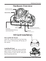
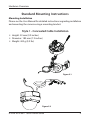
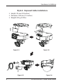
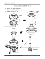
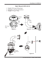
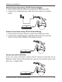
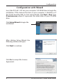
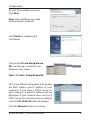
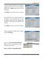
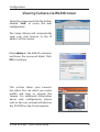
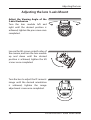
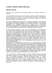
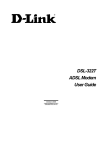
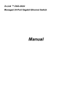
Quick Installation Guide HD Day & Night Vandal-Proof Fixed Dome Network Camera This document will guide you through the basic installation process for your new D-Link Network Camera. DCS-6511 System Requirements DCS-6511 Quick Install Guide This installation guide provides basic instructions for installing the DCS-6511 Network Camera on your network. For additional information about how to use the camera, please see the User’s Manual which is available on the CD included in this package or from the D-Link support website. Installation Steps 1. Verify the package contents against the list below. 2. Hardware Overview 3. SD Card Installation 4. Hardware Installation 5. Configuration with Wizard 6. Adjusting the lens 3-axis Mount Package Contents DCS-6511 Network Camera Manual and Software on CD-ROM Quick Install Guide Power Adapter AV & Power Cables Security Wrench CAT-5 Ethernet Cable Extension Adapter Cable Cover Mounting Bracket and Screws Rubber Plug If any of the above items are missing, please contact your reseller. Safety Notice: Installation and servicing should be done by certified technicians so as to conform to all local codes and prevent voiding your warranty. D-Link DCS-6511 Quick Install Guide 2 Hardware Overview Hardware Overview 24 V Power Connector Connects to 24 V AC power Power Connector Connects to 12 V DC power Audio In Connects to a microphone Ethernet Jack RJ-45 connector for Ethernet which can also be used to power the camera using Power over Ethernet (PoE) DI/DO Wiring, 12V DC output I/O connectors for external devices Audio Out Connects to speakers SD Card Installation Disassemble the Camera Open the camera enclosure by loosening the 4 screws. Lift the dome off the base of the camera. Install the SD Card Push the SD card into the camera with the gold contacts oriented towards the base of the camera. To eject the SD card, push the SD card into the slot. 3 D-Link DCS-6511 Quick Install Guide Hardware Overview Standard Mounting Instructions Mounting Installation Please see the User Manual for detailed instructions regarding installation and mounting the camera using a mounting bracket. Style 1 - Concealed Cable Installation Height: 23 mm (0.9 inches) Diameter: 183 mm (7.2 inches) Weight: 400 g (0.9 lbs) Figure 2.1 Figure 2.2 D-Link DCS-6511 Quick Install Guide 4 Hardware Installation Style 2 - Exposed Cable Installation Height: 23 mm (0.9 inches) Diameter: 183 mm (7.2 inches) Weight: 400 g (0.9 lbs) Figure 2.3 Figure 2.5 5 Figure 2.4 Figure 2.6 D-Link DCS-6511 Quick Install Guide Hardware Installation Pendant Mount (DCS-34-2) Height: 201 mm (7.9 inches) Diameter: 150 mm (5.9 inches) Weight: 665 g (1.45 lbs) Rubber Seal Bracket Cap Pendant Bracket Mounting Plate Figure 3.1 Figure 3.2 Figure 3.4 Figure 3.3 D-Link DCS-6511 Quick Install Guide 6 Hardware Installation Bent Mount (DCS-34-3) Height: 253 mm (9.96 inches) Diameter: 150 mm (5.9 inches) Weight: 770 g (1.7 lbs) Bracket Cap Bent Bracket Mounting Plate Figure 4.1 Figure 4.2 Bracket Cap Bent Bracket Dome Camera Figure 4.3 7 Figure 4.4 D-Link DCS-6511 Quick Install Guide Software Installation General Connection Using 12 V DC Power Adapter 1. Connect the network camera to a hub via an Ethernet cable. 2. Connect the supplied power cable from the camera to a power outlet. General Connection Using 24 V AC Power Wiring 1. Connect the network camera to a hub via an Ethernet cable. 2. Connect the supplied power cable from the camera to a power source such as your building's emergency power. Connection with a PoE Hub If you are using a PoE hub, connect the IP camera to the hub via an Ethernet cable, which will provide the transmission of both power and data over a single cable. D-Link DCS-6511 Quick Install Guide 8 Configuration Configuration with Wizard Insert the DCS-6511 CD into your computer's CD-ROM drive to begin the installation. If the Autorun function on your computer is disabled, or if the D-Link Launcher fails to start automatically, click Start > Run. Type D:\autorun.exe, where D: represents the drive letter of your CD-ROM drive. Click Setup Wizard to begin the installation. After clicking Setup Wizard, the following window will open. Click Next to continue. Click Yes to accept the License Agreement. 9 D-Link DCS-6511 Quick Install Guide Configuration To start the installation process, click Next. Note: The installation may take several minutes to finish. Click Finish to complete the installation. Click on the D-Link Setup Wizard SE icon that was created in your Windows Start menu. Start > D-Link > Setup Wizard SE The Setup Wizard will appear and display the MAC address and IP address of your camera(s). If you have a DHCP server on your network, a valid IP Address will be displayed. If your network does not use a DHCP server, the network camera's default static IP 192.168.0.20 will be displayed. Click the Wizard button to continue. D-Link DCS-6511 Quick Install Guide 10 Configuration Enter the Admin ID and password. When logging in for the first time, the default Admin ID is admin with the password left blank. Click Next, to proceed to the next page. Select DHCP if your camera obtains an IP address automatically when it boots up. Select static IP if the camera will use the same IP address each time it is started. Click Next, to proceed to the next page. Take a moment to confirm your settings and click Restart. Click on the D-Link Setup Wizard SE icon that was created in your Windows Start menu. Start > D-Link > Setup Wizard SE 11 D-Link DCS-6511 Quick Install Guide Configuration Viewing Camera via Web Browser Select the camera and click the button labeled "Link" to access the web configuration. The Setup Wizard will automatically open your web browser to the IP address of the camera. Enter admin as the default username and leave the password blank. Click OK to continue. This section shows your camera’s live video. You can select your video profile and view or operate the camera. For additional information about web configuration, please refer to the user manual included on the CD-ROM or the D-Link website. D-Link DCS-6511 Quick Install Guide 12 Adjusting the Lens Adjusting the lens 3-axis Mount Adjust the Viewing Angle of the 3-axis Mechanism Turn the lens module left and right until the desired position is achieved; tighten the pan screw once completed. Loosen the tilt screws on both sides of the camera, and turn the lens module up and down until the desired position is achieved; tighten the tilt screws once completed. Turn the lens to adjust the IP camera’s image until the desired orientation is achieved, tighten the image adjustment screw once completed. 13 D-Link DCS-6511 Quick Install Guide Notes D-Link DCS-6511 Quick Install Guide 14 Notes 15 D-Link DCS-6511 Quick Install Guide Technical Support D-Link’s website contains the latest user documentation and software updates for D-Link products. U.S. and Canadian customers can contact D-Link Technical Support through our website or by phone. United States Telephone (877) 354-6555 World Wide Web http://support.dlink.com Canada Telephone (877) 354-6560 World Wide Web http://support.dlink.ca Version 1.0 November 11, 2010 RMN0100501 Copyright ©2010 D-Link Corporation/D-Link Systems, Inc. All rights reserved. D-Link and the D-Link logo are registered trademarks of D-Link Corporation or its subsidiaries in the United States and other countries. Other trademarks are the property of their respective owners. Actual data throughput will vary. Network conditions and environmental factors, including volume of network traffic, building materials and construction, and network overhead lower actual data throughput rate. Product specifications, size and shape are subject to change without notice, and actual product appearance may differ from that depicted on the packaging. Visit www.dlink.com for more details. D-Link DCS-6511 Quick Install Guide 16