1
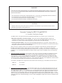
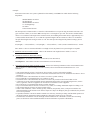
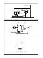
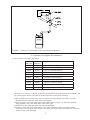
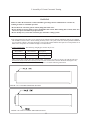
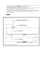
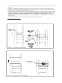
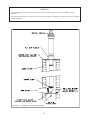
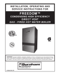
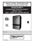
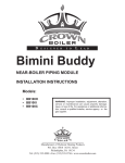
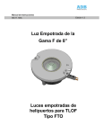
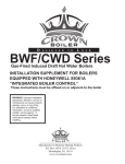
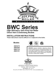
D
E
S
I
G
N
E
D
T
O
L
E
A
D
BWC Series
BWC150/225 CONCENTRIC VENTING
INSTALLATION INSTRUCTIONS
These instructions must be affixed on or adjacent to the boiler.
Models:
• BWC150
• BWC225
WARNING: Improper installation, adjustment, alteration,
service or maintenance can cause property damage, injury,
or loss of life. For assistance or additional information, consult a qualified installer, service agency or the gas supplier.
This boiler requires a special venting system. Read these
instructions carefully before installing.
Manufacturer of Hydronic Heating Products
P.O. Box 14818 3633 I. Street
Philadelphia, PA 19134
Tel: (215) 535-8900 • Fax: (215) 535-9736 • www.crownboiler.com
Table of Contents
A. Concentric Vent System Design
2
B. Concentric Vent Adapter Kit Installation
9
C. Assembly of Crown Concentric Venting and Condensate Drain
11
1
WARNING
FAILURE TO VENT THIS BOILER IN ACCORDANCE WITH THESE INSTRUCTIONS COULD CAUSE
FLUE GAS TO ENTER THE BUILDING RESULTING IN SEVERE PROPERTY DAMAGE, PERSONAL
INJURY, OR DEATH:
* Do not attempt to vent this boiler with galvanized, PVC, or any other vent components not listed in Table 1.6.
* Do not attempt to mix components from different approved vent systems.
* Do not obtain combustion air from within the building.
* Do not install a barometric damper or drafthood on this boiler.
CAUTION
Moisture and ice may form on the surfaces around the vent termination. To prevent deterioration, surfaces
should be in good repair (sealed, painted, etc.).
Concentric Venting For BWC150 and BWC225
A. Concentric Vent System Design
In addition to the vent options listed in the installation manual there are two other ways to vent this boiler:
• Horizontal (“Side Wall”) Concentric Venting - Vent system exits the building through an outside wall.
Concentric venting consists of a “pipe within a pipe”. Flue gas exits the building through the inner pipe and
combustion air is drawn into the boiler through the space between the inner and outer pipe.
• Vertical Concentric Venting - Vent system exits the building through the roof. Concentric venting consists of a
“pipe within a pipe”. Flue gas exits the building through the inner pipe and combustion air is drawn into the boiler
through the space between the inner and outer pipe.
These systems are considered “direct vent” because air for combustion is drawn directly from the outdoors into
the boiler. A description of these venting options are shown in Tables 1.1 and 1.5. For clarity, the vent options
are numbered 3 and 4 for the horizontal options and 8 and 9 for the vertical options. One of the vent option columns
in Tables 1.1 or 1.5 must match the planned vent and air intake system exactly. In addition, observe the following
guidelines:
1) Approved concentric vent systems - The concentric vent system is optional for the BWC150 and BWC225 boilers.
Each Crown concentric vent component consists of an inner pipe of polypropylene and the outer pipe of steel.
Integral gaskets on each concentric fitting provide a gas tight seal. Concentric pipe sizes are called out in terms
of the inner and outer pipe nominal diameters in millimeters. For example, “80/125mm” pipe consists of a 80mm
exhaust pipe inside a 125mm diameter outer pipe. A list of all Crown concentric vent components is shown in Table
1.6. Use only one of the approved concentric vent systems shown in Table 1.6.
A concentric vent adapter kit is required to use these boilers with concentric pipe. Part numbers for these kits are:
BWC150
P/N 230550
BWC225
P/N 230555
2) Maximum Vent and Air Intake Lengths - The maximum length of the vent air intake piping depends upon the vent
option selected and the boiler size. See Table 1.1 or 1.5 for the maximum vent length. In horizontal vent systems,
the lengths shown in Table 1.1 are in addition to the vent components which come with the Air Intake Box Kit and
one standard radius elbow. For vertical vent systems, the maximum vertical vent lengths shown in Table 1.5 are in
addition to the vent components which come with the Air Intake Box Kit and two standard radius elbows. If more
elbows are desired, the maximum allowable vent length must be reduced by the amount shown in Table 1.4 for each
additional elbow used. Termination fittings are never counted, although the length of the concentric terminal section
is counted.
2
Example:
A 80/125mm concentric vent system is planned for a horizontally vented BWC150 which has the following
components:
Standard Radius 90° Elbow
5ft Straight Pipe
Standard Radius 90° Elbow
1-1/2ft Straight Pipe
45° Elbow
Uncut Terminal Section
The Vent Option #3 column in Table 1.1 describes a horizontal direct vent system using 80/125mm concentric vent
pipe. From this column, we see that a BWC150 may have a vent length of up to 55ft The first 90° standard radius
elbow is not considered. The length of the terminal section (not including the terminal itself) is approximately 22.1”
(1.84ft) installed. From Table 1.4, we see that the equivalent length of the 80/125mm 90° elbow is 8.5ft and that
the equivalent length of the 45 degree elbow is 3.0ft. The total equivalent length of the planned venting system is
therefore:
5ft (Straight ) + 8.5ft (90 Elbow) + 1.5ft (Straight ) + 3.0ft (45 Elbow) + 1.84ft (Uncut Terminal Section) = 19.84ft.
Since Table 1.1 shows a maximum allowable vent length of 55ft, the planned vent system length is acceptable.
3) Minimum Vent and Air Intake Lengths - Observe the minimum vent lengths shown in Tables 1.1 and 1.5.
4)
Permitted Terminals for Horizontal Venting:
• Vent Option 3 - 80/125mm Concentric Vent Terminal (Crown PN 230531)
• Vent Option 4 - 100/150mm Concentric Vent Terminal (Crown PN 230569)
5)
Horizontal Vent and Air Intake Terminal Location - Observe the following limitations on the vent terminal location
(also see Figure 1.3). When locating a concentric terminal, observe the limitations outlined below for “vent
terminals”.
• Vent terminal must be at least 1 foot from any door, window, or gravity inlet into the building.
• The bottom of terminal must be at least 12” above the normal snow line. In no case should it be less than 12” above
grade level.
• The bottom of the vent terminal must be at least 7 feet above a public walkway.
• Do not install the vent terminal directly over windows or doors.
• The bottom of the vent terminal must be at least 3 feet above any forced air inlet located within 10 feet.
• A clearance of at least 4 feet horizontally must be maintained between the vent terminal and gas meters, electric
meters, regulators, and relief equipment. Do not install vent terminal over this equipment.
• Do not locate the vent terminal under decks or similar structures.
• Top of vent terminal must be at least 5 feet below eves, soffits, or overhangs. Maximum depth of overhang is 3 ft.
• Vent terminal must be at least 6 feet from an inside corner.
• Under certain conditions, water in the flue gas may condense, and possibly freeze, on objects around the vent
terminal including on the structure itself. If these objects are subject to damage by flue gas condensate, they should
be moved or protected.
• If possible, install the vent and air intake terminals on a wall away from the prevailing wind. Reliable operation of
this boiler cannot be guaranteed if these terminals are subjected to winds in excess of 40 mph.
• Terminal must not terminate in areas that might contain combustion air contaminates, such as near swimming
pools. See Section IV in the installation manual for more information on possible contaminates.
3
TABLE 1.1: SUMMARY OF HORIZONTAL VENTING OPTIONS
VENT OPTION #
3
CLASSIFICATION USED IN THIS
MANUAL
HORIZONTAL
CONCENTRIC
4
HORIZONTAL
CONCENTRIC
ILLUSTRATED IN FIGURE
1.2
1.2
VENT PIPE PENETRATION
THROUGH STRUCTURE
WALL
WALL
AIR INTAKE PIPE PENETRATION
THROUGH STRUCTURE
WALL
WALL
80/125 mm
CONCENTRIC
100/150 mm
CONCENTRIC
VENT PIPE SIZE
MAXIMUM LENGTH
VENT
MINIMUM LENGTH
VENT
AIR INTAKE PIPE SIZE
BWC150
55
INLET
BWC225
55
BWC150
55
BWC225
55
BWC150
2
INLET
BWC225
2
BWC150
2
BWC225
2
VENT TERMINAL
AIR INTAKE TERMINAL
VENT MATERIAL
AIR INTAKE MATERIAL
4
Crown 230531
CONCENTRIC
TERMINAL
Crown 230569
CONCENTRIC
TERMINAL
CROWN
80/125mm
VENT
COMPONENTS
SHOWN IN
TABLE 1.6a
CROWN
100/150mm
VENT
COMPONENTS
SHOWN IN
TABLE 1.6b
FIGURE 1.2: HORIZONTAL CONCENTRIC VENTING
(VENT OPTION 3,4)
6)
Permitted Terminals for Vertical Venting • Vent Option 8 - Use Crown PN 230532 with the appropriate flashing (Table 1.6a)
• Vent Option 9 - Use Crown PN 230570 with the appropriate flashing (Table 1.6b)
7) Vertical Vent Terminal Locations (Vent Options 8,9) - Observe the following limitations on the location of all vertical vent
terminals (see Figure 1.7):
• The top of the vent pipe must be at least 2 feet above any object located within 10 feet.
• The bottom of the air inlet terminal must be at least 12” above the normal snow accumulation that can be expected
on the roof. The terminal used in Vent Options 8 & 9 has a fixed distance above the storm collar of 19”. If a greater
distance is needed to provide the clearance above the snow line, build a chase on the roof and mount the vertical
terminal on top of the chase.
8) Wall thimbles – Concentric vent has a “zero” clearance to combustibles and therefore does not require the use of wall
thimbles.
9) Pitch of Horizontal Piping - Pitch all horizontal piping 5/8” per foot so that any condensate which forms in the piping will
run towards the boiler:
10) Supporting Pipe - Support Crown concentric venting near the female end of each straight section of pipe.
Exception: Vertical runs of concentric pipe in an unused chimney (Figure 1.14) need only be supported at the
terminal and at the base of the run.
5
FIGURE 1.3a: LOCATION OF VENT TERMINAL RELATIVE TO WINDOWS, DOORS, GRADE
FIGURE 1.3b: LOCATION OF VENT TERMINAL RELATIVE TO METERS AND FORCED AIR INLETS
FIGURE 1.3c: POSITIONING VENT TERMINAL UNDER OVERHANGS
6
TABLE 1.4: VENT/ AIR INTAKE FITTING EQUIVALENT LENGTH
VENT FITTING
EQUIVALENT LENGTH (ft)
80/125mm 90° CONCENTRIC ELBOW
8.5
80/125mm 90° SWEEP CONCENTRIC ELBOW
5.5
80/125mm 45° CONCENTRIC ELBOW
3.0
80/125mm 90° CONCENTRIC SUPPORT ELBOW
8.5
100/150mm 90° SWEEP CONCENTRIC ELBOW
8.0
100/150mm 45° CONCENTRIC ELBOW
3.0
100/150mm 90° CONCENTRIC SUPPORT ELBOW
10.0
TABLE 1.5: SUMMARY OF VERTICAL VENTING OPTIONS
VENT OPTION #
8
CLASSIFICATION USED IN THIS
MANUAL
VERTICAL
CONCENTRIC
9
VERTICAL
CONCENTRIC
ILLUSTRATED IN FIGURE
1.7
1.7
VENT PIPE PENETRATION
THROUGH STRUCTURE
ROOF
ROOF
AIR INTAKE PIPE STRUCTURE
THROUGH STRUCTURE
ROOF
ROOF
80/125 mm CONCENTRIC
100/150 mm CONCENTRIC
VENT PIPE SIZE
VENT
BWC150
47
INLET
BWC225
BWC150
45
47
VENT
BWC225
45
BWC150
2
BWC225
INLET
MINIMUM LENGTH
MAXIMUM LENGTH
AIR INTAKE PIPE SIZE
2
BWC150
2
BWC225
VENT TERMINAL
AIR INTAKE TERMINAL
VENT MATERIAL
AIR INTAKE MATERIAL
2
CROWN #230532
CONCENTRIC TERMINAL
(TABLE 1.6a)
CROWN #230570
CONCENTRIC TERMINAL
(TABLE 1.6b)
CROWN 80/125 mm VENT
COMPONENTS SHOWN IN
TABLE 1.6a
CROWN 100/150 mm VENT
COMPONENTS SHOWN IN
TABLE 1.6b
7
TABLE 1.6a: CROWN CONCENTRIC 80/125 VENT COMPONENTS
(VENT OPTIONS 3,8)
CROWN PN
DESCRIPTION
SIZE
USED ON
VENT
OPTION #
230527
90 DEGREE EL (STANDARD)
80/125mm
3,8
230528
90 DEGREE EL (SWEEP)
80/125mm
3,8
COMMENTS
230526
45 DEGREE EL
80/125mm
3,8
230517
19 1/2” STRAIGHT
80/125mm
3,8
230515
39” STRAIGHT
80/125mm
3,8
CAN BE CUT
230518
39” STRAIGHT
80/125mm
3,8
MAY NOT BE CUT
230519
78” STRAIGHT
80/125mm
3,8
MAY NOT BE CUT
230525
TELESCOPING STRAIGHT
80/125mm
3,8
ADJUSTABLE FROM 12-1/2” TO 16-1/2
230531
HORIZONTAL TERMINAL
80/125mm
3
CAN BE CUT
230532
VERTICAL TERMINAL
80/125mm
8
230533
FLAT ROOF FLASHING
80/125mm
8
(NOTE #1)
230535
SLOPED ROOF FLASHING
80/125mm
8
(NOTE #2)
230530
SUPPORT ELBOW WITH
CHIMNEY CHASE BRACKET
80/125mm
8
(NOTE #3)
230536
SUPPORT BAND
80/125mm
3,8
Table 1.6a Notes:
1) Vertical terminal can be used with either of the roof flashings listed beneath it.
2) Sloped roof flashing suitable for roof angles between 25 and 45 degrees.
3) Used at base of vertical run inside unused masonry chimney.
TABLE 1.6b: CROWN CONCENTRIC100/150 VENT COMPONENTS
(VENT OPTIONS 8,9)
SIZE
USED ON
VENT
OPTION #
CROWN PN
DESCRIPTION
COMMENTS
230567
90 DEGREE EL (SWEEP)
100/150mm
4,9
230565
45 DEGREE EL
100/150mm
4,9
230560
19 1/2” STRAIGHT
100/150mm
4,9
CAN BE CUT
230562
39” STRAIGHT
100/150mm
4,9
CAN BE CUT
230561
39” STRAIGHT
100/150mm
4,9
MAY NOT BE CUT
230563
78” STRAIGHT
100/150mm
4,9
MAY NOT BE CUT
230564
TELESCOPING STRAIGHT
100/150mm
4,9
ADJUSTABLE FROM 12-1/2” TO 17-1/2
230569
HORIZONTAL TERMINAL
100/150mm
4
230570
VERTICAL TERMINAL
100/150mm
9
(NOTE #1)
230571
FLAT ROOF FLASHING
100/150mm
9
230572
SLOPED ROOF FLASHING
100/150mm
9
(NOTE #2)
230568
SUPPORT ELBOW WITH
CHIMNEY CHASE BRACKET
100/150mm
9
(NOTE #3)
230573
SUPPORT BAND
100/150mm
4,9
Table 1.6b Notes:
1) Vertical terminal can be used with either of the roof flashings listed beneath it.
2) Sloped roof flashing suitable for roof angles between 25 and 45 degrees.
3) Used at base of vertical run inside unused masonry chimney.
8
FIGURE 1.7: VERTICAL CONCENTRIC VENT SYSTEM (VENT OPTION 6)
B.
Concentric Vent Adapter Kit Installation
1) The Concentric Vent Adapter Kits include:
P/N 230550 P/N 230555 Description
(BWC150) (BWC225)
240470
240480
Rubber Gasket
240471
240481
Air Intake Box
90-054
240472
230539
90-054
240482
230575
#10 x 3/4” Sheet Metal Screws
Stainless Vent Adapter
Concentric Condensate Collector
240552
240550
240552
240550
Condensate Collector Adapter
Tapped Condensate Trap Plug
240560
240560
66”of 1/2” Clear PVC Tubing
240555
240555
90° Hose Barb (2)
240557
240557
1/2” Hose Clamps (2)
Where the use of “silicone” is called for in the following instructions, use GE RTV106 for the vent adapters and
any general-purpose silicone sealant such as GE RTV102 for the air inlet piping connection.
a) Start assembly of the air intake box by first removing the hose clamp shipped on the BWC vent collar.
Bend the three hose clamp tabs on this collar inward slightly.
b) Place the gasket over the vent collar and air intake collar as shown in Figure 1.8. The gasket should fit
snugly against the vent collar and air intake collar with no gaps.
c) Bend the three hose clamp tabs on the vent collar outward slightly.
d) Clean the exterior of the male end and interior of the female end of the stainless vent adapter and the
inside of the vent collar on the boiler. Remove dirt, grease, and moisture from the surfaces to be sealed. Dry
surfaces or allow to dry thoroughly.
9
e) On the male end of the stainless vent adapter, apply a ¼” wide bead of silicone approximately 1/2” from
the end of the pipe.
f) Insert the male end of the stainless vent adapter into the boiler vent collar until it bottoms out.
g) Apply an additional bead of silicone over the outside of the joint and smooth out.
h) Replace and tighten the clamp on the vent collar.
i) Remove one (BWC150) or two (BWC225) of the #10 sheel metal screws on the top of the rear jacket panel
and place the air intake box over the vent and onto the boiler.
j) Use the exposed holes to line up the air intake box and gasket.
k) Insert the concentric condensate collector into the stainless vent adapter and the air intake box until the bead
on the collector bottoms out on the air intake box collar. Turn the fitting so that the threaded stub faces to the
right.
l) Square up the air intake box and the foam rubber gasket to the boiler jacket and loosely attach the box to the
rear jacket panel with one of the previously removed #10 sheet metal screws.
m) Drill a single 1/8” hole through one of the mounting holes on the opposite side of the air intake box and
attach the box to the jacket with one of the #10 sheet metal screws. This will insure the rest of the mounting
holes line up.
n) Drill 1/8” holes in through the remaining mounting holes and attach the air intake box and gasket to the boiler
jacket with the remaining #10 sheet metal screws.
o) Apply pipe thread sealant tape (not supplied) to the 90° barbed hose fittings. Attach one to the condensate
collector adapter and the other to the bottom of the tapped condensate trap plug. (Figures 1.8, 1.15)
p) Attach the condensate collector adapter to the threaded portion of pipe sticking out the side of the concentric
condensate collector so that the hose barb is facing down. Slide one end of the 1/2” clear plastic tubing over
the hose barb and attach the hose clamp.
q) Run the tubing down the right side panel and into the 1-3/8” knockout located on the lower right of the right
side panel. Be sure to remove all burrs from the knockout to prevent the hose from being punctured.
r) Remove the plug and black gasket ring from the bottom of the condensate trap located under the boiler.
s) Reinstall the gasket ring onto the tapped condensate trap plug. Insert the tapped plug (which has the barbed
hose fitting attached to it) in the base of the trap in place of the original plug. Slide the other end of the clear
plastic tubing over the hose barb and attach the hose clamp. (Figure 1.15)
t) Allow the silicone to cure per the silicone manufacturer’s instructions before operating the boiler.
FIGURE 1.8:
CONCENTRIC VENT
ADAPTER ASSEMBLY
10
C. Assembly of Crown Concentric Venting
WARNING
Failure to follow the instructions could result in flue gas leakage into the combustion air or indoor air,
resulting in unsafe or unreliable operation.
• Do not lubricate concentric gaskets with anything other than water.
• Do not attempt to cut any piping except as permitted in this section. When cutting these sections, make sure
all cuts are square and allow for proper insertion.
• Do not attempt to try to mix this concentric pipe with other venting systems.
1) The components listed in Table 1.6 are required for 80/125mm and 100/150mm installations and are not supplied
with the BWC150/225 boilers. Before starting assembly of the vent system, make sure that the planned installation
is in accordance with the “Vent System Design” section of this manual and that all required vent components are on
hand. These components are available through Crown distributors.
2) Cutting Straight Pipe - The following straight pipe sections may be cut:
80/125 Part #
100/150 Part #
230517
230515
230560
230562
Description
19 1/2” Straight
39” Straight
These sections have a plain male end (without beads - see Figure 1.9a). They are always cut from the male end.
Sections not shown on the above list may not be cut. These sections have beads on the male end (Figure 1.9b).
To cut the straight sections listed above refer to Figure 1.10 and the following instructions:
FIGURE 1.9a: CUTTABLE STRAIGHT SECTION
FIGURE 1.9b: NON CUTTABLE STRAIGHT SECTION
11
a) Determine the required length of the outer pipe. When doing this allow an additional 1” of length for insertion
into the female end of the adjoining pipe. Mark the cut line on the outer pipe.
b) Remove the plastic inner pipe by pulling it out from the female end.
c) Cut the OUTER PIPE ONLY at the point marked in Step (a) using aviation shears, a hacksaw, or an abrasive
wheel cutter. Be careful to cut the pipe square. De burr the cut end with a file or emery cloth.
d) Make an insertion mark 1” from the male end of the outer pipe.
e) Cut the plastic inner pipe so that it will protrude 3/8” beyond the male end of the outer pipe when reinstalled
in the outer pipe. Use a fine tooth hacksaw or a PVC saw to cut the plastic pipe and be careful to cut the pipe
square. De burr the cut edge of the plastic pipe with a file, razor blade, or fine sandpaper.
f) Reinstall the inner pipe.
3) Joining Pipe -
FIGURE 1.10: CUTTING STRAIGHT PIPE
12
a) Start assembly of the vent system at the boiler. Lubricate the brown gasket in the boiler vent collar with a few drops
of water.
b) Push the male end of the first fitting into the boiler collar until it bottoms out. The male end of cuttable sections
should go 1” into the collar until the insertion mark (made in Step 2d above) is covered. On other fittings, the bead
on the male pipe will bottom out on the collar (Figure 1.11b).
c) The male end of cuttable fittings must be held to the collar with three #10 x 1/2” sheet metal screws. Drill a 1/8 hole
through both outer pipes to start this screw. Use a drill stop or other means to ensure that the drill bit does not
penetrate more than 3/8” into the outer pipe. Do not use a sheet metal screw longer than 1/2” (Figure 1.11a).
d) Use locking bands (provided with all fittings) to secure non-cuttable pipe, as well as fittings, to the boiler collar
(Figure 1.11b).
e) Use the same method to join all remaining vent components except for the terminal.
4) Horizontal Terminal Installation
FIGURE 1.11a: JOINING CUTTABLE PIPE
FIGURE 1.11b: JOINING NON CUTTABLE PIPE
13
a) Cut a 5-1/2” diameter hole through the exterior wall at the planned location of the horizontal terminal.
b) Measure distance “L” from the outside surface of the exterior wall to the end of the last fitting as shown in
Figure 1.12a.
c) Add 1-1/4” to distance “L”. Carefully mark this length on the pipe as shown in Figure 1.12b.
d) Remove the aluminum inner pipe from the terminal, by gently pulling on it from the male end. Set aside.
e) Cut the outer pipe only at the point marked in Step (c) using aviation shears, a hacksaw, or an abrasive
wheel cutter. Be careful to cut the pipe square. De-burr the cut end with a file or emory cloth.
f) Reinstall the aluminum inner pipe in the terminal, making sure that the female end of this pipe is
completely bottomed out over the aluminum male connection visible behind the air intake grill. Place a
mark on the aluminum inner pipe 3/8” beyond the end of the outer pipe (Figure 1.12c). Use a fine tooth
hacksaw or hand shears to cut the aluminum pipe and be careful to cut the pipe square (if necessary, the
aluminum pipe can be removed from the terminal again for cutting). De-burr the cut edge of the aluminum
pipe with a file or fine sandpaper.
g) Make a mark on the terminal section 1” from the cut end of the outer pipe as shown in Figure 1.12c.
h) Slip the terminal section through the wall from the outside. Pass the terminal through the inner wall plate
and push into the last section of vent pipe until the mark made in Step (h) is not longer visible (Figure
1.12d). Secure the terminal to the last piece of pipe with three #10 x 1/2” sheet metal screws. Drill a 1/8
hole through both outer pipes to start these screws. Use a drill stop or other means to ensure that the
drill bit does not penetrate more than 3/8” into the outer pipe. Do not use a sheet metal screw longer
than 1/2”.
i) Slip the outer wall plate over the terminal and secure to the wall (Figure 1.12d). Apply a 1/8” bead of
weather resistant RTV over the joint between the outside wall plate and the terminal. Secure the other wall
plate to the inside wall.
FIGURE 1.12a: DIMENSION “L”, HORIZONTAL TERMINAL
FIGURE 1.12b: CUTTING OUTER PIPE OF HORIZONTAL TERMINAL
14
FIGURE 1.12c: CUTTING INNER PIPE OF HORIZONTAL TERMINAL
FIGURE 1.12d: COMPLETING HORIZONTAL TERMINAL INSTALLATION
15
6) Vertical Terminal Installation - In addition to the vertical terminal, either a Flat Roof Flashing (80/125 PN
230533, 100/150 PN 230571) or Sloped Roof Flashing (80/125 PN 230535, 100/150 PN 230572) is required for
this installation.
a) Determine the center line of the terminal location on the roof. If the roof is flat, cut a 5-1/2” diameter hole for
the 80/125 terminal and a 6-1/2” diameter hole for the 100/150 terminal. If the roof is sloped, cut a hole large
enough for the terminal to pass through the roof while remaining plumb. Caution: If the boiler is installed
directly under the hole, cover it while cutting the hole to prevent saw dust and other debris from falling
into the boiler.
b) Install the roof flashing using standard practice for the roofing system on the structure.
c) If not already done, assemble the venting system inside the building. The last section of pipe needs to be on the
same center line as the terminal and within 19-1/4” (80/125) or 28” (100/150) of the top edge of the roof flashing
(Figure 1.13a).
d) Measure distance “H” from the top edge of the storm collar to the end of the last fitting as shown in Figure 1.13a.
e) Add 1” to distance “H”. Carefully mark this length on the pipe as shown in Figure 1.13b.
f) Cut the outer pipe only at the point marked in Step (e) using aviation shears, a hacksaw, or an abrasive wheel
cutter. Be careful to cut the pipe square. De-burr the cut end with a file or emery cloth.
g) Place a mark on the aluminum inner pipe 3/8” beyond the end of the outer pipe (Figure 1.13b). Use a fine tooth
hacksaw to cut the aluminum pipe and be careful to cut the pipe square. De-burr the cut edge of the aluminum
pipe with a file or emery cloth.
h) Make a mark on the terminal section 1” from the cut end of the outer pipe as shown in Figure 1.13b.
i) Slip the terminal section through the roof from the outside. Push into the last section of vent pipe until the mark
made in Step (h) is not longer visible. Secure the terminal to the last piece of pipe with three #10 x 1/2” sheet
metal screws. Drill a 1/8” hole through both outer pipes to start these screws. Use a drill stop or other means
to ensure that the drill bit does not penetrate more than 3/8” into the outer pipe. Do not use a sheet metal
screw longer than 1/2”.
j) Secure the terminal section to the inside of the roof structure using the mounting bracket provided with the
terminal (Figure 1.13c).
7) Chimney Chase Installation - A vertical vent system can be installed in an unused masonry chimney. This
installation is similar to other vertical installations with the following exceptions (Also see Figure 1.14):
a) The chimney chase elbow kit (80/125 PN230530, 100/150 PN 230568) is used at the base of the chimney. This
kit consists of a support elbow and a mounting bracket. Slip the elbow over the M10 x 35 screw in the support
bracket. Determine the desired vertical location of the support elbow in the chimney and mark the location of
the pin on the back of the support bracket on the back wall of the chimney. Drill a 7/16”dia x 2-1/2” deep hole
at this location to support the back of the bracket. The front of the elbow mounting bracket is supported by the
bottom of the opening into the chimney or by an installer supplied bracket.
b) Construct a weather-tight flat roof to cover the top of the old chimney. Install the vertical terminal through this
roof using the flat roof flashing.
FIGURE 1.13a: DIMENSION “H”
16
FIGURE 1.13b: CUTTING VERTICAL TERMINAL
FIGURE 1.13c: COMPLETING VERTICAL TERMINAL INSTALLATION
17
WARNING
• Do not attempt to construct a vertical vent system inside a chimney that is used to vent a fireplace or other
appliances.
• Do not attempt to construct a vertical vent system inside a chimney flue adjacent to another flue used by a fireplace
or other appliances.
FIGURE 1.14: CHIMNEY CHASE INSTALLATION
18
8) Condensate Drain Line - In systems where a concentric vent is used, all condensate which forms in the boiler or
vent system collects in both the condensate vent adapter and the sump under the heat exchanger and leaves the
boiler through the condensate trap. This trap allows condensate to drain from the boiler and vent while retaining
flue gases. A length of corrugated drain hose is supplied with the boiler and is connected to the trap as shown
in Figure 1.15. This hose may be routed through the back of the boiler or to the left side through the knockout
provided. Route this hose to a drain or other suitable point for disposal. Note the following when disposing of the
condensate:
a)
If the condensate drain line must be extended, construct the extension from PVC or CPVC pipe. Insert the
hose provided with the boiler into the end of the extension as shown in Figure 1.15.
b) Condensate is slightly acidic. Do not use metallic pipe or fittings in the condensate drain line. Do not route
the drain line through areas that could be damaged by leaking condensate.
c) Some jurisdictions may require that the condensate be neutralized before being disposed of. Dispose of
condensate in accordance with local codes.
d) Do not route, or terminate, the condensate drain line in areas subjected to freezing temperatures.
e) If the point of condensate disposal is above the trap, it will be necessary to use a condensate pump to
move the condensate to the drain. In such cases, select a condensate pump that is approved for use
with condensing furnaces. If overflow from this pump would result in property damage, select a pump
with an overflow switch and use this switch to shut down the boiler. Alternatively, if heat is a necessity,
use the overflow switch to trigger an alarm.
f) Do not attempt to move the trap from the location shown in Figure 1.15. Do not attempt to substitute
another trap for the one provided with the boiler.
g) The vent shown in Figure 1.15 must be left open for the trap to work properly.
FIGURE 1.15: CONDENSATE DRAIN LINE ASSEMBLY
19
Manufacturer of Hydronic Heating Products
P.O. Box 14818 3633 I. Street
Philadelphia, PA 19134
Tel: (215) 535-8900 • Fax: (215) 535-9736 • www.crownboiler.com
PN: 980241 Rev. 0
BWC - 12/07