1
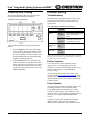
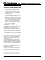
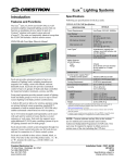
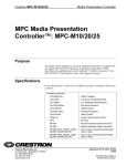
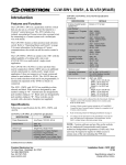
iLux™ Integrated Lighting Systems w/infiNET™
Introduction
Features and Functions
The iLux™ units, CLS-C6RF and CLS-C6MRF, are wallmounted complete integrated lighting systems that can
function as standalone devices and/or be part of a Crestron®
solution total control system network (Cresnet®). The units
are functionally identical except that the CLS-C6MRF
includes a built-in motion sensor.
CLS-C6MRF with Cover Open, Shown in Almond
Each unit is available in three colors: almond, black, or
white. The letter at the end of the product name, ‘A’, ‘B’, or
‘W’, denotes the color (e.g., a CLS-C6MRFA is an almond
unit).
Specifications
Following are specifications for the iLux units.
CLS-C6RF & CLS-C6MRF Specifications
DETAILS
SPECIFICATION
Power Requirements
Line Power, 120 VAC, 60Hz
1
Load Ratings
Max load per channel
800 W/VA
(6.6 Amps @ 120 VAC),
Expandable via Expansion
Modules (sold separately)
15 W/VA
(0.125 Amps @ 120 VAC)
1920 W/VA
(16 Amps @ 120 VAC)
Min load per channel
Max load per unit
Note that if the unit is fed from an arc fault circuit interrupter
(required if controlling loads in a bedroom), the maximum total
load is 1000 W/VA
Load Types
Each unit provides automated control of up to six channels
of lighting loads, including incandescent, magnetic lowvoltage, neon/cold cathode, and two-wire dimmable
fluorescent. Each unit also provides automated control of up
to six groups of shade and drape controllers for motorized
window treatments, screens, and lifts.
Front panel operation provides manual control of lighting
loads and shade groups as well as access to up to sixteen
scenes (lighting level/shade position combinations).
A built-in IR receiver allows for wireless operation using an
optional infrared remote generating standard RC5
commands; a built-in motion detector (CLS-C6MRF only)
enables automated control based on room occupancy.
Up to 16 Crestron keypads (sold separately) can be used
with each unit for control of rooms that have several
entrances or work areas. Each unit also supports up to eight
additional CLS-C6RF units, enabling systems of up to 54
lighting channels and 54 shade groups.
The CLS-C6RF employs Crestron's infiNET technology to
enable a wireless link to a 2-Series control system. A single
C2N-MNETGW gateway connected to the control system
enables 2-way wireless communications between the iLux
system and the central control system, allowing iLux's
functions to be controlled from touchpanels, RF wireless
remotes, and even computers.
Crestron Electronics, Inc.
15 Volvo Drive Rockleigh, NJ 07647
Tel: 888.CRESTRON
Fax: 201.767.7576
www.crestron.com
1
Incandescent, magnetic low
voltage, neon/cold cathode,
dimmable 2-wire fluorescent,
and non-dim lighting
(also: electronic low voltage,
3-wire and 4-wire fluorescent,
High-Inrush Switching, and
277V via expansion modules;
sold separately)
IR Receiver
For use with Crestron IR
remote (sold separately).
RF Wireless
RF Transceiver
2-way RF, 2.4 GHz ISM
Channels 11-26 (2400 to
2483.6 MHz), IEEE 802.15.4
compliant
150 feet indoor, 250 feet
outdoor; subject to site-specific
conditions; range is increased
by adding additional devices or
C2N-MNETRPT repeater;
Requires a C2N-MNETGW RF
gateway
Range (typical)
Gateway
Motion Detector
(CLS-C6MRF only)
Type
Range
Infrared
20 to 30 feet at 4-foot elevation
Default MNET ID
1F
Control System Update Files
2-Series Control System
2, 3
Firmware
Version 2.004.CUZ or later
CLS-C6.v1.0.upg or later
(Continued on following page)
Installation Guide – DOC. 6416A
(2013966)
06.08
Specifications subject to
change without notice.
iLux™ Integrated Lighting Systems w/infiNET™
CLS-C6RF & CLS-C6MRF Specifications (Continued)
DETAILS
SPECIFICATION
Environmental Temperature
32° to 104°F (0° to 40°C)
Humidity
10% to 90% RH
(non-condensing)
Overall Dimensions:
Height
Width
Depth
Weight
4.48 in
8.89 in
2.47 in
2.60 in
(11.38 cm)
(22.58 cm)
(6.25 cm) for CLS-C6
(6.61 cm) for CLS-C6M
Important Notes
Read before installation.
•
•
•
22.8 oz (646.37 g)
1. Additional load types can be controlled and load ratings can be increased via
optional CLS-EXP expansion modules. Refer to the Crestron website
http://www.crestron.com/ for details.
2. The latest software versions can be obtained from the Crestron website. Refer to
the NOTE following these footnotes.
3. Crestron 2-Series control systems include the AV2 and PRO2. Consult the latest
Crestron Product Catalog for a complete list of 2-Series control systems.
NOTE: Crestron software and any files on the website are
for Authorized Crestron dealers and Crestron Authorized
Independent Programmers (CAIP) only. New users may be
required to register to obtain access to certain areas of the
site (including the FTP site)
Physical Description
The following illustration shows the overall dimensions for
the CLS-C6RF and CLS-C6MRF.
CLS-C6MRF Overall Dimensions
•
•
•
Codes: Install in accordance with all local and
national electrical codes.
Wiring: Use copper wire only. For supply
connections, use wires rated for at least 75°C.
Lighting Load Types: incandescent, magnetic
low voltage, neon/cold cathode, dimmable
2-wire fluorescent, and non-dim lighting
(also: electronic low voltage, 3-wire and 4-wire
fluorescent, and 277V via expansion modules; sold
separately).
Temperature: The iLux units are designed for use
where temperatures are between 32° to 104°F
(0° to 40°C).
Wallboxes: The iLux units mount in standard
4-gang wallboxes; 3.5 inches deep, minimum.
Make certain that power is turned off, and
ensure that there is at least 4.5 inches of open
space above and below the electrical box location
to permit heat dissipation.
Installation
WARNING: Turn off power at the distribution panel
circuit breaker. Installing with power on can result in
serious personal injury and damage to the device.
CAUTION: To reduce the risk of overheating and possible
damage to other equipment, do not install to control a
receptacle or a motor-operated appliance.
NOTE: The CLS-C6RF units require a neutral wire for
operation. If no neutral is present, contact a licensed
electrician for installation.
The following tools/hardware are required for installation.
Industry Compliance
This product is Listed to applicable UL Standards and
requirements by Underwriters Laboratories Inc.
(E103692)
NOTE: This device complies with part 15 of the FCC
rules. Operation is subject to the following two conditions:
(1) this device may not cause harmful interference, and (2)
this device must accept any interference received, including
interference that may cause undesired operation.
•
A 4-gang electrical box (not supplied), 3.5 inches
deep, minimum.
•
Phillips torque screwdriver (not supplied)
•
Four 7/8-inch pan head Phillips screws (supplied)
If the planned configuration includes connection to shade
controllers, keypads, and/or a Crestron 2-Series control
system, the following items are also required. Refer to the
latest version of the Crestron CLS-C6RF iLux Integrated
Lighting System w/infiNET Operations Guide (Doc. 6418)
for detailed configuration options.
•
Cresnet network cable(s) (not supplied)
•
Terminal block connector(s) (two supplied)
2 • iLux™ Integrated Lighting Systems w/infiNET™: CLS-C6RF & CLS-C6MRF
Installation Guide – DOC. 6416A
iLux™ Integrated Lighting Systems w/infiNET™
Check that any required Cresnet wiring has been installed
and verified. Then, use the following procedure to install
the iLux unit (CLS-C6MRF is shown in the illustrations).
1.
2.
Feed the wires (power line from the distribution
panel, load wires, plus any required Cresnet
cables) through the holes in the wallbox. Then
install the box in the wall.
Hold the rear of the CLS-C6MRF unit and remove
the front panel and cover assembly by carefully
pulling out and up from the bottom edge.
3.
Remove the control panel overlay from the unit (it
lifts off – is held in place by small tabs) to reveal
the upper mounting screw holes.
4.
Refer to the following diagram for connection of
the AC wiring. All wires to be inserted in the
Installation Guide – DOC. 6416A
screw terminals should be stripped 7/16-inch, and
screws should be tightened to between 8 and 10
in.-lbs. (0.90 Newton meters to 1.13 Newton
meters). The maximum wire size is 12 AWG.
5.
Connect each load wire to the corresponding
LOAD terminals on the unit, connect the power
line hot wire from the circuit breaker to the HOT
terminal on the unit, connect all neutral wires to
the NEUTRAL terminal on the unit, and connect
all ground wires to the (ground) terminal on the
unit.
6.
If Cresnet cabling is part of the installation, attach
the supplied terminal block connector to the
Cresnet cable and plug into the LOCAL
DEVICES port on the unit. Make certain that
there is a minimum 1/4-inch separation between
the Class 2 Cresnet wiring and the Class 1 AC
wiring.
7.
Carefully tuck all wires into the wallbox and fasten
the unit to the wallbox using the four 7/8-inch
Phillips screws supplied.
8.
Reattach the control panel overlay to the front
panel by inserting the four tabs into the slots
provided, and install the hinged front cover
assembly by lining it up at the top and pressing the
bottom edge until it snaps into position.
iLux™ Integrated Lighting Systems w/infiNET™: CLS-C6RF & CLS-C6MRF • 3
iLux™ Integrated Lighting Systems w/infiNET™
Power up and Testing
Problem Solving
The following illustration shows the front panel of the
unit and the controls used during installation.
Troubleshooting
Front Panel Controls and Indicators
The table after this paragraph provides corrective action
for possible trouble situations. If further assistance is
required, please contact a Crestron customer service
representative.
CLS-C6RF/C6MRF Installation Troubleshooting
TROUBLE
Unit does not
function.
Verify the basic installation and wiring connections as
follows:
1.
2.
Press the Lights button to enable manual light
control, and press the right side and the left side
of each of the function buttons to increase and
decrease the lighting level of those loads. Verify
that the intended loads and corresponding LED
bargraphs respond appropriately.
Press the OFF button to turn off all loads. The
loads will ramp down to off while the two-digit
display counts down to off (blank). Two seconds
after all lights have turned off, the unit’s master
air-gap relay opens making it safe to service the
lighting installations.
POSSIBLE
CAUSE(S)
CORRECTIVE ACTION
Unit is not
receiving
line power.
Verify that the unit is properly
connected to the power line and
that the circuit breaker is
closed.
Loads are
not
connected.
Verify that the loads are
operational and that they are
connected to the iLux unit.
Loads turn on
and off, but do
not dim.
Wrong load
type
settings.
Correct load type settings. *
Lights flicker
at low levels
Incorrect
low-end
limit setting.
Change low-end limit setting. *
* Refer to the latest version of the Crestron CLS-C6RF iLux Integrated
Lighting System w/infiNET Operations Guide (Doc. 6418), for details
on setting load types and low-end limits.
Further Inquiries
If you cannot locate specific information or have
questions after reviewing this guide, please take
advantage of Crestron's award winning customer service
team by calling Crestron at 1-888-CRESTRON
[1-888-273-7876].
You can also log onto the online help section of the
Crestron website (www.crestron.com/onlinehelp) to ask
questions about Crestron products. First-time users will
need to establish a user account to fully benefit from all
available features.
Future Updates
As Crestron improves functions, adds new features, and
extends the capabilities of the CLS-C6RF and the
CLS-C6MRF, additional information may be made
available as manual updates. These updates are solely
electronic and serve as intermediary supplements prior to
the release of a complete technical documentation
revision.
Check the Crestron website periodically for manual
update availability and its relevance. Updates are
identified as an “Addendum” in the Download column.
4 • iLux™ Integrated Lighting Systems w/infiNET™: CLS-C6RF & CLS-C6MRF
Installation Guide – DOC. 6416A
iLux™ Integrated Lighting Systems w/infiNET™
Return and Warranty Policies
Merchandise Returns / Repair Service
1.
No merchandise may be returned for credit, exchange or service
without prior authorization from CRESTRON. To obtain
warranty service for CRESTRON products, contact an authorized
CRESTRON dealer. Only authorized CRESTRON dealers may
contact the factory and request an RMA (Return Merchandise
Authorization) number. Enclose a note specifying the nature of
the problem, name and phone number of contact person, RMA
number and return address.
2.
Products may be returned for credit, exchange or service with a
CRESTRON Return Merchandise Authorization (RMA) number.
Authorized returns must be shipped freight prepaid to
CRESTRON, 6 Volvo Drive, Rockleigh, N.J. or its authorized
subsidiaries, with RMA number clearly marked on the outside of
all cartons. Shipments arriving freight collect or without an RMA
number shall be subject to refusal. CRESTRON reserves the right
in its sole and absolute discretion to charge a 15% restocking fee
plus shipping costs on any products returned with an RMA.
3.
Return freight charges following repair of items under warranty
shall be paid by CRESTRON, shipping by standard ground
carrier. In the event repairs are found to be non-warranty, return
freight costs shall be paid by the purchaser.
CRESTRON Limited Warranty
CRESTRON ELECTRONICS, Inc. warrants its products to be free from
manufacturing defects in materials and workmanship under normal use
for a period of three (3) years from the date of purchase from
CRESTRON, with the following exceptions: disk drives and any other
moving or rotating mechanical parts, pan/tilt heads and power supplies
are covered for a period of one (1) year; touchscreen display and overlay
components are covered for 90 days; batteries and incandescent lamps
are not covered.
This warranty extends to products purchased directly from CRESTRON
or an authorized CRESTRON dealer. Purchasers should inquire of the
dealer regarding the nature and extent of the dealer's warranty, if any.
CRESTRON shall not be liable to honor the terms of this warranty if the
product has been used in any application other than that for which it was
intended, or if it has been subjected to misuse, accidental damage,
modification, or improper installation procedures. Furthermore, this
warranty does not cover any product that has had the serial number
altered, defaced, or removed.
This warranty shall be the sole and exclusive remedy to the original
purchaser. In no event shall CRESTRON be liable for incidental or
consequential damages of any kind (property or economic damages
inclusive) arising from the sale or use of this equipment. CRESTRON is
not liable for any claim made by a third party or made by the purchaser
for a third party.
CRESTRON shall, at its option, repair or replace any product found
defective, without charge for parts or labor. Repaired or replaced
equipment and parts supplied under this warranty shall be covered only
by the unexpired portion of the warranty.
Except as expressly set forth in this warranty, CRESTRON makes no
other warranties, expressed or implied, nor authorizes any other party to
offer any warranty, including any implied warranties of merchantability
or fitness for a particular purpose. Any implied warranties that may be
imposed by law are limited to the terms of this limited warranty. This
warranty statement supercedes all previous warranties.
Trademark Information
All brand names, product names and trademarks are the sole property of their respective
owners. Windows is a registered trademark of Microsoft Corporation.
Windows95/98/Me/XP/Vista and WindowsNT/2000 are trademarks of Microsoft Corporation.
Installation Guide – DOC. 6416A
iLux™ Integrated Lighting Systems w/infiNET™: CLS-C6RF & CLS-C6MRF • 5
iLux™ Integrated Lighting Systems w/infiNET™
This page is intentionally left blank.
6 • iLux™ Integrated Lighting Systems w/infiNET™: CLS-C6RF & CLS-C6MRF
Installation Guide – DOC. 6416A