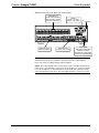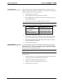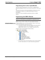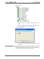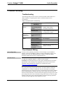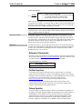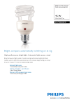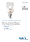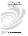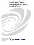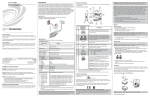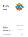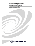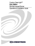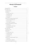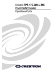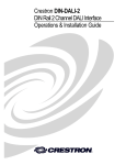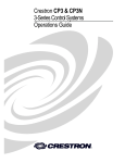
1
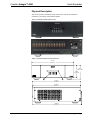
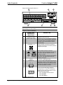
Crestron Adagio™ AAE
Audio Expander
Operations Guide
This document was prepared and written by the Technical Documentation department at:
Crestron Electronics, Inc.
15 Volvo Drive
Rockleigh, NJ 07647
1-888-CRESTRON
Important Safety Instructions
•
Read these instructions.
•
Keep these instructions.
•
Heed all warnings.
•
Follow all instructions.
•
Do not use this apparatus near water.
•
Clean only with dry cloth.
•
Do not block any ventilation openings. Install in accordance
with the manufacturer’s instructions.
•
Do not install near any heat sources such as radiators, heat
registers, stoves, or other apparatus (including amplifiers) that
produce heat.
•
Do not defeat the safety purpose of the polarized or groundingtype plug. A polarized plug has two blades with one wider than
the other. A grounding-type plug has two blades and a third
grounding prong. The wide blade or the third prong are
provided for your safety. If the provided plug does not fit into
your outlet, consult an electrician for replacement of the
obsolete outlet.
•
Protect the power cord from being walked on or pinched
particularly at plugs, convenience receptacles, and the point
where they exit from the apparatus.
WARNING:
TO REDUCE THE RISK OF FIRE OR ELECTRIC SHOCK,
DO NOT EXPOSE THIS APPARATUS TO RAIN OR
MOISTURE. THE APPARATUS SHALL NOT BE
EXPOSED TO DRIPPING OR SPLASHING. OBJECTS
FILLED WITH LIQUIDS, SUCH AS VASES, SHOULD
NOT BE PLACED ON THE APPARATUS.
WARNING:
•
Only use attachments/accessories specified by the
manufacturer.
•
Unplug this apparatus during lightning storms or when unused
for long periods of time.
•
Refer all servicing to qualified service personnel. Servicing is
required when the apparatus has been damaged in any way,
such as power-supply cord or plug is damaged, liquid has been
spilled or objects have fallen into the apparatus, the apparatus
has been exposed to rain or moisture, does not operate
normally, or has been dropped.
•
Disconnect power prior to connecting or disconnecting
equipment.
•
Do not install in direct sunlight.
•
The apparatus must be installed in a way that the power cord
can be removed either from the wall outlet or from the device
itself in order to disconnect the mains power.
•
TO PREVENT ELECTRIC SHOCK, DO NOT REMOVE
COVER. THERE ARE NO USER SERVICEABLE PARTS
INSIDE. ONLY QUALIFIED SERVICE PERSONNEL
SHOULD PERFORM SERVICE.
The lightning flash with arrowhead symbol, within an
equilateral triangle, is intended to alert the user to the
presence of uninsulated “dangerous voltage” within the
product’s enclosure that may be of sufficient magnitude to
constitute a risk of electric shock to persons.
The exclamation point within an equilateral triangle is
intended to alert the user to the presence of important
operating and maintenance (servicing) instructions in the
literature accompanying the appliance.
WARNING:
THIS IS AN APPARATUS WITH CLASS I
CONSTRUCTION. IT SHALL BE CONNECTED TO AN
ELECTRICAL OUTLET WITH AN EARTHING GROUND
TERMINAL.
IMPORTANT:
The AAE can be used with Class 2 output wiring.
Prevent foreign objects from entering the device.
All brand names, product names and trademarks are the property of their respective owners.
©2006 Crestron Electronics, Inc.
Crestron Adagio™ AAE
Audio Expander
Contents
Audio Expander: Adagio AAE
1
Introduction ............................................................................................................................... 1
Features and Functions ................................................................................................ 1
Applications................................................................................................................. 1
Specifications .............................................................................................................. 2
Physical Description.................................................................................................... 3
Industry Compliance ................................................................................................... 5
Setup .......................................................................................................................................... 6
Network Wiring........................................................................................................... 6
Identity Code ............................................................................................................... 6
Hardware Hookup ....................................................................................................... 6
Programming Software .............................................................................................................. 9
Earliest Version Software Requirements for the PC ................................................... 9
Programming with Adagio Composer ......................................................................... 9
Programming with Crestron SystemBuilder.............................................................. 10
Programming with SIMPL Windows ........................................................................ 10
Uploading and Upgrading........................................................................................................ 12
Establishing Communication..................................................................................... 12
Programs and Firmware ............................................................................................ 12
Problem Solving ...................................................................................................................... 13
Troubleshooting......................................................................................................... 13
Check Network Wiring.............................................................................................. 13
Reference Documents................................................................................................ 14
Further Inquiries ........................................................................................................ 14
Future Updates .......................................................................................................... 14
Return and Warranty Policies .................................................................................................. 15
Merchandise Returns / Repair Service ...................................................................... 15
CRESTRON Limited Warranty................................................................................. 15
Operations Guide – DOC. 6460A
Contents • i
Crestron Adagio™ AAE
Audio Expander
Audio Expander: Adagio AAE
Introduction
Features and Functions
•
•
•
•
•
•
•
•
•
•
High performance audio distribution, multi-channel amplifier
Out-of-the-box functionality (no programming required) if used with
the Adagio Entertainment System
Multi-room audio routing for up to six amplified room outputs from as
many of 10 stereo sources
Independent software-driven room select, room on-off, volume, bass,
treble, balance, loudness, stereo/mono and mute controls available on
every room output
12 channel power amplifier
45 watts per channel supports up to six pairs of speakers
Compatible with any Crestron 2-Series control system
Six powered built-in Cresnet® ports
LOOP-THRUs for connection to Adagio control unit or 2-Series
control system and additional AAE units
Available in both domestic (AAE) and international (AAEI) versions
Applications
The following diagram shows how an Adagio home entertainment system, using outof-the-box functionality, might be configured to include the Adagio AAE Audio
Expander.
Adagio System Showing the AAE in a Typical Application
Operations Guide – DOC. 6460A
Audio Expander: Adagio AAE • 1
Audio Expander
Crestron Adagio™ AAE
Specifications
Specifications for the Adagio AAE Audio Expander are listed in the following table.
Adagio AAE Audio Expander Specifications
SPECIFICATION
DETAILS
Audio
Controls
Volume, Balance, Bass, Treble, Loudness,
Mute, On/Off, Room On/Off, Source Select,
Mono/Stereo and Input Compensation
Volume Gain
-80 to +20dB in 1dB steps
Mute
-100dB (electronic),
-120dB (amp output relay)
Input Compensation
±10dB
Bass Gain Range
±12dB @ 100Hz (2dB increments)
Treble Gain Range
±12dB @ 10kHz (2dB increments)
Frequency Response
20Hz to 20kHz ±0.75dB
S/N Ratio
100dB, 20 Hz to 20kHz A-weighted
THD+N
0.05%, 20Hz to 20kHz
Stereo Separation
>75dB
Power
Internal (consumption)
7 Amps, 120 Volts AC @ 60Hz (AAE)
3.5 Amps, 230 Volts AC @ 50Hz (AAEI)
Available Cresnet Power
(output)
50 Watts (2.08 Amps @ 24 Volts DC)
Heat Dissipation
8-ohm impedance
4-ohm impedance
700 BTU/hr
800 BTU/hr
Default NET ID
31
Operating Environment
41° to 104°F (5° to 40°C)
10% to 90% RH (non-condensing)
Enclosure
Black metal with molded ABS/PC front
panel; freestanding
Dimensions
Height: 5.64 in (14.33 cm)
Width: 17.16 in (43.59 cm)
Depth: 18.08 in (45.92 cm)
Weight: 36.6 lbs (16.2 kg)
NOTE: Cable connections can extend the overall depth of the AAE by
approximately two to three inches.
2 • Audio Expander: Adagio AAE
Operations Guide – DOC. 6460A
Crestron Adagio™ AAE
Audio Expander
Physical Description
This section provides information on the connections, controls, and indicators
available on your Adagio AAE Audio Expander.
Adagio AAE Audio Expander Physical View
Adagio AAE Audio Expander Overall Dimensions
17.16 in
(43.59 cm)
5.64 in
(14.33 cm)
5.03 in
(12.78 cm)
1
2
17.71 in
(44.98 cm)
17.56 in
(44.60 cm)
18.08 in
(45.92 cm)
Operations Guide – DOC. 6460A
Audio Expander: Adagio AAE • 3
Audio Expander
Crestron Adagio™ AAE
Adagio AAE Audio Expander-Rear View
3
4
6
5
8
7
9
NOTE: Cable connections can extend the overall depth of the AAE by
approximately two to three inches.
Connectors, Controls and Indicators
#
CONNECTORS,
CONTROLS, &
INDICATORS
DESCRIPTION
1
ROOM BUTTONS
2
ROOM NAME LABEL
Indicates the rooms controlled by the Room
Buttons. White, LED backlighting, adjustable
via control system. Use Crestron Engraver
software to print custom labels or use the
included labels.
3
SOURCES 1-10
40 RCA female connections providing 10
unbalanced stereo line-level audio inputs and
parallel loop-throughs.
4
POWER INPUT
Fuse terminal and power connector.
The AAE requires a T8AH-type fuse rated at
250 Volts1. The AAE requires 120 VAC,
50-60 Hz, 7 Amps.
The AAEI requires a T4AH-type fuse rated at
250 Volts1. The AAEI requires 230 VAC,
50-60 Hz, 3.5 Amps2.
5
Ground
6
ROOMS 1-6
7
NET 1-6
Provided to select the room.
6-32 screw, chassis ground lug.
12, 2-pin 7.62mm detachable terminal blocks
(supplied). These are power amplifier outputs
designed to accept up to 12 AWG (4.0 mm2)
speaker wire. Output is 45 Watts per channel
at 8 ohms (60 Watts at 4 ohms).
(6) Four-pin terminal blocks (supplied)
provide home run Cresnet® connections to
distribute power and Cresnet data to rooms
for keypads and/or APADs.
Pin 1 (24) Power 24VDC Cresnet
Pin 2 (Y) Data
Pin 3 (Z) Data
Pin 4 (G) Ground
(Continued on following page)
4 • Audio Expander: Adagio AAE
Operations Guide – DOC. 6460A
Crestron Adagio™ AAE
Audio Expander
Connectors, Controls and Indicators (continued)
#
CONNECTORS,
CONTROLS, &
INDICATORS
8
SETUP (LED and
button)
9
LOOP THRU
DESCRIPTION
Used to setup unit’s Net ID in conjunction
with Crestron Toolbox.
2 un-powered Cresnet ports paralleled with
NET ports 1-6 (supplied). For connection to
Adagio control unit or 2-Series control
system and additional AAE units.
Pin 1
Pin 2
Pin 3
Pin 4
1.
2.
No Connection
(Y) Data
(Z) Data
(G) Ground
Refer to “Fuse Replacement” on page 8 for additional details.
Refer to “Hardware Hookup”, which begins on page 6 for additional cord details.
Industry Compliance
This product is Listed to applicable UL Standards and requirements by Underwriters
Laboratories Inc.
(E302724)
As of the date of manufacture, the Adagio AAE Audio Expander has been tested and
found to comply with specifications for CE marking and standards per EMC and
Radiocommunications Compliance Labeling.
NOTE: This device complies with part 15 of the FCC rules. Operation is subject to
the following two conditions: (1) this device may not cause harmful interference, and
(2) this device must accept any interference received, including interference that may
cause undesired operation.
This equipment has been tested and found to comply with the limits for a Class B
digital device, pursuant to part 15 of the FCC Rules. These limits are designed to
provide reasonable protection against harmful interference in a residential
installation. This equipment generates, uses and can radiate radio frequency energy
and, if not installed and used in accordance with the instructions, may cause harmful
interference to radio communications. However, there is no guarantee that
interference will not occur in a particular installation. If this equipment does cause
harmful interference to radio or television reception, which can be determined by
turning the equipment off and on, the user is encouraged to try to correct the
interference by one or more of the following measures:
Reorient or relocate the receiving antenna.
Increase the separation between the equipment and receiver.
Connect the equipment into an outlet on a circuit different from that to
which the receiver is connected.
Consult the dealer or an experienced radio/TV technician for help.
Operations Guide – DOC. 6460A
Audio Expander: Adagio AAE • 5
Audio Expander
Crestron Adagio™ AAE
Setup
Network Wiring
When wiring the network, consider the following:
•
Use Crestron Certified Wire.
•
Use Crestron power supplies for Crestron equipment.
•
Provide sufficient power to the system.
CAUTION: Insufficient power can lead to unpredictable results or damage
to the equipment. Please use the Crestron Power Calculator to help calculate
how much power is needed for the system
(http://www.crestron.com/calculators).
•
For larger networks, Use a Cresnet Hub/Repeater (CNXHUB) to maintain
signal quality
For more details, refer to “Check Network Wiring” on page 13.
Identity Code
The Net ID of the Adagio AAE Audio Expander has been factory set to 31. The Net
IDs of multiple Audio Expanders in the same system must be unique. Net IDs are
changed from a personal computer (PC) via the Crestron Toolbox. When setting the
Net ID, consider the following:
•
The Net ID of each unit must match an ID code specified in the SIMPL
Windows program.
•
Each network device must have a unique Net ID.
For more details, refer to the Crestron Toolbox help file.
Hardware Hookup
Connect the Device
Make the necessary connections as called out in the illustration that follows this
paragraph. Refer to “Network Wiring” on page 6 before attaching the 4-position
terminal block connector. Apply power after all connections have been made.
When making connections to the Adagio AAE Audio Expander, consider the
following:
•
6 • Audio Expander: Adagio AAE
Use Crestron power supplies for Crestron equipment.
Operations Guide – DOC. 6460A
Crestron Adagio™ AAE
Audio Expander
Hardware Connections for the Adagio AAE Audio Expander
AUDIO INPUTS:
FROM AUDIO SOURCE
AND OPTIONAL AUDIO
SOURCE LOOP-THRU
AUDIO OUTPUTS:
ROOM SPEAKERS
POWER:
120VAC~7.0A (AAE)
230VAC~3.5A (AAEI)
CRESNET: FOR
KEYPADS AND APADS
GROUND
LOOP THRU:
FOR AADS, AES OTHER
2-SERIES CONTROL
SYSTEM AND ADDITIONAL
AAE UNITS (UNPOWERED)
NOTE: The Adagio AAE Audio Expander is capable of distributing audio to a
maximum of six rooms. It is possible to expand your system to a maximum of
twenty-four rooms by adding multiple Audio Expanders.
NOTE: The AAEI (International version) requires a power cord that is harmonized
to the country’s national and local electrical code. Each inner wire in the cord should
be at least 16 AWG or 1.5 mm2 and rated for at least 500V. The temperature rating
of the cord should be at least 60°C. The cord length should be 1.5 meters to 2 meters.
Operations Guide – DOC. 6460A
Audio Expander: Adagio AAE • 7
Audio Expander
Fuse Replacement
Crestron Adagio™ AAE
If the AAE does not power up when it is plugged into an AC outlet, the fuse may
need to be replaced. The fuse holder is located on the top-right of the rear panel (next
to the power cord connector). To replace the fuse:
•
Disconnect power to the AAE.
•
Use a flat-head screwdriver to push in the fuse holder.
•
While pushing in the fuse holder, turn screwdriver counterclockwise until
the fuse holder pops out.
•
Remove the fuse from the fuse holder and insert a new fuse.
CAUTION: Only use the specified type of fuse when replacing a blown fuse.
Failure to do so may cause damage to the AAE.
AAE MODEL
Label the Buttons
REQUIRED FUSE TYPE
AAE
(US & Canada)
T8AH (¼” x 1¼”, 250V, 8A,
time-lag, high-rupture rated)
AAEI
(International/230VAC)
T4AH (5mm x 20mm, 250V, 4A,
time-lag, high-rupture rated)
•
Insert the fuse holder into the AAE.
•
Push in the fuse holder with a flat head screwdriver. While pushing in the
fuse holder, turn the screwdriver clockwise until the fuse holder sinks in.
•
Push in the fuse holder a little further and turn the screwdriver clockwise
until the fuse holder locks in place.
•
Connect power to the AAE.
Use Crestron Engraver software to create and print custom labels for the Adagio
AAE Audio Expander’s front panel room buttons. Crestron recommends printing on
100-pound paper. Paper less than 100 pounds will tend to crumple while sliding in,
while paper more than 100 pounds may not fit.
NOTE: When printing custom labels, some experimentation may be required for
optimum results.
To install the label:
8 • Audio Expander: Adagio AAE
•
Remove the label cover with a small, flat-head screwdriver. The label cover
is magnetically attached to the front panel of the AAE.
•
Slide out any existing labels from the label cover.
•
Slide the new labels into the holders on the label cover.
•
Install label cover on to AAE.
Operations Guide – DOC. 6460A
Crestron Adagio™ AAE
Audio Expander
Programming Software
Have a question or comment about Crestron software?
Answers to frequently asked questions (FAQs) can be viewed in the Online Help
section of the Crestron website. To post a question or view questions you have
submitted to Crestron’s True Blue Support, log in at http://support.crestron.com.
First-time users will need to establish a user account.
Earliest Version Software Requirements for the PC
NOTE: Crestron recommends that you use the latest software to take advantage of
the most recently released features. The latest software is available from the Crestron
website.
Crestron has developed an assortment of Windows®-based software tools to develop
a Cresnet system. The following are the minimum recommended software versions
for the PC:
Software
TASK
REQUIRED SOFTWARE VERSION
Simplified programming with
wizards for Adagio systems
(optional but recommended)
Adagio Composer; part of Crestron
SystemBuilder™ version 3.0 or later with
SystemBuilder Templates version 3.0 or
later. Refer to software release notes or
Crestron website for other required
Crestron software packages.
Program control system to
operate Adagio AAE Audio
Expander
SIMPL Windows version 2.07.12 or later
with SIMPL+ Cross Compiler version 1.1.
Also requires Crestron Database version
18.0.1 or later.
Upload program and firmware
Crestron Toolbox 1.02.17.005 or later.
Create labels for front panel
buttons
Crestron Engraver 2.7.0.1 or later. Requires
Crestron Database version 18.0.1 or later.
Programming with Adagio Composer
To add additional Crestron sources, third-party sources, and interfaces use Adagio
Composer. Adagio Composer is part of the Crestron SystemBuilder application
which can be downloaded from the Crestron website.
Adagio Composer provides a quick method of configuring a custom audio
distribution system without prior programming knowledge. For additional details,
download Adagio Composer from the Crestron website and examine the extensive
help file.
To create more advanced systems that include non-audio distribution devices such as
lighting and HVAC, use Crestron SystemBuilder or SIMPL Windows.
Operations Guide – DOC. 6460A
Audio Expander: Adagio AAE • 9
Audio Expander
Crestron Adagio™ AAE
Programming with Crestron SystemBuilder
The easiest method of programming a Crestron system. For additional details,
download SystemBuilder from the Crestron website and examine the extensive help
file.
Any program created for the AAE with SystemBuilder will include the out-of-thebox functionality in addition to any additional programming created with
SystemBuilder.
For lower level control and additional programming flexibility, use SIMPL
Windows.
Programming with SIMPL Windows
NOTE: While SIMPL Windows can be used to program the Adagio AAE Audio
Expander, it is recommended to use SystemBuilder for configuring the system.
SIMPL Windows is Crestron’s premier software for programming Crestron control
systems. It is organized into two separate, but equally important “Managers”.
Configuration Manager
Configuration Manager is the view where programmers “build” a Crestron control
system by selecting hardware from the Device Library.
•
To incorporate the Adagio AAE Audio Expander into the system, drag the
Audio Expander from the Cresnet Control Modules | Cresnet Audio
Modules folder of the Device Library and drop it in the System Views.
Locating the Adagio AAE Audio Expander in the Device Library
•
10 • Audio Expander: Adagio AAE
The system tree of the control system displays the device in the appropriate
slot with a default Net ID of 31 as shown in the following illustration.
Operations Guide – DOC. 6460A
Crestron Adagio™ AAE
Audio Expander
C2Net Device, Slot 10
•
Additional AAE devices are assigned different Net ID numbers as they are
added.
•
If necessary, double click a device to open the “Device Settings” window
and change the Net ID, as shown in the following figure.
“AAE Device Settings” Window
•
Programming Manager
Operations Guide – DOC. 6460A
The ID code specified in the SIMPL Windows program must match the Net
ID of each unit.
Programming Manager is the view where programmers "program" a Crestron control
system by assigning signals to symbols. The symbol can be viewed by double
clicking on the icon or dragging it into Detail View. A description for each signal in
the symbol is described in the SIMPL Windows help file (F1).
Audio Expander: Adagio AAE • 11
Audio Expander
Crestron Adagio™ AAE
Uploading and Upgrading
Crestron recommends using the latest programming software and that each device
contains the latest firmware to take advantage of the most recently released features.
However, before attempting to upload or upgrade, it is necessary to establish
communication.
Establishing Communication
Use Crestron Toolbox for communicating with the Adagio AAE Audio Expander;
refer to the Crestron Toolbox help file for details.
Indirect Serial
Communication
Indirect Serial Communication
PC RUNNING
CRESTRON TOOLBOX
SERIAL
OR
ETHERNET
CONTROL SYSTEM
CRESNET
Adagio AAE Audio
Expander
•
Adagio AAE Audio Expander connects to control system via Cresnet.
•
Establish communications between the PC and the control system as
described in the latest version of the 2-Series Reference Guide (Doc. 6256),
which is available from the Crestron website
(http://www.crestron.com/manuals).
Programs and Firmware
•
Display the network device tree (Tools | Network Device Tree); to show
all network devices connected to the control system. Right-click on the
Adagio AAE Audio Expander to display actions that can be performed on
the Audio Expander:
⇒ Identify all AAE…
⇒ Clear Net IDs for All AAE
⇒ Update All AAE Firmware…
•
Upload the SIMPL Windows file to the control system using Crestron
Toolbox.
•
Upgrade Adagio AAE Audio Expander firmware via Crestron Toolbox.
⇒ Establish indirect communications with the Adagio AAE Audio
Expander.
⇒ Select Functions | Firmware… or right click on AAE device in
the network device tree and select Update All AAE Firmware to
upgrade the Adagio AAE Audio Expander firmware.
For details on uploading and upgrading, refer to the Crestron Toolbox help file.
12 • Audio Expander: Adagio AAE
Operations Guide – DOC. 6460A
Crestron Adagio™ AAE
Audio Expander
Problem Solving
Troubleshooting
The following table provides corrective action for possible trouble situations. If
further assistance is required, please contact a Crestron customer service
representative.
Adagio AAE Audio Expander Troubleshooting
TROUBLE
POSSIBLE
CAUSE(S)
CORRECTIVE ACTION
AAE does not
function.
Device is not
communicating with the
network.
Use Crestron Toolbox to poll the
network. Verify network
connection to the device.
Device is not receiving
sufficient power.
Use the Crestron Power Calculator
to help calculate how much power
is needed for the system.
AAE does not
respond to
remote devices
Remote device is not
receiving power from
AAE.
Verify connections.
Sound is not
heard.
Room or group is
muted or disabled.
Turn off mute function or enable
the room/group.
Volume is turned down.
Raise volume to an audible level.
Speakers are not
properly connected.
Verify speaker connections.
Source is not
selected/properly
connected.
Verify that source is selected and
properly connected.
Check Network Wiring
Use the Right Wire
In order to ensure optimum performance over the full range of your installation
topology, Crestron Certified Wire, and only Crestron Certified Wire, may be used.
Failure to do so may incur additional charges if support is required to identify
performance deficiencies because of using improper wire.
Calculate Power
CAUTION: Use only Crestron power supplies for Crestron equipment. Failure to do
so could cause equipment damage or void the Crestron warranty.
CAUTION: Provide sufficient power to the system. Insufficient power can lead to
unpredictable results or damage to the equipment. Please use the Crestron Power
Calculator to help calculate how much power is needed for the system
(http://www.crestron.com/calculators).
When calculating the length of wire for a particular Cresnet run, the wire gauge and
the Cresnet power usage of each network unit to be connected must be taken into
consideration. Use Crestron Certified Wire only. If Cresnet units are to be daisychained on the run, the Cresnet power usage of each network unit to be daisy-chained
must be added together to determine the Cresnet power usage of the entire chain. If
the unit is a home-run from a Crestron system power supply network port, the Cresnet
power usage of that unit is the Cresnet power usage of the entire run. The wire gauge
and the Cresnet power usage of the run should be used in the following equation to
calculate the cable length value on the equation’s left side.
Operations Guide – DOC. 6460A
Audio Expander: Adagio AAE • 13
Audio Expander
Crestron Adagio™ AAE
Cable Length Equation
L<
40,000
RxP
Where: L = Length of run (or chain) in feet
R = 6 Ohms (Crestron Certified Wire: 18 AWG (0.75 MM 2 ))
or 1.6 Ohms (Cresnet HP: 12 AWG (4 MM 2 ))
P = Cresnet power usage of entire run (or chain)
Make sure the cable length value is less than the value calculated on the right side of
the equation. For example, a Cresnet run using 18 AWG Crestron Certified Wire and
drawing 20 watts should not have a length of run more than 333 feet. If Cresnet HP is
used for the same run, its length could extend to 1250 feet.
NOTE: All Crestron certified Cresnet wiring must consist of two twisted pairs. One
twisted pair is the +24V conductor and the GND conductor, and the other twisted pair
is the Y conductor and the Z conductor.
Strip and Tin Wire
When daisy-chaining Cresnet units, strip the ends of the wires carefully to avoid
nicking the conductors. Twist together the ends of the wires that share a pin on the
network connector, and tin the twisted connection. Apply solder only to the ends of
the twisted wires. Avoid tinning too far up the wires or the end becomes brittle. Insert
the tinned connection into the Cresnet connector and tighten the retaining screw.
Repeat the procedure for the other three conductors.
Add Hubs
For larger networks (i.e., greater than 28 network devices), it may become necessary
to add a Cresnet Hub/Repeater (CNXHUB) to maintain signal quality throughout the
network. Also, for networks with lengthy cable runs, it may be necessary to add a
Hub/Repeater after only 20 devices.
Reference Documents
The latest version of all documents mentioned within the guide can be obtained from
the Crestron website (http://www.crestron.com/manuals). This link will provide a list
of product manuals arranged in alphabetical order by model number.
List of Related Reference Documents
DOCUMENT TITLE
2-Series Control Systems Reference Guide
Further Inquiries
If you cannot locate specific information or have questions after reviewing this
guide, please take advantage of Crestron's award winning customer service team by
calling the Crestron corporate headquarters at 1-888-CRESTRON [1-888-273-7876].
For assistance in your local time zone, refer to the Crestron website
(http://www.crestron.com/) for a listing of Crestron worldwide offices.
You can also log onto the online help section of the Crestron website to ask
questions about Crestron products. First-time users will need to establish a user
account to fully benefit from all available features.
Future Updates
As Crestron improves functions, adds new features, and extends the capabilities of
the Adagio AAE Audio Expander, additional information may be made available as
manual updates. These updates are solely electronic and serve as intermediary
supplements prior to the release of a complete technical documentation revision.
Check the Crestron website periodically for manual update availability and its
relevance. Updates are identified as an “Addendum” in the Download column.
14 • Audio Expander: Adagio AAE
Operations Guide – DOC. 6460A
Crestron Adagio™ AAE
Audio Expander
Return and Warranty Policies
Merchandise Returns / Repair Service
1.
No merchandise may be returned for credit, exchange, or service without prior authorization
from CRESTRON. To obtain warranty service for CRESTRON products, contact an
authorized CRESTRON dealer. Only authorized CRESTRON dealers may contact the factory
and request an RMA (Return Merchandise Authorization) number. Enclose a note specifying
the nature of the problem, name and phone number of contact person, RMA number, and
return address.
2.
Products may be returned for credit, exchange, or service with a CRESTRON Return
Merchandise Authorization (RMA) number. Authorized returns must be shipped freight
prepaid to CRESTRON, 6 Volvo Drive, Rockleigh, N.J. or its authorized subsidiaries, with
RMA number clearly marked on the outside of all cartons. Shipments arriving freight collect
or without an RMA number shall be subject to refusal. CRESTRON reserves the right in its
sole and absolute discretion to charge a 15% restocking fee, plus shipping costs, on any
products returned with an RMA.
3.
Return freight charges following repair of items under warranty shall be paid by CRESTRON,
shipping by standard ground carrier. In the event repairs are found to be non-warranty, return
freight costs shall be paid by the purchaser.
CRESTRON Limited Warranty
CRESTRON ELECTRONICS, Inc. warrants its products to be free from manufacturing defects in materials
and workmanship under normal use for a period of three (3) years from the date of purchase from
CRESTRON, with the following exceptions: disk drives and any other moving or rotating mechanical
parts, pan/tilt heads and power supplies are covered for a period of one (1) year; touchscreen display and
overlay components are covered for 90 days; batteries and incandescent lamps are not covered.
This warranty extends to products purchased directly from CRESTRON or an authorized CRESTRON
dealer. Purchasers should inquire of the dealer regarding the nature and extent of the dealer's warranty, if
any.
CRESTRON shall not be liable to honor the terms of this warranty if the product has been used in any
application other than that for which it was intended, or if it has been subjected to misuse, accidental
damage, modification, or improper installation procedures. Furthermore, this warranty does not cover any
product that has had the serial number altered, defaced, or removed.
This warranty shall be the sole and exclusive remedy to the original purchaser. In no event shall
CRESTRON be liable for incidental or consequential damages of any kind (property or economic damages
inclusive) arising from the sale or use of this equipment. CRESTRON is not liable for any claim made by a
third party or made by the purchaser for a third party.
CRESTRON shall, at its option, repair or replace any product found defective, without charge for parts or
labor. Repaired or replaced equipment and parts supplied under this warranty shall be covered only by the
unexpired portion of the warranty.
Except as expressly set forth in this warranty, CRESTRON makes no other warranties, expressed or
implied, nor authorizes any other party to offer any warranty, including any implied warranties of
merchantability or fitness for a particular purpose. Any implied warranties that may be imposed by law are
limited to the terms of this limited warranty. This warranty statement supersedes all previous warranties.
Trademark Information
All brand names, product names, and trademarks are the sole property of their respective owners. Windows is a registered trademark
of Microsoft Corporation. Windows95/98/Me/XP and WindowsNT/2000 are trademarks of Microsoft Corporation.
Operations Guide – DOC. 6460A
Audio Expander: Adagio AAE • 15
Crestron Electronics, Inc.
15 Volvo Drive Rockleigh, NJ 07647
Tel: 888.CRESTRON
Fax: 201.767.7576
www.crestron.com
Operations Guide – DOC. 6460A
(2014561)
09.06
Specifications subject to
change without notice.