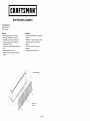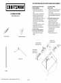
1
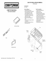
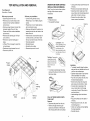
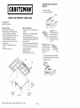
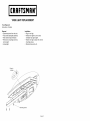
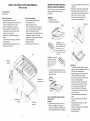
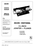
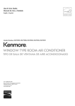
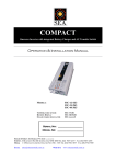
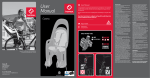
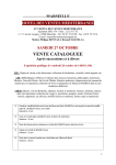
706.596680
6-Drawer
Chest
706.596690
7-Drawer
Roll-A-Way
Craftsman
7-Drawer
AXS
TM
Roll-Away
Section
1612
1613
1614
1615
1616
1617
1618
1623
1624
1625
Owners
Manual
Craftsman
6-Drawer AXS
TM
Description
Chest Top and Facia
Drawer and Work Surface
Bottom Replacement
Top, Wiring Harness, Harness Grommet
Chest Top without Task Light
Task Light Replacement
Locking System
Lock Replacement
Striker Replacement
Drawer Front Replacement
Chest
CHEST
TOP INSTALLATION
AND REMOVAL
(With task light)
i CRAFTSMAN°i
Tools Required:
3/8" Wrench
Chest
CHEST TOP AND FACIA
Top
• Disconnect
PARTS REPLACEMENT
Removal
Chest
power from
unit.
• Remove enough drawers to reach the
top back inside of the unit. (See
actuator
• Push
holding
top in
• Disconnect
• Remove
Chest
wiring
harness
to top.
actuator
rod toward
rod
back of unit
and line up with lock. Insert the
actuator rod into the back of the lock.
place.
• Lift top off of unit enough
wiring harness.
harness
rod is inserted into the actuator
holder in the back of the unit.
rod for access.
(4) screws
Installation
wiring
• Position top on unit.
• Attach using (4) screws.
• Make sure the back of the actuator
Drawer installation
and removal.)
• Push actuator rod to back of unit to
disconnect
from back of lock. Move
• Remove
Top
• Connect
to reach the
• Test lock operation.
• Reinstall drawers.
from unit.
• Reconnect
power to the unit.
top from unit.
Top with light
S
Press to
release
Facia
Disconnect
actuator
Information
Sears,
Roebuck
and Co., Hoffman
Estates,
IL 60179,
Center
USA
F1612
2
rod
INFORMATION
CENTER INSTALLATION
AND REMOVAL
FAClA INSTALLATION
Tools Required:
3/8" Wrench
drill
5/32" drill bit
Rivet gun
Pliers
Tools Required:
Screwdriver, Crosstip
Tape
Removal
Installation
• Disconnect
• Remove
power from
enough
the unit.
drawers
retaining screw under
center. (See removing
• Plug in information
• Position information
to reach the
the information
and installing
• Pull the information
to remove.
center
straight
Note: Tape wire to unit before
unplugging
the information
center.
• Unplug
in unit.
not overtighten.
• Loosen (do not remove) the retaining
screw under the information
center.
will prevent
the unit.
center.
center
• Tighten retaining screw enough to
hold information
center in place. Do
drawers.)
the wire from
the information
retracting
• Reinstall
drawers.
(See Removing
and installing drawers.)
• Reconnect
power to unit.
• Set information
center as desired.
out
(See
AND REMOVAL
information
center
operation.)
This
Rivet
To remove
facia
• Remove
enough
drawers
to reach the
top back inside of the chest.
• Remove lock. (See lock installation
Connector
and removal.)
• Remove chest top. See chest
installation
and removal.
• Carefully drill out (2) rivets
facia to chest.
• Remove
top
holding
facia.
Front
into
To reinstall
• Position
center.
facia
connector
Tape wire in
place before
disconnectin(
Press to
release
facia
on unit. Make sure
is on top of chest.
• Attach using (2) rivets supplied.
• Reinstall lock, chest top, and drawers.
LOCK
INSTALLATION
AND
LOCK INSTALLATION
AND
REMOVAL
To remove lock
• Remove enough drawers to reach the
lock retaining clip behind the lock.
• Remove lock retaining clip. Pull lock
out to remove.
To reinstall
• Position
Lock
Actuator
rod
holder
lock
lock in unit. Install
retaining
'Lock
clip to hold lock in place.
• Make sure the back of the actuator
rod is inserted into the actuator rod
Loosen
holder
retaining screw
• Push
retaining
clip
in the back of the unit.
actuator
rod toward
back of unit
and line up with lock. insert the
actuator rod into the back of the lock.
• Test lock operation.
• Reinstall drawers.
3
REMOVAL
4
CONNECTING
POWER
To reinstall,
• Ensure that the unit and power
are clean and dry.
carefully
push the drawer
drawer stops.
cord
align the slides
and
into the unit until the
Temperature
• insert the round end of the power cord
connector
into the jack in the back of
the unit.
MAX (Maximum
temperature
Jack
INFORMATION
CENTER
OPERATION
The information center is equipped with a
battery backup to maintain memory only.
The display will not function while power
is disconnected from the unit.
Cord
AND
INSTALLING
Outside
optional
DRAWERS:
• Empty the drawer.
• Fully extend the drawer.
Display
temperature
display
outside temperature
Setting
the current
and hour begins
for at least
resets to zero
to flash.)
• Press _
to set am/pm or 24 hour
mode as desired. Note: The am/pm
indicator is not shown in 24 hour
Lever Style - Lift or
lower (depending on the
slide) the release lever
on both sides, (this
allows the slides to ride
temperatures.
• An audible beep will sound when
• Pressing @
• Repeat to adjust
Setting
function
shows
for at least two
O0:O0:O0 and hour
begins to flash.
• Adjust hour using @
is reset.
and @.
toggles to next field.
minute and second.
• Toggling past second exits set mode.
Note: To set timer to 24 hours, toggle
the alarm
display
• Press and hold _
two seconds. (Second
for at least
resets to zero
toggles
minute.
past minute
to 00:00:0O.
• Press _
to start count down.
• Each time _
or stops timer.
• Alarm sounds when
is pressed
timer
hour using (_
reaches
• Press
any button
to silence
the alarm.
exits set mode.
Turning
alarm on or off
When the alarm is activated,
will show the indicator _,.
• Press _
the alarm.
to activate
• Press _
ringing.
to silence
When
the display
in Timer
or Count
mode, press _
time. Press _
count down timer.
or deactivate
alarm
down
timer
to display current
to return to timer or
when
and (_.
• Pressing _
toggles to next field.
Note: To toggle to minute without
changing hour, press _) then (_ then
over the stops.) Pull out
to remove.
Time
•
Tab Style - Depress the
release tabs on both
sides, (this allows the
slides to ride over the
stops.) Pull out to
remove.
• Adjust
minute
using (_
and (_.
Month,
Day, and Year.
\
jTimer
\\
Start/Stop
Clock
Clock Set
Alarm
to
Alarm Set-_
\
\
\
(+)
Temp Inside
Date
(-)
5
Alarm
Activated
AM/PM
D
oF_eoCP_
• Press _
to toggle to next field.
• Repeat to adjust Month, Day, and
Year.
• Toggling past year exits set mode.
• Day of week is displayed according
starts
0O:00:OO.
to next field.
mode.
• Adjust
starts
Clock
time
• Press and hold _
two seconds. (Second
timer
• Display
• Toggling
_
turns the display
on for 15 seconds.
down
• Press and hold _
seconds.
since last reset)
• Pressing _
• Repeat to adjust
backlight
• Pressing
backlight
Release
Count
recorded
• Press and hold _
for at least two
seconds to clear inside and outside
minimum and maximum recorded
temperature
mode.
to start timer.
is pressed
• Press and hold _
for at least
two seconds to reset timer to zero.
and hour begins to flash.)
• Adjust hour using (_ and (_).
requires
sensor.
to enter timer
• Press _
• Each time _
or stops timer.
MIN (Minimum
recorded
temperature
since last reset)
Fuse block
function
• Press _
• Pressing _
toggles inside and
outside temperature
displays between
ACT (Actual temperature)
• Plug the cord into an appropriate
electrical outlet.
REMOVING
Timer
Display
Pressing _
toggles inside and
outside temperature
displays between
Celsius and Fahrenheit.
6
\
Light
Temp outside
(Accessory required)
SLIDE REPLACEMENT
Tools Required:
Drill
5/32" Drill bit
Rivet gun
I CRAFTSMAN°I
DRAWER
AND WORK SURFACE
Removal
• Remove
PARTS REPLACEMENT
Installation
drawer
unit. (See
installation
drawer
or work surface
from
• Separate
slide drawer member from
unit member. (See drawer and work
and work surface
and removal.)
surface
• Carefully drill out rivet holding slide
drawer member to drawer or work
surface.
• Rotate
• Rivet
front of slide drawer
down and out.
• Pull slide forward
• Carefully
member
• install
unit member in place.
• Pull slide unit member
and removal.)
unit member
drawer
in place
member.
(Install
as shown.
(Install
back
hanger first.)
• install rivet to hold slide drawer
to remove.
drill out rivet holding
installation
• install new slide unit member.
back hanger first.)
slide
forward
member
• Reinstall
to
in place.
drawer or work
unit. (See drawer
remove.
installation
surface
into
and work surface
and removal.)
Back hanger
Work
Surface
place
Hanger
pointed up
%,
Drawer
Left side
Slide
Slide
Drawer
Rivet
Sears,
Roebuck
and Co., Hoffman
Estates,
IL 60179,
USA
F1613
2
DRAWER
AND WORK
SURFACE
REPLACEMENT
DRAWER
Tools Required:
Drill
5/32" Drill bit
Tools Required:
Crosstip screwdriver
Rivet
Removal
gun
Crosstip
screwdriver
• Remove
Installation
• Remove
drawer
unit. (See
Drawer
or work surface
and Work
front of slide down
• Pull slide forward
Drawers
• Remove
• Install
surface
installation
and removal.)
• Carefully drill out rivets holding
to drawer.
• Rotate
from
surface.
slides
drawer
(install
rivets
only
• Install
striker.
back
or work
hangers
to hold slides
AND REMOVAL
front assembly
indicated to unhook
• Pull out to remove.
• Position
screw(s).
mounting
as
drawer
front on drawer
assembly.
tabs.
• insert mounting
drawer.
• Slide drawer
first.)
in place.
tabs into notches
front over to attach.
• install retaining screw(s)
drawer front in place.
to hold
(See striker
replacement.)
to remove.
(See striker
• Install drawer front. (See drawer
replacement.)
Drawers and work surface
front.
• Install drawer or work surface
See drawer and work surface
replacement.)
• Remove
on new drawer
• Install
Drawers
and out.
only
striker.
slides
INSTALLATION
Installation
retaining
• Slide drawer
Removal
FRONT
(See drawer
installation
front replacement.)
front
Mounting
tab
in unit.
Notch
and removal.
Retaining
screws
Right side
Siide
Bottom
Hanger
pointed up
Striker
\
drawer only
Drawers (4)inches
deep or more only
Drawer
Left side
Slide
front
o
dJ
,
Rivet
Drawer
3
4
on
DRAWER AND WORK SURFACE
INSTALLATION AND REMOVAL
Note: For pull out work surface without
task light, follow drawer removal
instructions.
• Unplug
work
surface
cord from back of
roll-away.
• Remove and save back retaining clip.
• Disconnect
chain inside back of rollaway. (Move
chain
toward
large round
part of slot. Pull out to remove.)
• Remove the work surface. (See
DRAWER
• Empty the drawer.
• Fully extend the drawer.
drawer
removal
instructions.)
Retaining
clip
Release
Chain
Lever Style - Lift or
lower (depending on the
slide) the release lever
on both sides, (this
allows the slides to ride
over the stops.) Pull out
to remove.
Tab Style - Depress the
release tabs on both
sides, (this allows the
slides to ride over the
stops.) Pull out to
remove.
Installation
• To reinstall, carefully
and push the drawer
the drawer
align the slides
into the unit until
• To reinstall, carefully align the slides
and push the work surface into the unit
until the work surface stops.
• Depress release tabs in back corners
of the extendable
work surface.
stops.
• Push the work surface
into the unit to
the fully retracted position.
• Extend work surface far enough
to
gain access to connections
in back.
• Connect chain inside back of roll
away. (Insert
PULL
OUT WORK
SURFACE
WITH
• Insert retaining
place.
TASK LIGHT
Removal
• Disconnect
chain
the power from the unit.
• Remove enough drawers to gain
access to connections
in the back of
the roll-away
surface.(Follow
instructions.)
behind
the work
drawer
removal
into the large
round part of the slot. Slide chain
small end of slot.)
clip to hold chain
• Plug work surface
roll-away.
• Reconnect
to
in
cord into back of
power to the unit. (See:
Connecting
power.)
• Check work surface
for proper operation.
• Reinstall drawers.
and task lighting
I CRAFTSMAN°I
BOTTOM
REPLACEMENT
Tools Required:
Socket Wrench
5/16" Socket
Removal
Installation
• Disconnect
power from the unit.
• Remove contents from drawers.
• Install counterweight
bottom.
• Carefully
lay the chest
Take care to prevent
damage to the unit.
• Remove
unit.
• Remove
(5) screws
• Remove
bottom.
counterweight
• Position
on its back.
scratches
holding
or
bottom
new chest
• Attach using
screws.
on
• Return
in new plastic
bottom
on chest.
(5) new mounting
the chest
to its upright
position.
bottom
from
unit.
from
• Reconnect
power to the unit,
plastic
Counterweight
F1614
WIRING HARNESS REPLACEMENT
HARNESS GROMMET REPLACEMENT
I CRAFTSMAN°I
TOP, WIRING
HARNESS,
HARNESS
Tools Required:
3/8" Wrench
GROMMET
Parts Replacement
WIRING HARNESS
AND HARNESS
GROMMET
REMOVAL
WIRING HARNESS
AND HARNESS
GROMMET
INSTALLATION
• Disconnect
• Insert
• Remove
power from
pull out work
unit.
surface
and
enough drawers to reach the top back
inside of the unit. (See drawer and
work surface installation
and
bottom
• Install
• Remove lock and top from roll-away.
(See roll-away top removal and
away.
WIRING
• Reinstall
grommet
HARNESS
roll-away,
disconnect
Roll-away
top
• Remove
remove
accent
wiring
in roll-away
from roll-
lighting
harness
through
and
• Reconnect
hole
top.
grommet
Insert assembly
into track in unit.
Sears,
Roebuck
harness
and Co., Hoffman
Estates,
IL 60179,
USA
F1615
lighting,
reconnect
power to the unit.
Grommet
Wiring
over
into hole in top of
top and lock
Harness
Harness
hole in top
• Test lock operation.
• Reinstall drawers.
under
bottom drawer
lighting.
grommet
Insert
• If unit has accent
accent lighting.
REMOVAL
• For units with accent
assembly
of roll-away.
harness
connector.
roll-away.
installation.)
harness
harness
track through
of roll-away (connector
should be on
top.) Slide wiring harness assembly to
removal.)
• Remove
new wiring
into mounting
2
TOP INSTALLATION
DRAWER AND WORK SURFACE
INSTALLATION
AND REMOVAL
AND REMOVAL
Roll-away
top removal
• Disconnect
power from
Roll-away
• Connect
unit.
• Remove pull out work surface. (See
drawer and work surface installation
drawers
Position
screws.
• Remove
(4) screws
holding
wiring
• Push
top in
• Remove
top from
from
chain
toward
large round
removal
instructions.)
the drawer.
Retaining
Release
in the
the back of
Chain
• Test lock operation.
• Reinstall drawers.
to reach the
harness
drawer
the drawer.
• Fully extend
the lock rod toward
• Reinstall
wiring
(4)
• Empty
cord from back of
unit the and line up with lock. Insert
the lock rod into the back of the lock.
harness.
• Disconnect
using
inserted into the lock rod holder
back of the unit.
clip. Pull lock
place.
• Lift top off of unit enough
top on unit. Attach
away. (Move
DRAWER
to top.
surface
part of slot. Pull out to remove.)
• Remove the work surface. (See
• Position lock in unit. Install retaining
clip to hold lock in place.
• Make sure the back of the lock rod is
to reach the
top back inside of the unit. (See
Drawer and Work surface installation
and removal.)
• Remove lock retaining
out to remove.
top installation
wiring harness
work
roll-away.
• Remove and save back retaining clip.
• Disconnect
chain inside back of roll-
Note: For pull out work surface without
task light, follow drawer removal
instructions.
Tools Required:
Screwdriver, Crosstip
and removal.)
• Remove enough
• Unplug
unit.
• Reconnect
Lever Style - Lift or
lower (depending on the
slide) the release lever
on both sides, (this
allows the slides to ride
work surface.
power to the unit.
unit.
over the stops.) Pull out
to remove.
Tab Style - Depress the
release tabs on both
Lock
Press
to
release
sides, (this allows the
slides to ride over the
stops.) Pull out to
remove.
Installation
• To reinstall, carefully
and push the drawer
the drawer
• To reinstall, carefully align the slides
and push the work surface into the unit
align the slides
into the unit until
until the work surface stops.
• Depress release tabs in back corners
of the extendable
work surface.
stops.
• Push the work surface
into the unit to
the fully retracted position.
• Extend work surface far enough
to
gain access to connections
in back.
• Connect chain inside back of roll
retaining
clip
away. (insert
chain
into the large
round part of the slot. Slide chain
small end of slot.)
Lock rod
holder
• insert retaining
place.
Remove
Lock rod
screws
PULL OUT WORK
TASK LIGHT
SURFACE
WITH
• Plug work surface
roll-away.
Removal
• Reconnect
• Disconnect
the power from the unit.
• Remove enough drawers to gain
access to connections
in the back of
the roll-away
3
behind
clip to hold chain
for proper operation.
• Reinstall drawers.
4
in
cord into back of
power to the unit. (See:
Connecting
power.)
• Check work surface
the work surface.
to
and task lighting
DRAWERINSTALLATION
REMOVAL
I CRAFTSMAN°I
• Empty
AND
the drawer.
• Fully extend
the drawer.
Release
CHEST TOP WITHOUT
TASK LIGHT
Tools Required:
Screwdriver, Crosstip
Chest
top
removal
Chest
• Disconnect
power from unit.
• Remove pull out work surface.
drawer
• Remove
installation
enough
(See
and removal.)
drawers
to reach the
• Remove
place.
(4) screws
• Remove
top from
using
• Position
lock in unit. Install
retaining
inserted
(4)
Lever Style - Lift or
lower (depending on the
slide) the release lever
on both sides, (this
allows the slides to ride
into the lock rod holder
in the
over the stops.) Pull out
to remove.
back of the unit.
clip. Pull lock
• Push
holding
installation
top on unit. Attach
clip to hold lock in place.
• Make sure the back of the lock rod is
top back inside of the unit. (See
Drawer installation
and removal.)
• Remove lock retaining
out to remove.
top
• Position
screws.
top in
the lock rod toward
the back of
unit the and line up with lock. Insert
the lock rod into the back of the lock.
unit.
• Test lock operation.
• Reinstall drawers.
• Reconnect
Tab Style - Depress the
release tabs on both
sides, (this allows the
slides to ride over the
stops.) Pull out to
remove.
power to the unit.
• To reinstall, carefully
and push the drawer
the drawer
align the slides
into the unit until
stops.
Lock
Lock
retaining
clip
Lock
holder
Sears,
Roebuck
and Co., Hoffman
Remove
Lock rod
Estates,
IL 60179,
screws
USA
F1616
2
I CRAFTSMAN°I
TASK LIGHT REPLACEMENT
Tools Required:
Screwdriver, Crosstip
Removal
Installation
• Disconnect
power from the unit.
• Fully extend task light assembly.
• Plug in new light.
• Position new light in unit in same
• Make
note of light orientation.
• Remove
remove
• Unplug
(6) mounting
light.
light.
screws
orientation
to
• Fasten
as original
light.
new light in place
with (6) new
mounting screws.
• Reconnect
power to unit.
Press to
Mounting screws
F1617
ACTUATOR
ACTUATOR
I CRAFTSMAN°I
ROD AND ACTUATOR
ROD AND ACTUATOR
CHANNEL
ACTUATOR
REMOVAL
• Disconnect
power from the unit.
• Remove work surface (Roll-away
SYSTEM
pull out work
• Install slot in actuator channel over pin
on lock bar. Move actuator channel
surface
(Roll-
• Insert
away only.) See drawer and work
surface installation
and removal.)
• Remove
enough
drawers
and removal.)
• Push actuator
ACTUATOR
to reach the
disconnect
ACTUATOR
• Insert
CHANNEL
right to remove
flanges.
Channel
Actuator
channel
channel
on inside top of
ROD INSTALLATION
back of actuator
rod into
actuator rod holder in top back of unit.
• Push actuator rod toward back of unit
from back of lock.
• Move actuator
on actuator
flanges
• Insert actuator rod into hole in
actuator channel as shown.
rod to back of unit to
• Rotate actuator rod straight
• Pull out to remove.
top flanges
into mounting
unit.
top back inside of the unit, (See
drawer and work surface installation
Actuator
CHANNEL
fully to the right.
• Remove
Parts Replacement
REPLACEMENT
INSTALLATION.
only).
LOCKING
CHANNEL
down.
and line up with lock. Insert
rod into back of lock.
REMOVAL
actuator
• Test lock operation.
• Reinstall drawers.
fully to the
from mounting
• Reconnect
power to the unit.
Rod Bracket
Remove
through
lock bar
top of unit
Actuator
rod to
actuator
channel
Flexible
front
Move actuator
channel
fully to
right to remove
Actuator
rod
Lockbar
Sears,
Roebuck
and Co., Hoffman
Estates,
IL 60179,
USA
F1618
2
tab
ACTUATOR
ROD
INSTALLATION
BRACKET
AND
LOCK
REMOVAL
Removal
INSTALLATION
power from
• For roll-aways,
unit.
remove
• Disconnect
work
surface.
AND REMOVAL
ROLL-AWAYS, CHESTS WITHOUT TASK LIGHT
enough
drawers
remove
work
surface.
(See drawer and work surface
installation
and removal.
to reach the
top back inside of the unit. (See
Drawer and Work surface installation
and removal.)
• Remove top from
power from the unit.
• For roll-aways,
(See drawer and work surface
installation
and removal.
• Remove
all drawers.
• Remove
actuator
channel.
actuator
unit. (See top
• Remove
rod and actuator
for your unit.
hole in top of
rod bracket
The flexible
Removal
snaps into place. Note:
tab should be in front.
• Reinstall top in unit.
• insert back of actuator
• Slide lock bar down
guide.
• Reinstall
• Reinstall
rod into
actuator rod holder in top back of unit.
• Push actuator rod toward back of unit
and line up with lock. Insert
rod into back of lock.
actuator
actuator
through
lock bar
drawers
to reach the
top on unit. Attach
using
holding
top in
• Position
lock in unit. install
retaining
harness
into the actuator
• Reconnect
lock.
• Test lock operation.
• Reinstall drawers.
from unit.
• Reinstall
top from unit.
and
• Reconnect
work surface.
power to the unit.
rod.
power to the unit.
Lock
to the unit.
Press
to
release
retaining
clip
• JL;
Actuator rod
holder
3
rod
of unit the and line up with lock. Insert
the actuator rod into the back of the
• For roll-aways,
lift top off of unit
enough to access the wiring harness.
wiring
(4)
holder in the back of the unit.
• Push the actuator rod toward the back
clip. Pull lock
place.
• Remove
• Position
screws.
rod is inserted
(4) screws
the wiring
clip to hold lock in place.
• Make sure the back of the actuator
and removal.)
Disconnect
top on unit.
actuator channel
• For roll-aways,
connect
harness to unit.
• Test lock operation.
• Reinstall drawers.
• Test lock operation.
• Reinstall drawers.
power
enough
• Remove
hole in top of
unit.
top back inside of the unit. (See
Drawer and Work surface installation
• Remove lock retaining
out to remove.
Installation
lock bar through
power from
• For roll-aways,
remove work surface.
(See drawer and work surface
installation
and removal.
• Remove
top from unit.
• Lift lock bar out through
unit.
• Insert
unit.
Installation
• Disconnect
(See actuator rod and
channel installation
and
• See top removal
• insert actuator rod bracket into hole in
back corner of unit. Ensure actuator
Tools Required:
Screwdriver, Crosstip
Removal
removal.)
installation
and removal for your unit.)
• Pull actuator
rod bracket forward. Lift
out to remove.
• Reconnect
TOP INSTALLATION
AND
Removal
• Disconnect
• Remove
BAR
REMOVAL
Remove
Actuator
rod
4
screws
CHEST
TOP INSTALLATION
DRAWER AND WORK SURFACE
INSTALLATION
AND REMOVAL
AND REMOVAL
(With task light)
Top
• Disconnect
Removal
Chest
power from
unit.
• Connect
• Remove enough drawers to reach the
top back inside of the unit. (See
actuator
• Push
holding
top in
• Disconnect
• Remove
wiring
top from
harness
to reach the
from
to top.
actuator
rod toward
cord from back of
chain
toward
large round
part of slot. Pull out to remove.)
• Remove the work surface. (See
drawer
the drawer.
• Fully extend
removal
instructions.)
the drawer.
Retaining
Release
rod
back of unit
and line up with lock. Insert the
actuator rod into the back of the lock.
place.
• Lift top off of unit enough
wiring harness.
harness
rod is inserted into the actuator
holder in the back of the unit.
rod for access.
(4) screws
wiring
• Empty
surface
away. (Move
DRAWER
Installation
• Position top on unit.
• Attach using (4) screws.
• Make sure the back of the actuator
Drawer installation
and removal.)
• Push actuator rod to back of unit to
disconnect
from back of lock. Move
• Remove
Top
work
roll-away.
• Remove and save back retaining clip.
• Disconnect
chain inside back of roll-
Note: For pull out work surface without
task light, follow drawer removal
instructions.
Tools Required:
3/8" Wrench
Chest
• Unplug
• Test lock operation.
• Reinstall drawers.
unit.
• Reconnect
Chain
Lever Style - Lift or
lower (depending on the
slide) the release lever
on both sides, (this
allows the slides to ride
power to the unit.
unit.
over the stops.) Pull out
to remove.
Top
Tab Style - Depress the
release tabs on both
Press to
release
sides, (this allows the
slides to ride over the
stops.) Pull out to
remove.
Installation
• To reinstall, carefully
and push the drawer
the drawer
• To reinstall, carefully align the slides
and push the work surface into the unit
align the slides
into the unit until
until the work surface stops.
• Depress release tabs in back corners
of the extendable
work surface.
stops.
• Push the work surface
Disconnect
actuator
into the unit to
the fully retracted position.
• Extend work surface far enough
rod
to
gain access to connections
in back.
• Connect chain inside back of roll
away. (Insert
chain
into the large
round part of the slot. Slide chain
small end of slot.)
Actuator
PULL OUT WORK
TASK LIGHT
rod
holder
Remove
screws
• Insert retaining
place.
WITH
• Reconnect
• Disconnect
the power from the unit.
• Remove enough drawers to gain
access to connections
in the back of
behind
clip to hold chain
• Plug work surface
roll-away.
Removal
the roll-away
5
SURFACE
for proper operation.
• Reinstall drawers.
6
in
cord into back of
power to the unit. (See:
Connecting
power.)
• Check work surface
the work surface.
to
and task lighting
DRAWER AND WORK SURFACE
INSTALLATION
AND REMOVAL
• Unplug
Note: For pull out work surface without
task light, follow drawer removal
instructions.
I CRAFTSMAN°I
LOCK REPLACEMENT
• Disconnect
power from
• For roll-aways,
unit.
remove
work
surface.
(See drawer and work surface
installation
and removal
• Remove
enough
lock retaining
drawers
clip behind
• Remove lock retaining
out to remove.
to reach the
the lock.
clip. Pull lock
Installation
• Position
lock in unit. Install
retaining
clip to hold lock in place.
• Make sure the back of the actuator
rod is inserted
into the actuator
rod
holder in the back of the unit.
• Push actuator rod toward back of unit
and line up with lock. Insert the
actuator rod into the back of the lock.
• Test lock operation.
• Reinstall drawers.
Lock
Actuator
rod
holder
drawer
the drawer.
chain
toward
large round
removal
instructions.)
the drawer.
Rekeying MASTERLOCK ® ONEKEY TM lock
The MASTERLOCK ® ONE_KEyTM
learning lock system allows the
chest and cabinet to be keyed alike.
The lock can also be keyed to most
house keys.
• Insert current key and turn lock to
the right until access notch
appears at top of lock.
• Depress and hold catch through
access notch using re-keying tool
provided.
• Remove key.
• Insert new key.
• Release catch
• Turn lock to center position.
• Remove key
Note: Catch must be depressed to
insert or remove key in right hand
position. Catch may be released
between keys.
cord from back of
part of slot. Pull out to remove.)
• Remove the work surface. (See
• Fully extend
Removal
surface
away. (Move
DRAWER
• Empty
work
roll-away.
• Remove and save back retaining clip.
• Disconnect
chain inside back of roll-
Retaining
Release
Chain
Lever Style - Lift or
lower (depending on the
slide) the release lever
on both sides, (this
allows the slides to ride
over the stops.) Pull out
to remove.
Tab Style - Depress the
release tabs on both
sides, (this allows the
slides to ride over the
stops.) Pull out to
remove.
Installation
• To reinstall, carefully
and push the drawer
the drawer
• To reinstall, carefully align the slides
and push the work surface into the unit
align the slides
into the unit until
until the work surface stops.
• Depress release tabs in back corners
of the extendable
work surface.
stops.
• Push the work surface
Access
into the unit to
the fully retracted position.
• Extend work surface far enough
to
gain access to connections
in back.
• Connect chain inside back of roll
Lock
away. (Insert
retaining
clip
round part of the slot. Slide chain
small end of slot.)
keying
PULL OUT WORK
TASK LIGHT
SURFACE
• Insert retaining
place.
WITH
• Reconnect
• Disconnect
the power from the unit.
• Remove enough drawers to gain
access to connections
in the back of
Sears,
Roebuck
and Co., Hoffman
Estates,
IL 60179,
USA
F1623
behind
for proper operation.
• Reinstall drawers.
2
to
in
cord into back of
power to the unit. (See:
Connecting
power.)
• Check work surface
the work surface.
into the large
clip to hold chain
• Plug work surface
roll-away.
Removal
the roll-away
chain
and task lighting
I CRRFT.TMRN°J
STRIKER
REPLACEMENT
Tools Required:
Screwdriver
Removal
• Remove
drawer
• Turn drawer
• Depress
remove.
from
upside
(2) detents.
Drawer installation
• Emptythe
drawer.
unit.
down.
Push
•
striker
Fully extend
and removal
the drawer.
in to
Release
Depress
detents
Lever Style - Lift or
lower (depending on the
slide) th_ rel_a.£e laver
on both sides, (this
allows the slides to ride
over the stops.) Pull out
to remove.
Tab Style - Depress the
release tabs on both
sides, (this allows the
slides to ride over the
Installation
• Turn drawer right side up.
• Position striker in drawer.
• Push
•
striker toward
until striker snaps
Reinstall drawer.
back of drawer
into place.
stops.) Pull out to
remove.
• To reinstall, carefully
and push the drawer
the drawer
Sears, Roebuck and Co., Hoffman Estates, IL 60179, USA
align the slides
into the unit until
stops.
F1624
I CRAFTSMAN°I
DRAWER
FRONT REPLACEMENT
Tools Required:
Crosstip screwdriver
Removal
Installation
• Remove retaining screw(s).
• Slide drawer front assembly
indicated to unhook
• Pull out to remove.
mounting
• Position
as
drawer
front on drawer
assembly.
tabs.
• Insert mounting tabs into notches
drawer.
• Slide drawer front over to attach.
• Install
drawer
retaining
screw(s)
on
to hold
front in place.
Mounting
tab
Notch
Retaining
screws
Bottom
drawer only
Drawers (4)inches
deep or more only
Sears,
Roebuck
and Co., Hoffman
Estates,
IL 60179,
USA
F1625