1
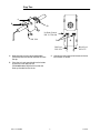
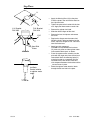
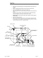
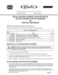
IMI CORNELIUS INC.
One Cornelius Place
Anoka MN 55303–6234
Telephone (800) 238–3600
Facsimile (612) 422–3246
UNIVERSAL 750 ICE BANK CONTROL
KIT P/N 3626
A
B
C
A
C
D
Step One
A. Remove the product lines and white washers.
Clip all poly ties.
C. Remove the agitator motor. Unscrew the hex
nuts and screws holding the plate down. Remove the plate.
B. Unscrew the control box. Disconnect the cord
and agitator motor electrical leads. Lay the
control box over the side of the unit.
D. Disconnect the tubes to the valves. Raise the
basket and remove the ice bank control holder
by bending the top brackets.
8/25/94
1
P/N 185211007
Step Two
A
B
B
Ice Bank Control
P/N 33-5794-000
P/N 3529
C
Red Lead
P/N 3576
A. Snap the new ice bank control bulb holder
(P/N 3529) onto the second and third coil from
the top.
Black Lead
P/N 3575
C. Connect the red and black wire leads to the ice
bank control as shown.
B. Place the ice bank control bulb into the holder
and secure it with two poly ties
(P/N 040056-000). Replace the basket and
hook up the tubes to the valves.
P/N 185211007
2
8/25/94
Step Three
H
S
Apply the Warning Decal (A) to the plate.
Place the plate in the unit with the decal on
the right hand side.
A
S
Tighten the plate to the basket with the hex
nuts. Apply the three screws to each side.
R.H. Bracket
P/N 3531
S
Remove the agitator fan blade.
S
Slide the rubber slinger off the shaft.
S
Remove the heat sink plates and remove
the cover.
S
Replace the slinger onto the motor shaft.
While the shaft is being pushed up into the
motor, adjust the slinger to 1/16I clearance
from the motor base.
S
Apply heat sink compound
(P/N 000113-734) between the brackets
(G), heat sink plates and the agitator motor
and assemble these parts as shown.
S
Place the agitator motor assembly into the
plate with the angle away from the ice bank
control bulb. Mark the mounting holes (H)
using the bracket as a template. Drill the
four holes with a #29 drill bit. Place heat
sink compound between the bracket and the
plate and screw in place.
S
Route the agitator motor electrical leads
through the left rear hole in the plate.
H
L.H. Bracket
P/N 3532
1/16I
G
G
Heat Sink
Plates
Ice Bank
Control relative
to agitator motor
angle.
8/25/94
3
P/N 185211007
Step Four
S
Reconnect all product tubing. Be sure the tapered white nylon washers are
in place.
S
Route the tubing through the back hole of the panel and tie in place.
S
Apply the DANGER decal to the top of the control box.
S
Snap the grommet and the snap bushing into the holes of the control box as
shown.
S
Place the ice bank control in the control box with the capillary tube going
through the grommet. Screw the ice bank control in place.
S
Route the agitator motor electrical leads and the electrical cord through the
snap bushing.
S
Connect all wiring as shown.
S
When connecting ground leads, be sure to attach power cord ground lead
first then apply a nut and tighten. Then apply the ground lead from the agitator motor and then the final nut. Tighten securely
Capillary Tube
Grommet
Agitator Motor Wire
(smooth)
Green Ground wire
Agitator Motor
Red
Jumper Wire
Black
Jumper Wire
Snap Bushing
Agitator Motor
Wire (Ribbed)
Red Wire
Gray Power Cord
P/N 185211007
Green Ground Wire
White Wire
Gray Power Cord Power Cord (Secure
first to Control box
Black Wire
Gray Power Cord
4
8/25/94